Week 2 Challenge : Surface meshing on a Pressure valve
1. Introduction
The main objective of the challenge is to perform a Topology Cleanup and mesh the given geometry of a pressure valve with different mesh length elements to understand the variation in the mesh lengths which is to be forwarded for physics simulations. For this challenge, three different lengths are to be considered.
2. Procedure to Mesh
This section is differentiated into following subsections for the procedures of meshing different components of Pressure Valve.
2.1 Topology Cleanup for Geometry:
Sometimes upon importing a geometry into ANSA there will be cases of missing faces, inconsistent edges or hole formation on the geometry surface. This is set to be cleaned up to perform mesh by using the topology Clean up methods.
These inconsistencies in ANSA can be identified by looking for edges with a red colour indicating a requirement for cleanup.
- After completing the initial Geometry Checks, the intersecting regions are to be looked for from the TOPO deck.
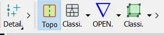
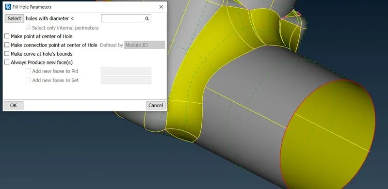
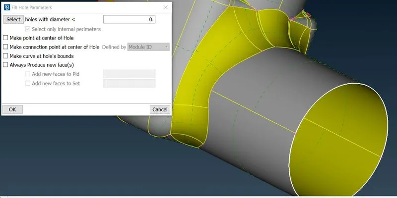
- In the CONS Section of TOPO, FILL HOLE option is selected. This is done to solve the inconsistences on the geometrical surfaces.
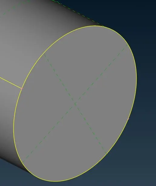
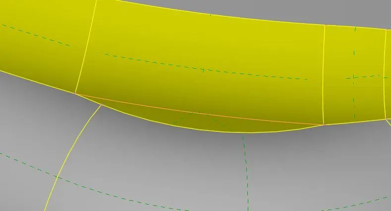
- The edges are to be looked up for inconsistencies as these extra edges or unnecessary edges tends to result in an inconsistent mesh. To solve this issue, CUT option is utilized in the FACE subsection of TOPO deck. which results in eliminating the non-requiring edges. This can be seen represented in the below representation in Orange colour.
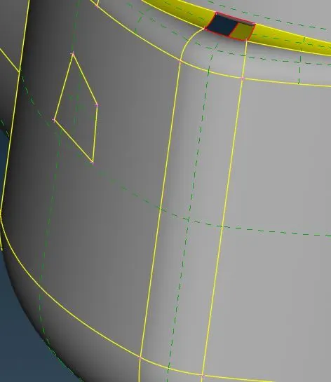
- For a missing face, a new face is to be created at the missing portion for which, EXISTING SURF option is selected in NEW section which prompts towards selection of an identical Face. Base on that, the Face is created.
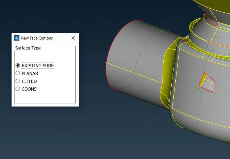
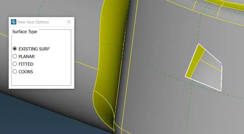
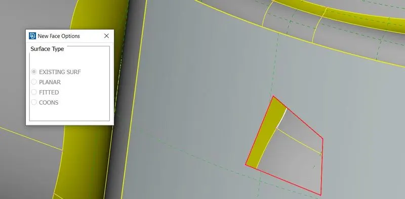
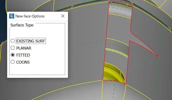
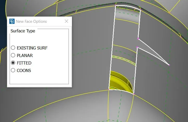
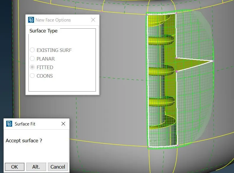
- For the remaining gaps to be filled, a COONS or FITTED option is selected.
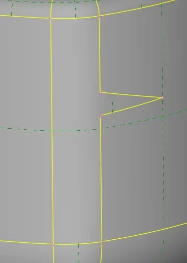
- PIDs are to be assigned at the end of the cleanup procedure to differentiate the Shell and Solid components of the geometry which can be done in the PID section as represented below. This property assignment is indicated in different colors for a better understanding.
2.2 Geometry Meshing:
For meshing up the given geometry, as per the challenge, the mesh has to be done with following mesh lengths of 1 mm, 3 mm and 5 mm respectively for the whole geometry.
2.2.1 Mesh Length of 1 mm:
- To assign the target length of the mesh, it is also necessary to provide the Minimum and Maximum Lengths for the same in-order to get the mesh lengths as close to as possible to the target length. For this, a minimum of 0.5 mm and a maximum of 2 mm have been considered.
- These values are to be specified in both Mesh parameters as well as Quality Criteria as shown below.
- As per the challenge, the mesh element type is to be set to TRIA which can be setup in the Mesh Parameters Section as shown above.
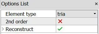
- The Mesh Lengths are to be setup in the LENGTH option which opens a pop-up window with sections of PERIMETER and MACROS. The target Length is to be specified in both the sections as per the representation below.
- Though the entire geometry can be meshed at a go, each individual PID region has been meshed separately in this case in-order to understand the continuity of the Mesh and look for any issues with the generated mesh. It is done using SPOT MESH option in MESH GENEREATION SECTION.
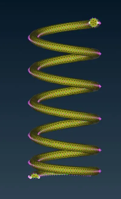
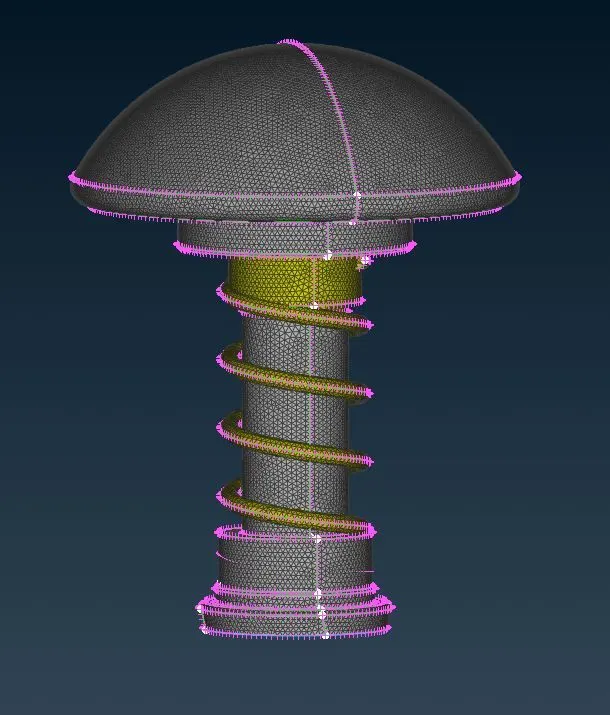
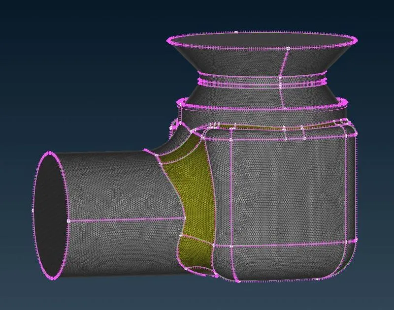
2.2.2 Mesh Length of 3 mm:
- To assign the target length of the mesh, it is also necessary to provide the Minimum and Maximum Lengths for the same in-order to get the mesh lengths as close to as possible to the target length. For this, a minimum of 1 mm and a maximum of 5 mm have been considered.
- These values are to be specified in both Mesh parameters as well as Quality Criteria as shown below.
- As per the challenge, the mesh element type is to be set to TRIA which can be setup in the Mesh Parameters Section as shown above.
- The Mesh Lengths are to be setup in the LENGTH option which opens a pop-up window with sections of PERIMETER and MACROS. The target Length is to be specified in both the sections as per the representation below.
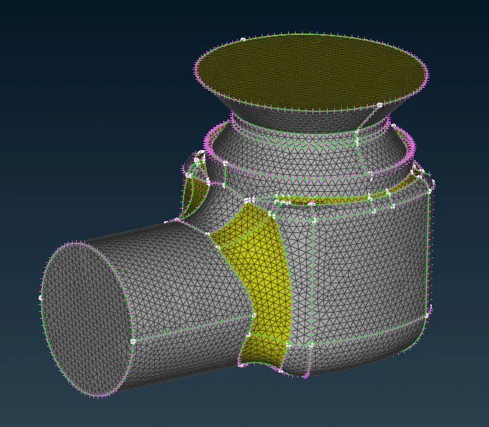
- Though the entire geometry can be meshed at a go, each individual PID region has been meshed separately in this case in-order to understand the continuity of the Mesh and look for any issues with the generated mesh. It is done using SPOT MESH option in MESH GENEREATION SECTION.
2.2.3 Mesh Length of 5 mm:
- To assign the target length of the mesh, it is also necessary to provide the Minimum and Maximum Lengths for the same in-order to get the mesh lengths as close to as possible to the target length. For this, a minimum of 3 mm and a maximum of 7 mm have been considered.
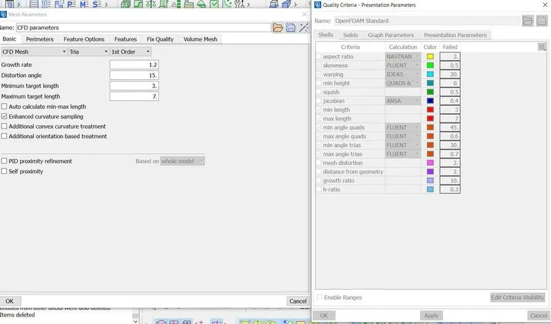
- These values are to be specified in both Mesh parameters as well as Quality Criteria as shown below.
- As per the challenge, the mesh element type is to be set to TRIA which can be setup in the Mesh Parameters Section as shown above.
- The Mesh Lengths are to be setup in the LENGTH option which opens a pop-up window with sections of PERIMETER and MACROS. The target Length is to be specified in both the sections as per the representation below.
- Though the entire geometry can be meshed at a go, each individual PID region has been meshed separately in this case in-order to understand the continuity of the Mesh and look for any issues with the generated mesh. It is done using SPOT MESH option in MESH GENEREATION SECTION.
3. Conclusion
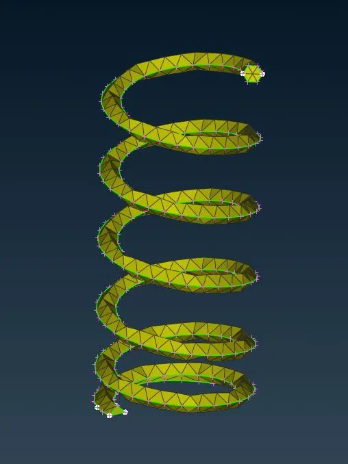
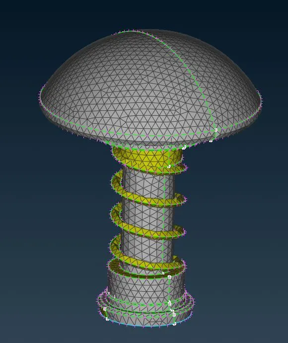
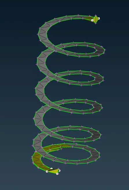
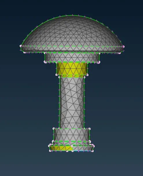
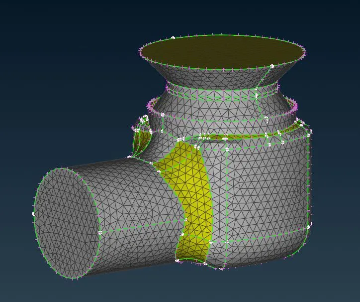
For the components which are smaller than the mesh length, the mesh quality after generation is observed to be too coarse as represented above. But, coming to the case of 1 mm mesh length, the Quality of Mesh is observed to be fine including the smaller components as observed in the section 2.2.1.
Based on the above observations, it has been observed that the Mesh length is directly Proportional to the Mesh Quality. As the Mesh length is observed to be reducing from 5 mm to 1 mm, the Mesh quality for the geometry is observed to be increasing as represented in all the three cases. The requsite ANSA files have been attached and can be accessed from the model link below.
Model Link: Challenge - 2: Surface Meshing on a Pressure Valve (1 mm, 3 mm and 5 mm)