Week 2 Challenge : Surface meshing on a Pressure valve
Aim :
To do geomentry cleanup and generate the surface mesh over the given pressure valve.
Objective:
To identift the single CONS and eliminate them. And generate mesh of tria elements with 1 mm, 3 mm, and 5 mm as the target length.
Introduction :
A pressure relief valve is a type of safty wall used to control and maintain the pressure inside the system. This helps the system to be within the safty limit of operation. The pressure is relieved by allowing the pressurized fluid to flow from an auxiliary passage out of the system. Relief valves are designed to protect compressed air systems from over-pressurisation by releasing excess pressure. Pressure acts against the valve seat and the force generated opens the valve against a spring tension. Should pressure rise above a pre-determined setting, pressure will be relieved through a spring-loaded mechanism which opens due to the increased pressure upstream of the valve, compared to the set point. Once air has been exhausted out of the system, and the pressure has fallen down to its pre-set level, the pressure relief valve will close.
Procedure:
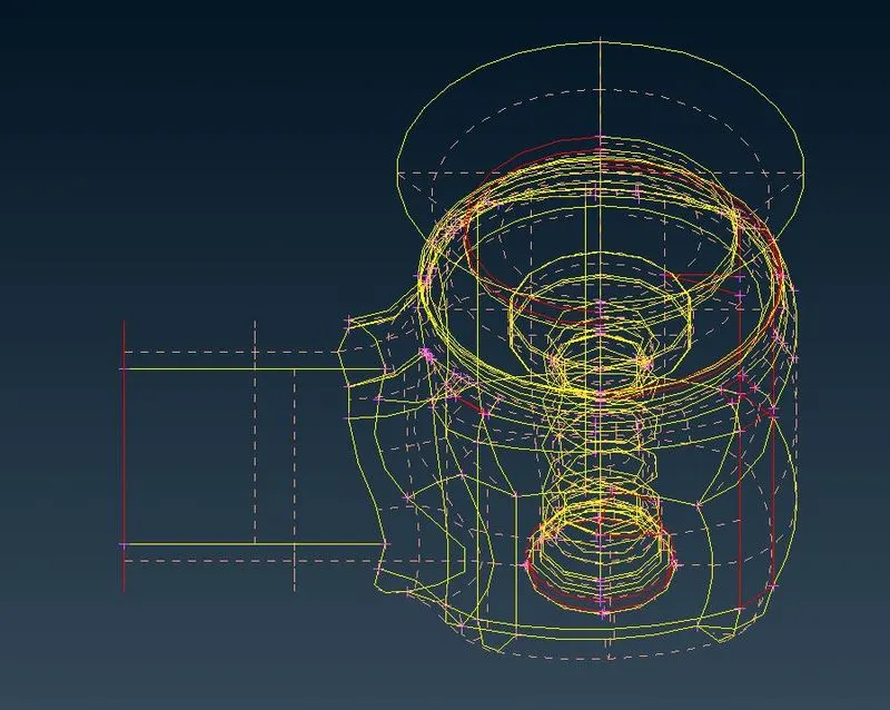
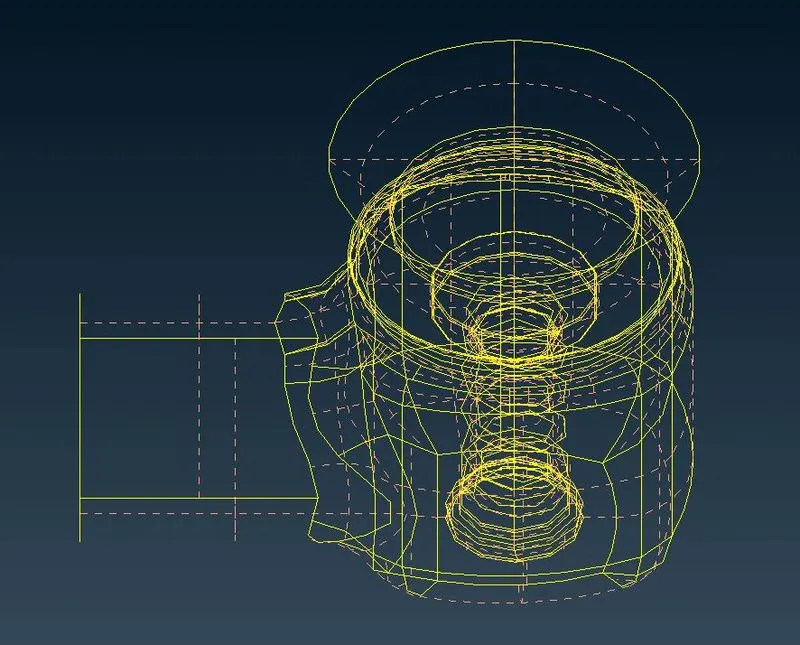
First we import the geomentry to ANSA and the increase the reolution of the geomentry in this case it is specfied as 5 mm. We first visualisation the entire geomentry as a wire frame model to get an idea of exixting single CONS. Then we begin with the geomentry clean up. First we delete the un-necessary hot points in the geomentry,then we use several tools provided by ANSA to convert the single CONS to Double CONS. The can be converted by creating an additional surface or filling the hole options.
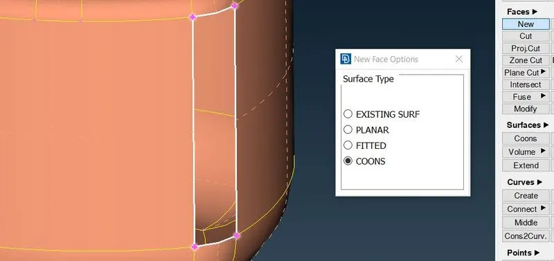
We can use create New face option under FACE, New> Existing Face/Planar/Fitted/CONS > and choose the target space where we need to create new surface.
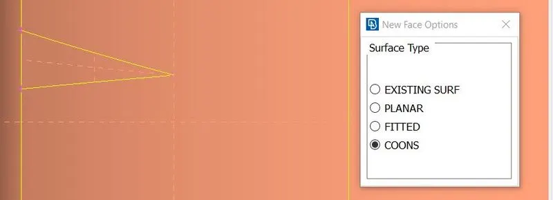
We have to choose the surface type based on the where the single COONS are present , around a curve between / within an existing surface. Because sometimes the created surface is improper with gaps and / or with additional cross hatch like the one below, where it is not advised to have multiple cross hatch over single surface.
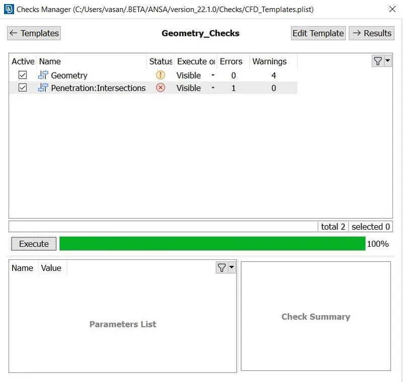
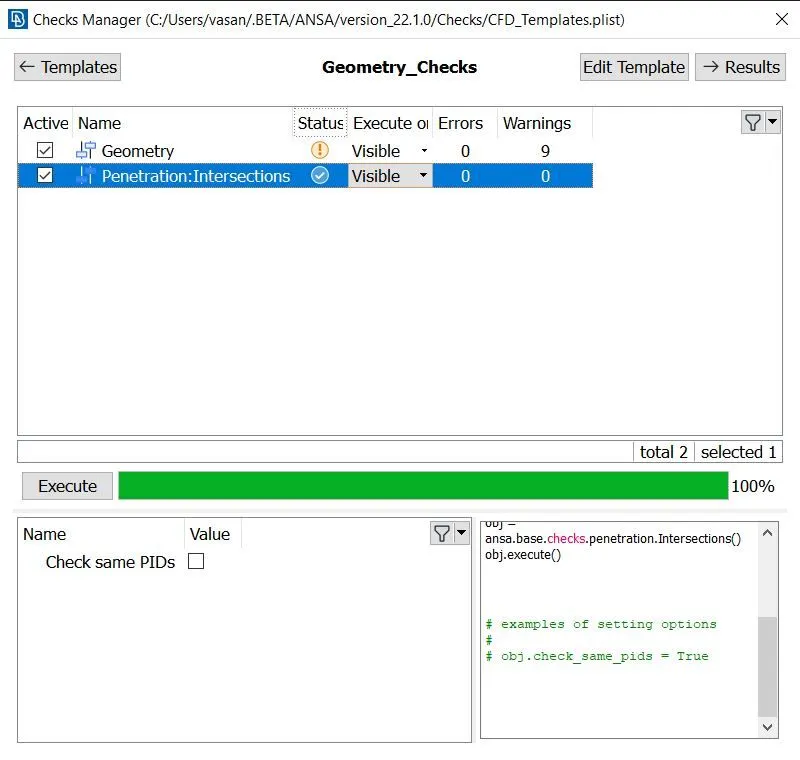
By this way we eliminate all the existing COONS and have only double and triple COONS. Once done we go to checks manager and check for the geomentry errors. And since it is only warnings we can proceed.
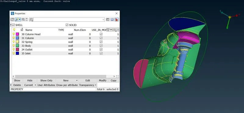
Now we have to define the PID's for each parts in the geomentry for easy identification. For that we open PID console.
New >Shell Property> Apply > Choose the required part using entity option > Name them (Inlet,outlet,spring ,etc..). Therefore each part is assigned different colour for identification. Then we clear the default PID( SHELL_PROPERTY) using Compress option. Once we done for exterior naming we use NOT option to hide exterior parts to define the Parts inside.
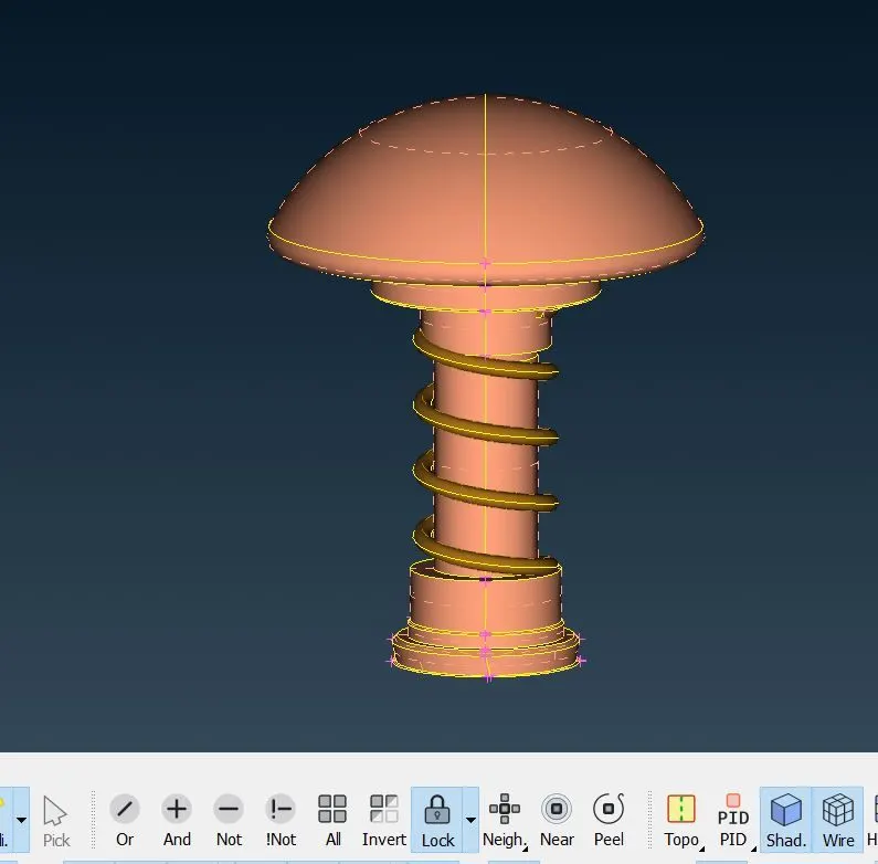
Then we define the parts inside one afer other.
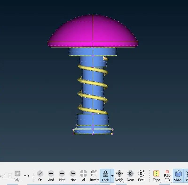
To elimnate the intersection error, which is between column and the spring. We use the Intersection option and choose the two bodies one afer the other and by clicking OK , we get the pop up asking the intersected spring onto the column part to be deleted. Then we again check for the geomentry checks for errors.

Now we have to generete the surface mesh. Since it is for an external simulation we do not need to seperatly create diffrenet mesh for parts inside.
Mesh with 5mm target length
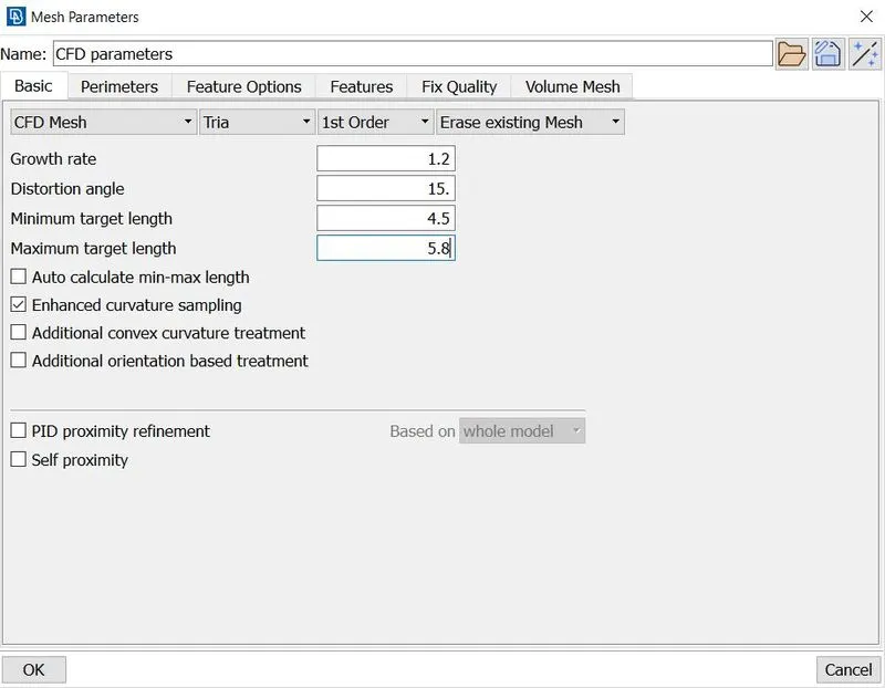
For every mesh we generate the ANSA solver does not create every element with 5 mm as target length so we specify a minimum length and maximum length to for the mesh elements , this gives the solver a range of mesh sizes to be generated within the limit where most of the elements will be within the target length. We select the entire geomentry for meshing, then under spacing in perimeters we choose auto CFD and give the below values as maximum and minimum length , the click on CFD under mesh generation.
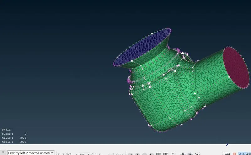
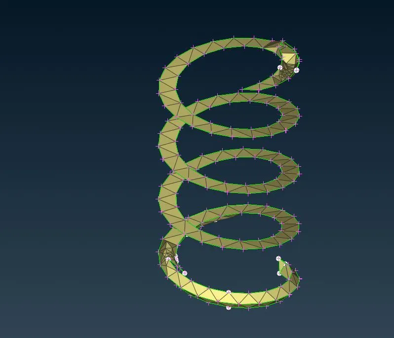
As we can see the mesh outside is course and no structured mesh is present and any surface. Also the spring geomentry is very poorly captured , this will lead to less accurate results.
Mesh with 3mm target length
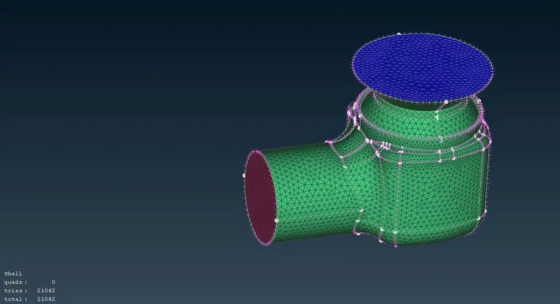
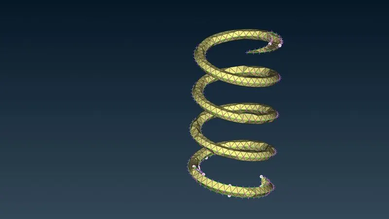
IN this the outer mesh looks decent and it is acceptable, but the spring geomentry is not very well cptured and the edges are still flan and no proper circular profile is caprured. this provides olny better results than the previous case.
Mesh with 1mm target length
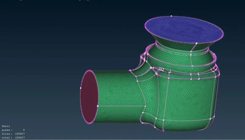
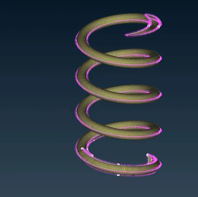
In this target length the mesh generated outside is fine and at some surfaces a structured mesh is visible , which is good. The spring profile is verv well captured and this will result is accurate result out of other previous cases.
Conclusion :
The target length required is based on the geomentry and the type of simulation that we do. The computational time increases with decrease in mesh size and in this case since it is an external simulation and the geomentry is less complex we can have a more refined mesh like 1 mm and will yield very accurate results. But for other geomentry it is not always advisable to have such small mesh size.