Week 2 Challenge : Surface meshing on a Pressure valve
Aim: To perform topology clean up and mesh the geometry with three different mesh length elements.
Take away:
By the end of the discussion one will be able to,
- Get familier with different tools to clean the geometry.
- Use different size mehs elements and figure out which is better for capturing the physics.
CASES:
- Case 1 : Target length as 1 mm.
- Case 2 : Target length as 3 mm.
- Case 3 : Target length as 5 mm.
- By using tria as element type in all the cases.
Procedure:
The procedure for cleaning the geometry for all the cases is same. The only difference is the mesh element size/length.
Initial geometry:
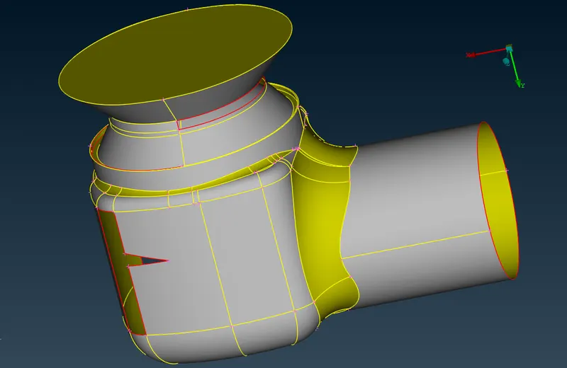
- As seen in the above geometry, there are lot of gaps and unwanted regions which must be taken care of.
- This is done in TOPO deck.
- Mesh deck is the later stage of the process.
TOPOLOGY CLEAN UP:
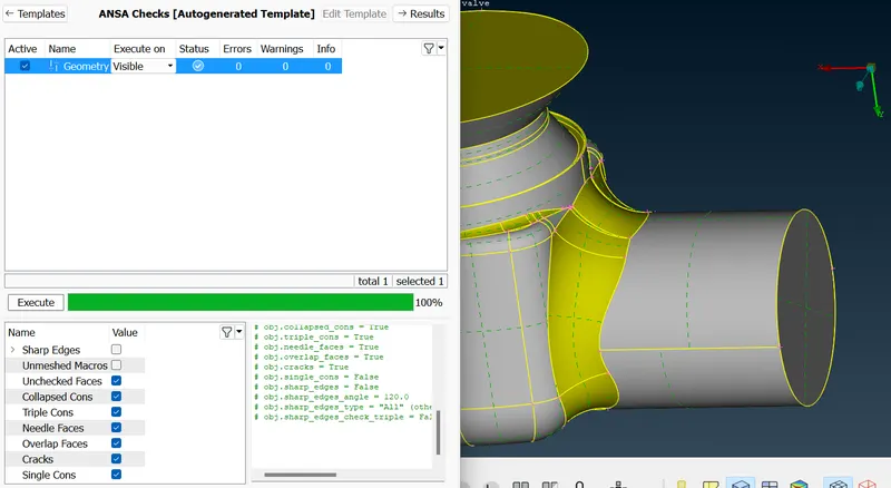
- The very first step is to do a geometry check.
- We get a some of the errors, so that we have to fill the gaps.
- Look out for single and triple CONS or intersecting region.
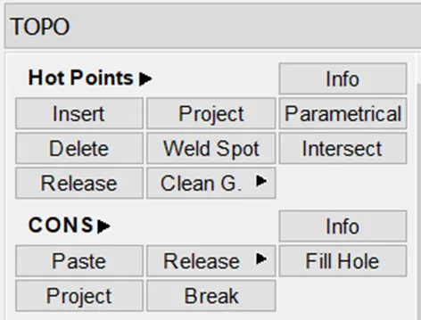
- Exploring the FILL HOLE OPTION:
- Make sure you are in TOPO deck.
- Select FILL HOLE option. (TOPO --> CONS --> FILL HOLE)
- Therefore we have filled all the gaps, by using the insert option.
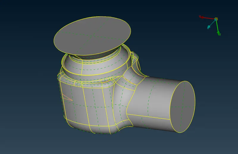
- After filling up all the gaps we get the right status of the geometry. And the warnings, errors and info shows as 0.
Exploring the CUT option:
- Sometimes there could be edges which are unnecessary and might affect the quality of mesh.
- This can be avoided by using the CUT option.
- Selet CUT option. (TOPO --> FACES --> CUT).
- So that the colour of the edges changes to light colour. So that it shows the history of the edges.
- Orange edge makes it redundant.
Exploring the FACES option:
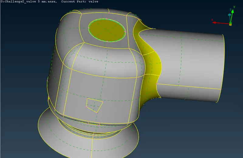
- This option is used when there is a face missing.
- Select FACE option. (TOPO --> FACE --> NEW)
- You will be asked to select any of the four option.
- When any one of the option does not work, try using other option out of the four.
- Like wise any unfilled area can be filled with using this option.
We have to close the base as well to mes the model. So we get the triple cons in the base of the model. But we are ignoring that.
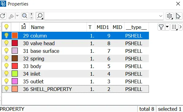
Assigning the respective PIDs:
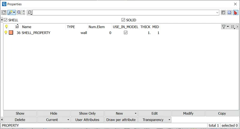
- Select PIDs option present at the top left corner of the viewport.
- A window will pop up.
- In properties we have to give the name of the model.
- Right clicking on the window will pop up. Selec New --> Shell Property
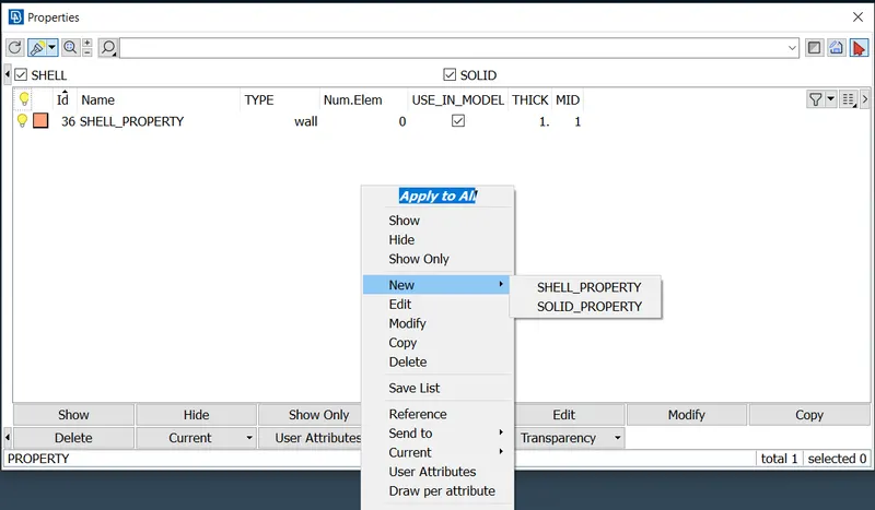
- We have to give all the name selections of the given model as inlet, outlet, body, spring, base surface, volume head and column. Names can given as our requirement.
MESHING THE GEOMETRY:
Topo and meshing procedure is same for all the cases. But we have to change the values accordingly.
- There are three cases as defined above. (1mm, 3mm, 5mm).
CASE 1:
- Target Length = 1 mm
- Minimum Length = 0.5 mm
- Maximum Length = 2 mm
- These values must be specified in ANSA in MESH PARAMETERS AND QUALITY CRITERIA.
- Make sure element type is TRIA.
- Select SPOT MESH option under MESH GENERATION TAB.
- Select LENGTH option from PERIMETERS tab. (MESH --> PERIMETERS --> LENGTH)
- Select perimeters, drag all over the geometry to select the whole geometry and assign the value of mesh length as 1 mm. Similarly do it for macros.
- Select one by one component or do the box selection.
- Then generate the mesh.
Results :
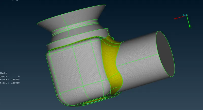
Body, inlet, outlet and base surface :
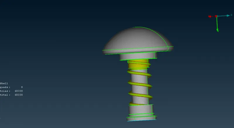
Valve head and column :
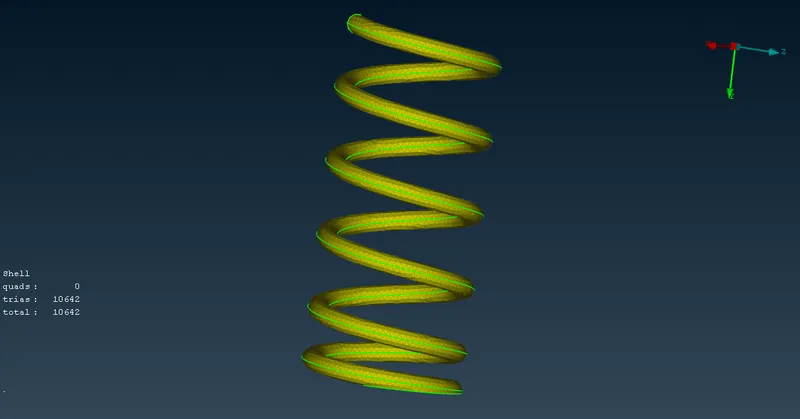
Spring :
CASE 2:
- Target Length = 3 mm
- Minimum Length = 2 mm
- Maximum Length = 5 mm
- These values must be specified in ANSA in MESH PARAMETERS AND QUALITY CRITERIA.
- Make sure element type is TRIA.
- Select SPOT MESH option under MESH GENERATION TAB.
- Select LENGTH option from PERIMETERS tab. (MESH --> PERIMETERS --> LENGTH)
- Select perimeters, drag all over the geometry to select the whole geometry and assign the value of mesh length as 1 mm. Similarly do it for macros.
- Select one by one component or do the box selection.
- Then generate the mesh.
Results :
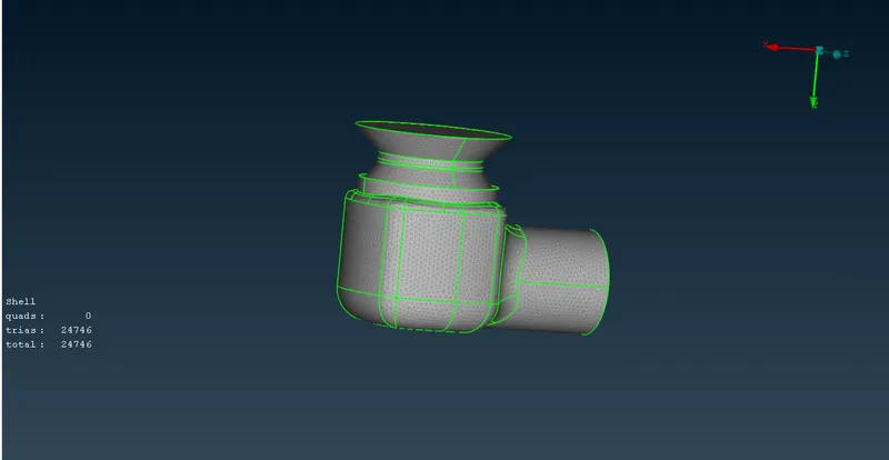
Body, inlet, outlet and base surface :
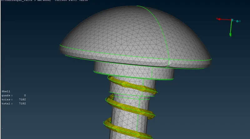
Valve head and column :
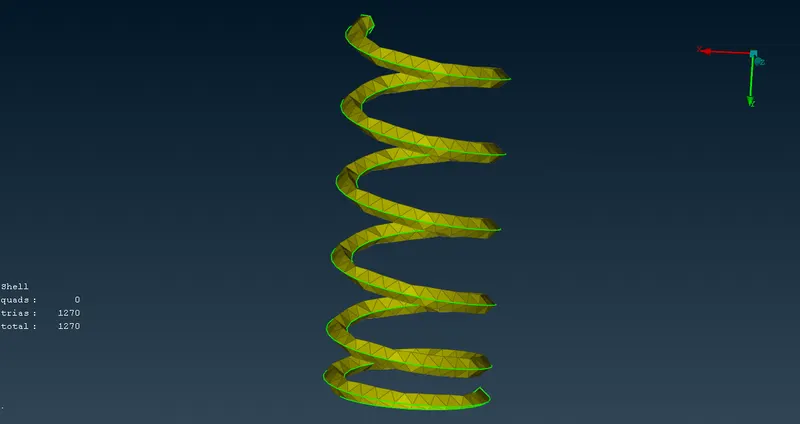
Spring :
CASE 3:
- Target Length = 5 mm
- Minimum Length = 3 mm
- Maximum Length = 7 mm
- These values must be specified in ANSA in MESH PARAMETERS AND QUALITY CRITERIA.
- Make sure element type is TRIA.
- Select SPOT MESH option under MESH GENERATION TAB.
- Select LENGTH option from PERIMETERS tab. (MESH --> PERIMETERS --> LENGTH)
- Select perimeters, drag all over the geometry to select the whole geometry and assign the value of mesh length as 1 mm. Similarly do it for macros.
- Select one by one component or do the box selection.
- Then generate the mesh.
Results :
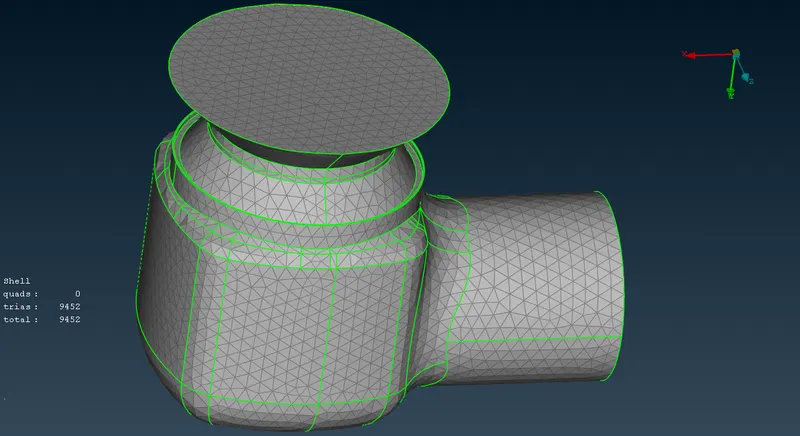
Body, inlet, outlet and base surface :
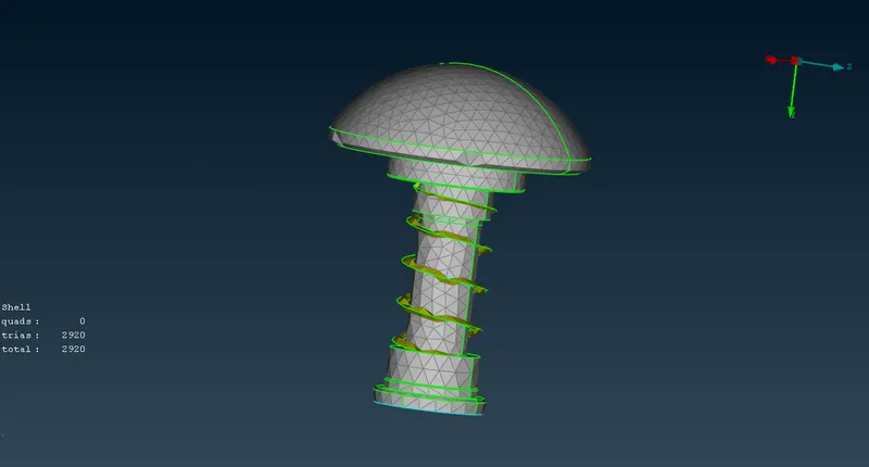
Valve head and column :
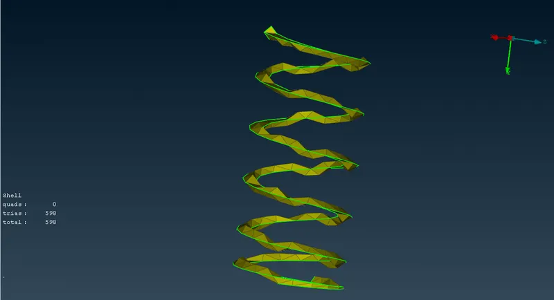
Spring :
Conclusion:
- Mesh length of 1 mm gives very fine results compared to other two cases.
- In cases 2 and 3, the mesh element size is greater than the smallest feature of the geometry. Hence it is unable to capture those areas approriately.
- If seen in the last case, the spring is pretty much flatend, which is not the desirable result.
- Similary in case 2, the valve head is not mesh properly. It has distortions near the circumference.
- Therefore, this concludes that, case 1 is the best mesh out of the three and must be used for furtur analysis.