Week 2 Challenge : Surface meshing on a Pressure valve
AIM
To compare the meshing based on the different mesh size on a pressure valve.
OBJECTIVE
For the given model, check for the geometrical errors and perform Topology clean-up accordingly. Set three different target lengths as three different cases and mesh the model.
- Target length = 1mm, 3 mm and 5 mm (i.e., 3 cases)
- Element type = Tria
Apply any one target length from the above at a time for the entire model as One case. Submit 3 different models for 3 cases.
Write a detailed report on your meshing process and also mention which case is giving good results along with the reason.
Process of any simulation:
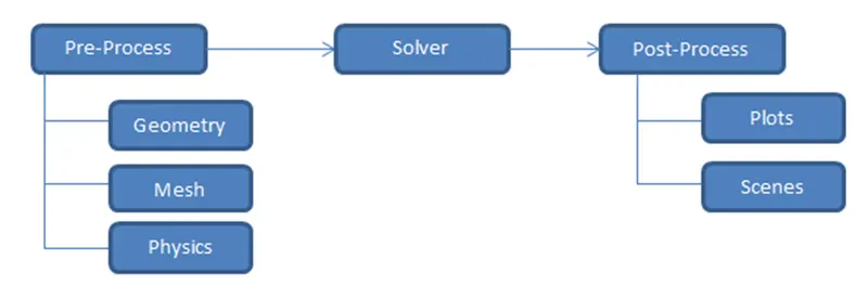
In this challenge we will be doing the pre-processing (Geometry and mesh only)of the given model in ANSA software.
PROCEDURE:
- IMPORTING THE MODEL TO ANSA
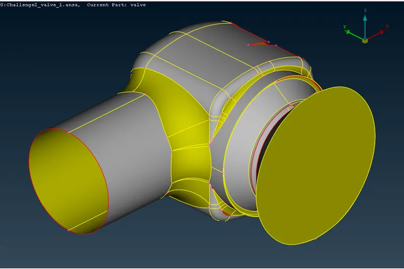
- TO CHECK THE ERRORS IN THE MODEL
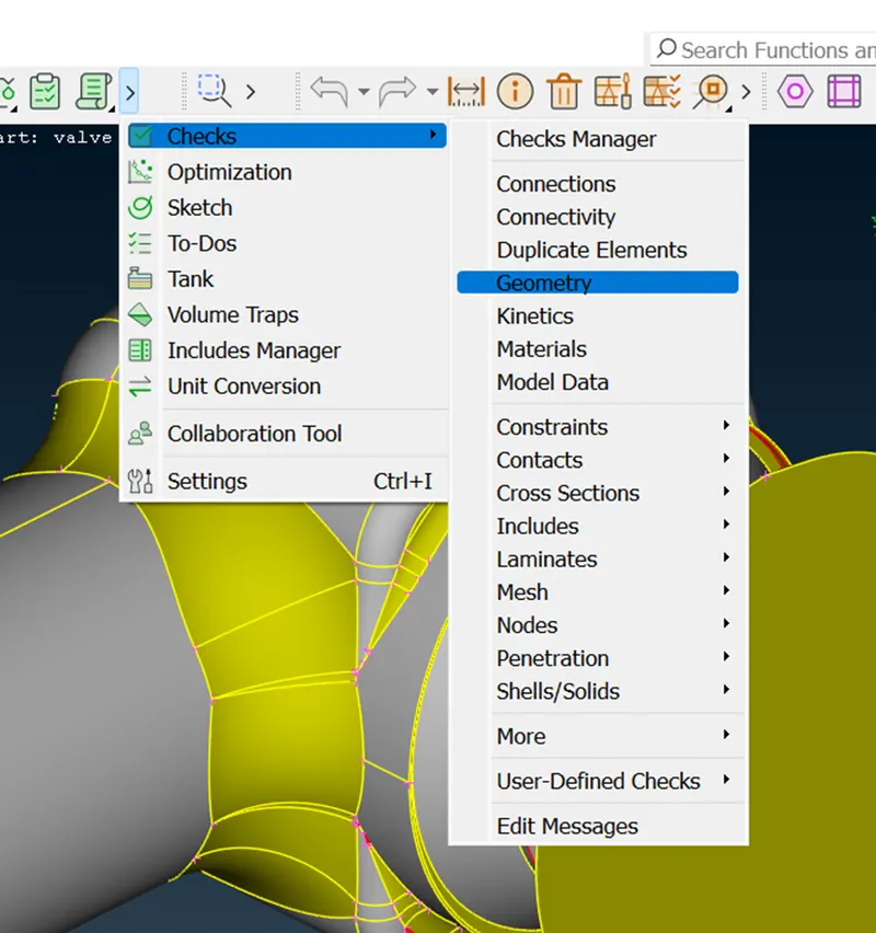
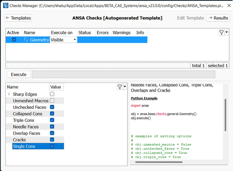
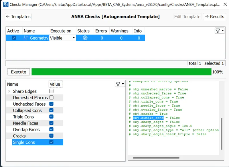
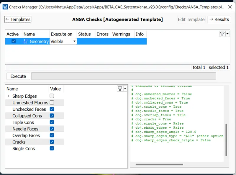
In ANSA, we can find out the errors present in geometry.This is done by using Checks command.In Checks command Geometry is selected.
We have to eliminate Single CONS.
We have to enable Single CONS.
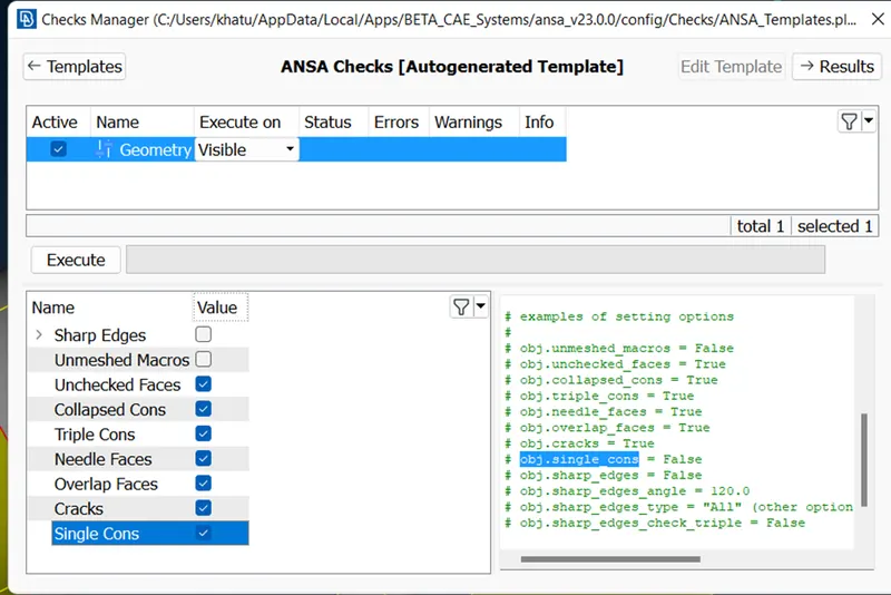
Execute the Checks
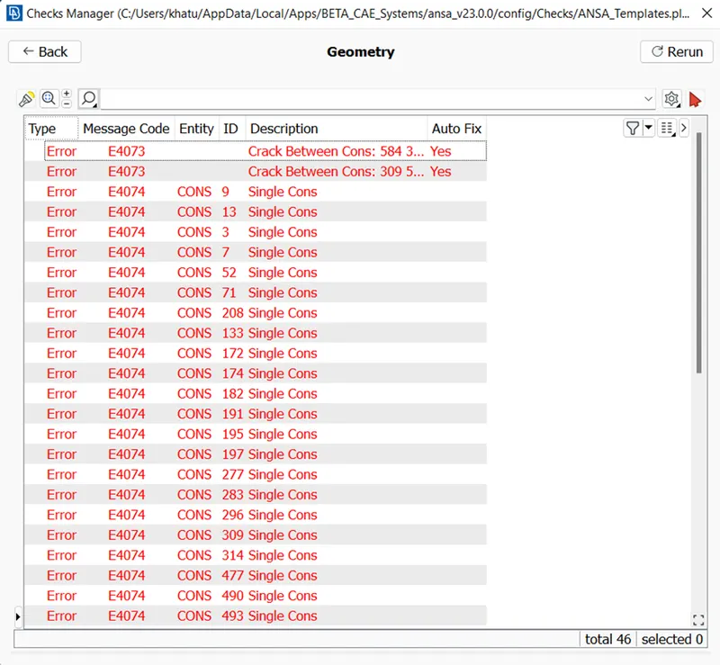
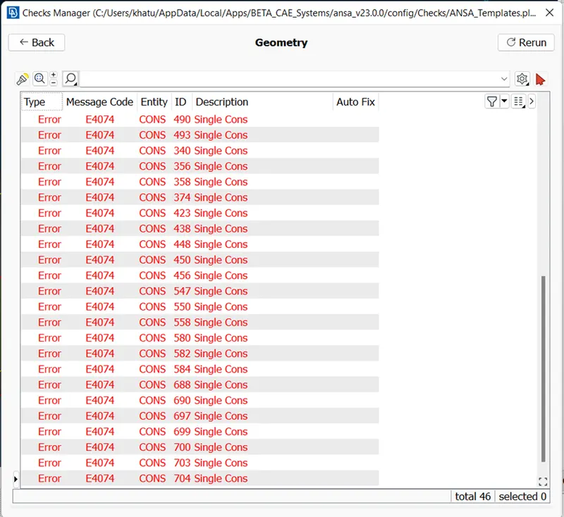
----------------------------------------------------------------
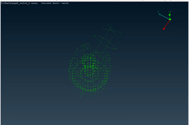
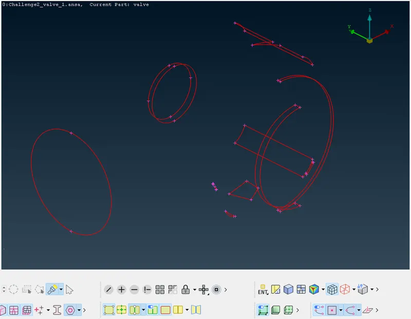 Single Cons in wire frame mode
- TO RECTIFY THE ERROS(TOPOLOGICAL CLEAN-UP)
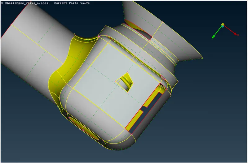
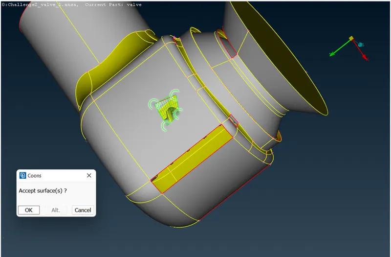
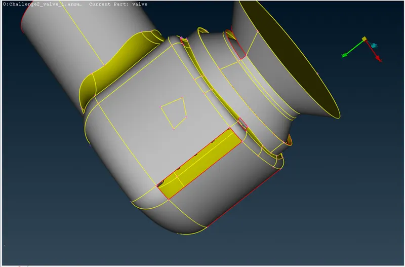
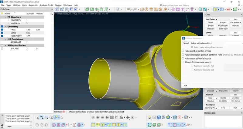
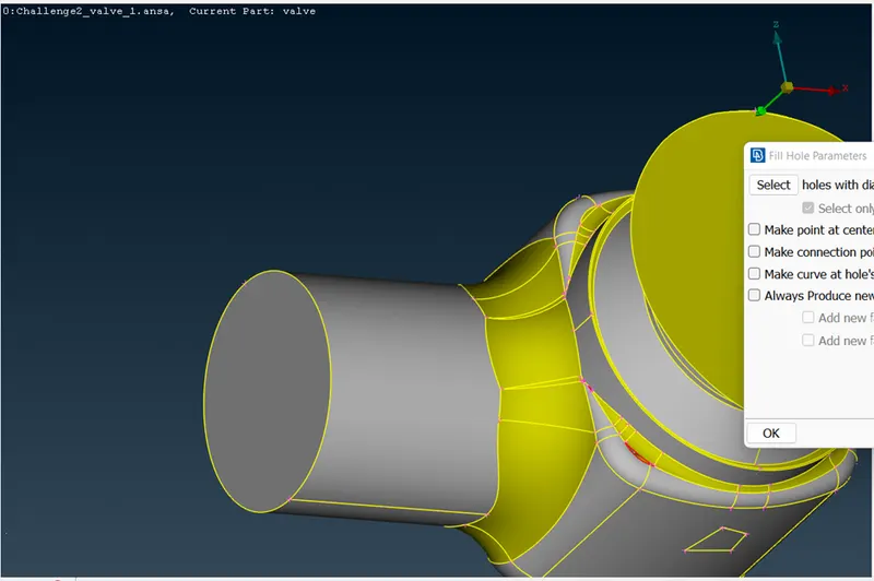
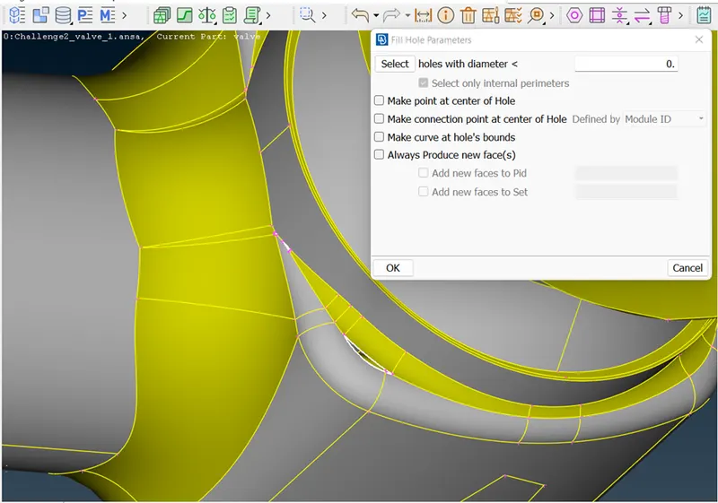
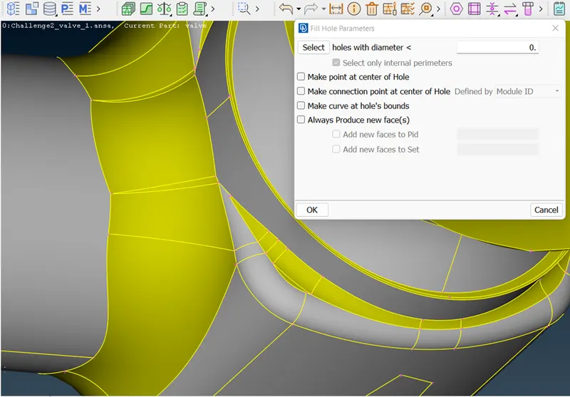
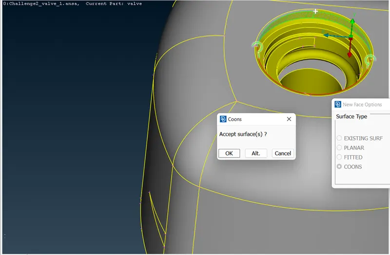
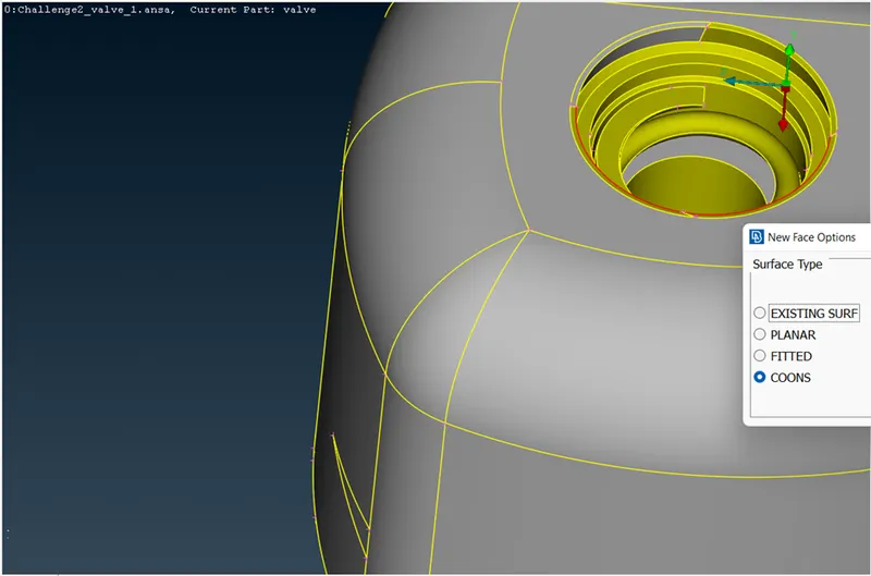
Topological clean-up is done by using NEW command in FACES.this creates new faces by using the existing CONS .Topological clean-up can also be done by using FILL HOLE command in CONS.
- EXISTING SURF
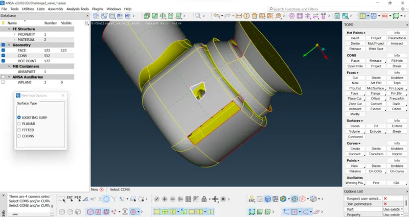
- FILL HOLE
- COONS
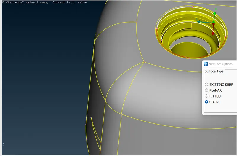
Wire frame model with only Single CONS enabled
- TO CHECK ERRORS IN GEOMETRY AFTER PERFORMING TOPOLOGICAL CLEAN-UP
As seen in below there are now Single CONS present in the geometry now.
As we are performing simulation for CFD ,it needs to be a closed geometry. But there is still a face remaining to be created.
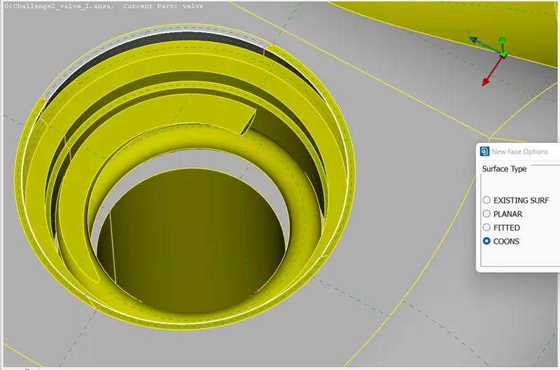
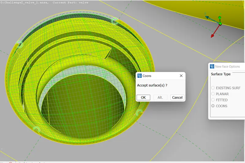
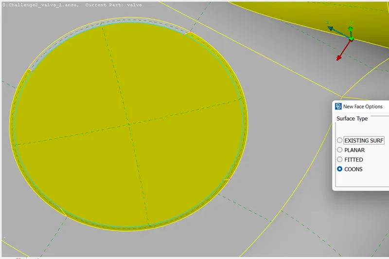
As it is seen it the above figure that a Triple CON is being created .
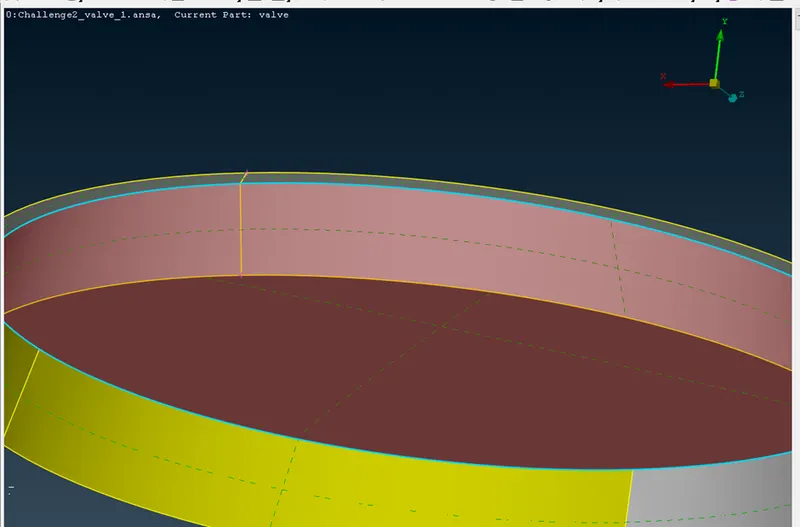
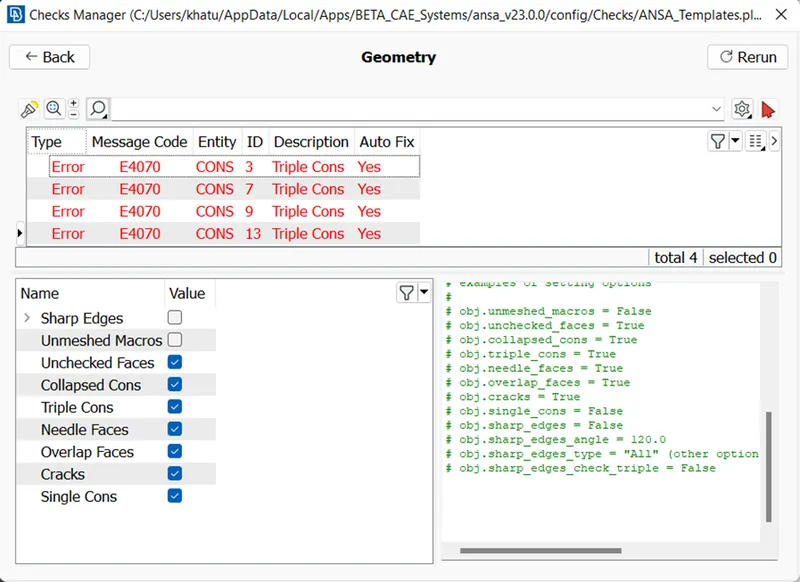
Though in the CHECK geometry ,Triple CONS are shown as errors .In practice they are not errors but warning signal.
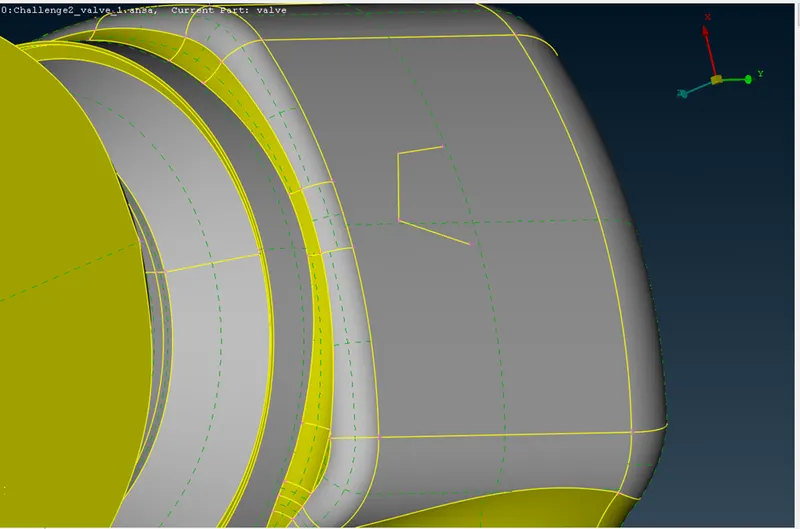
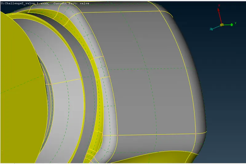
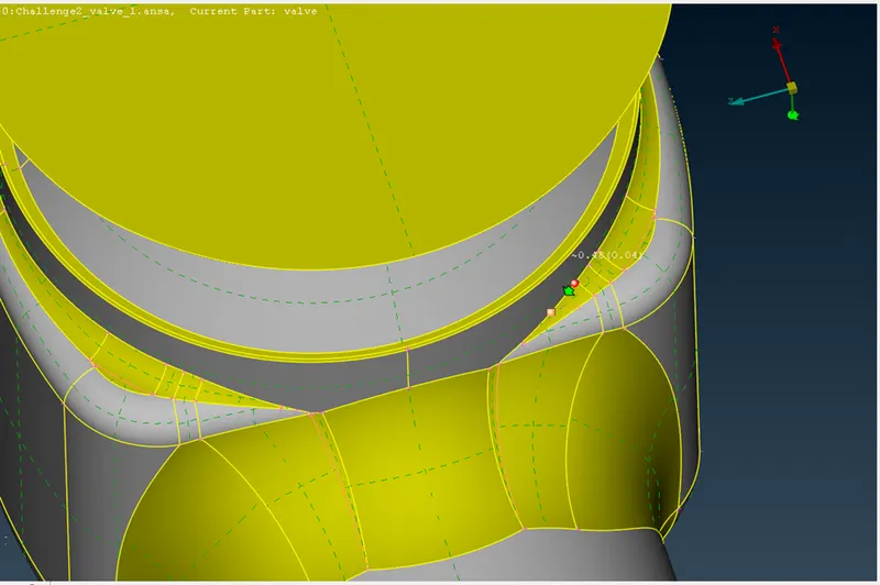
- TO ELIMINATE SMALLER SURFACES(COONS HAVING DISTANCE LESS THAN MESH SIZE)
This is done by using CUT command in Faces.
- TO ASSIGN THE BOUNDARY CONDITIONS
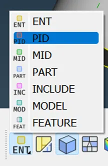
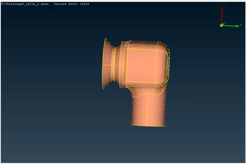
- Enable the PID view
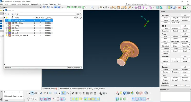
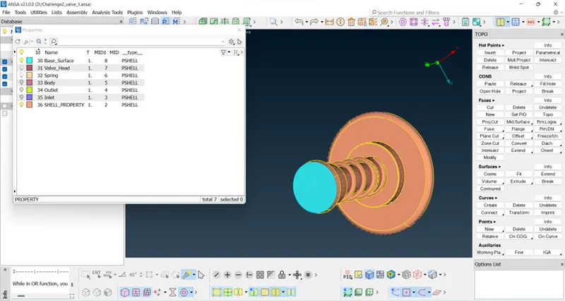
- Add properties (to assign boundary conditions)
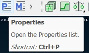
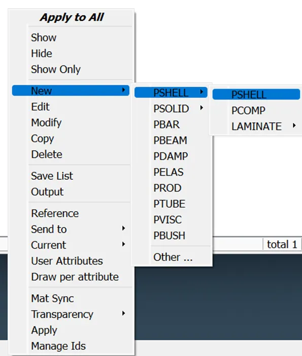
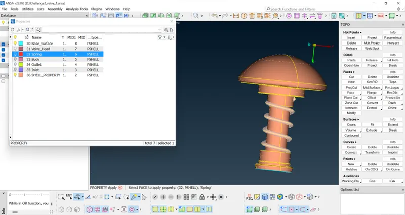
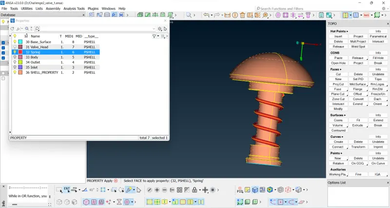
Properties like inlet, outlet, body(outer casing), spring, valve head, column
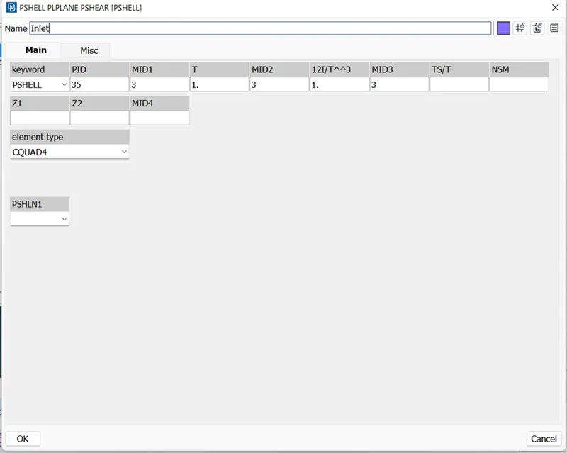
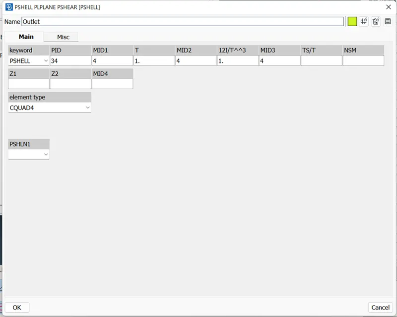
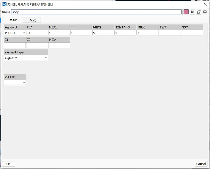
Now to do name selection,we can use ENT/PID/PID Region depending upon the type of selection
- inlet
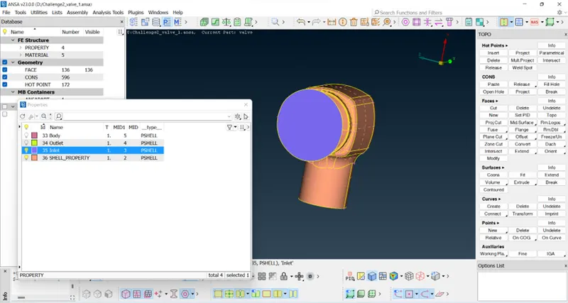
- outlet
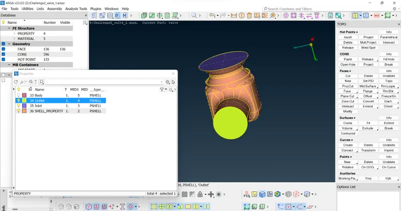
- body
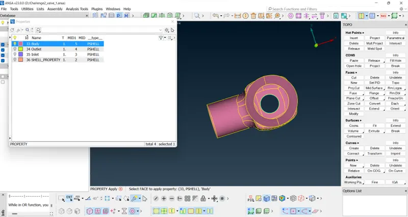
we first need to isolate the outer casing from the inner components and then hide inner components and select the outer casing for body
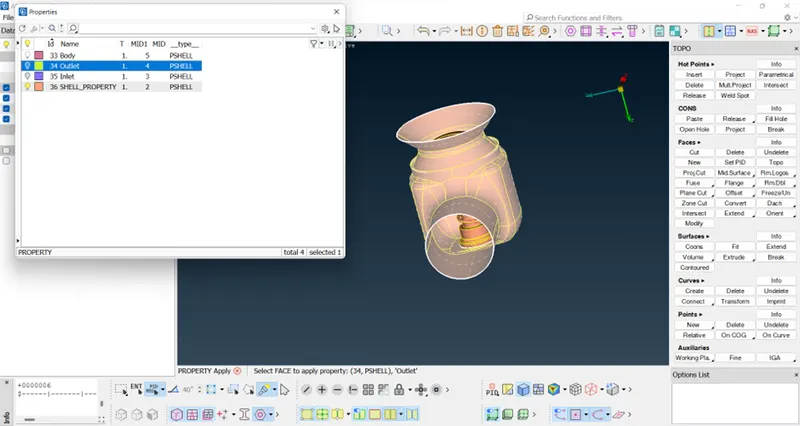
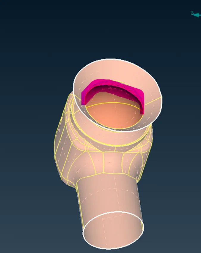
Since there is a gap present in the two surfaces(pink highlighted portion),the inner part is not getting selected.
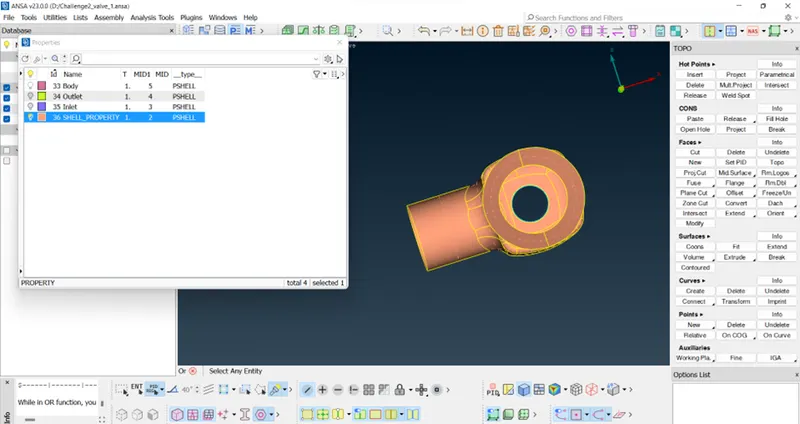
Use OR option to isolate the outer casing
now the unhide inner components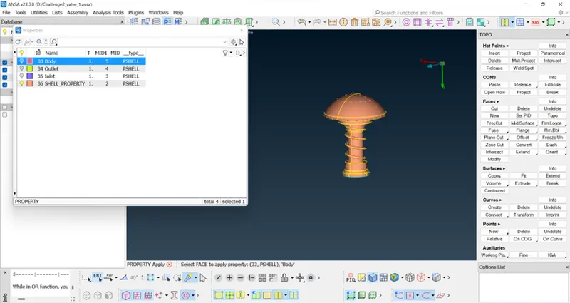
- base surface
- spring
- valve head
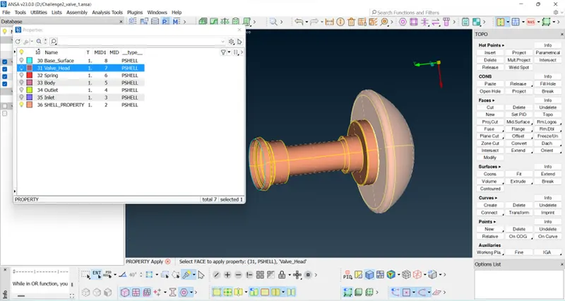
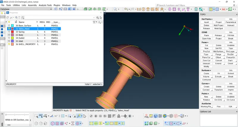
- column
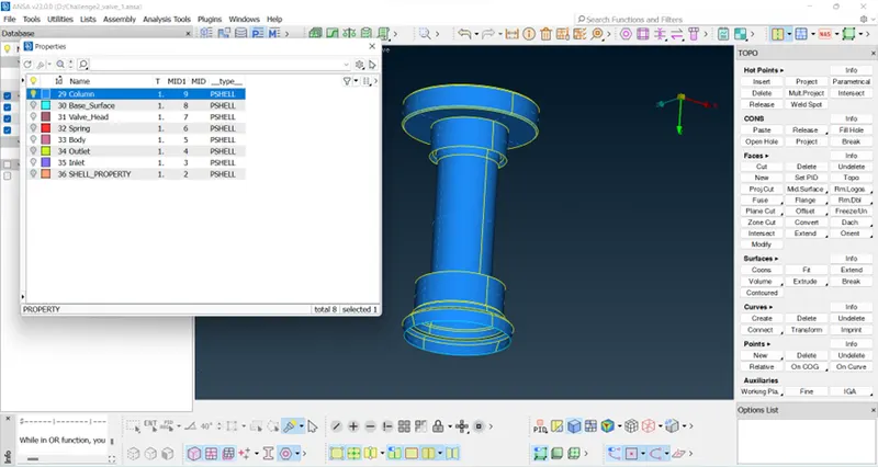
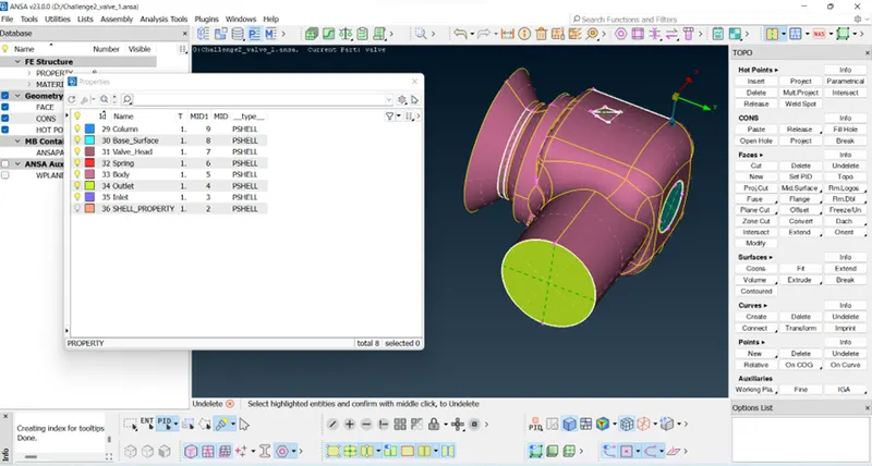
Overlapped surfaces
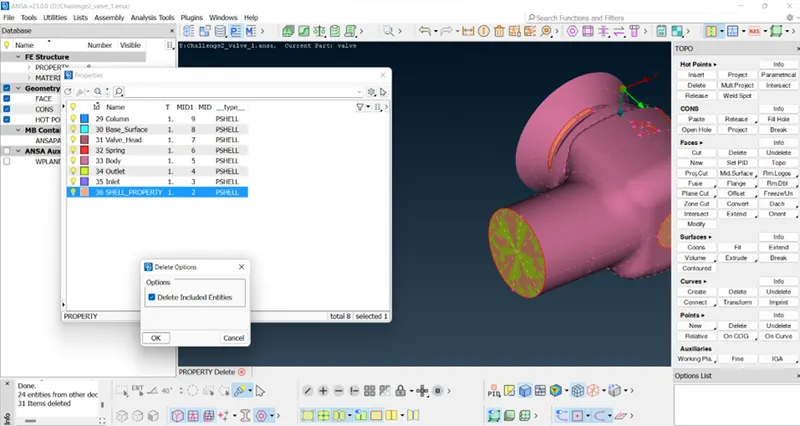
We need to delete SHELL_PROPERTY from the propperties tab.But it will not delete as we have used SHELL_PROPERTY as reference to delete other faces.It also indicates that some of faces have overlapped during name selection.we need to find Overlapped surfaces and then delete them (SHELL_PROPERTY)
- FINDING OUT OVERLAPPED SURFACES
This is done by using UNDELETE command in the FACES.
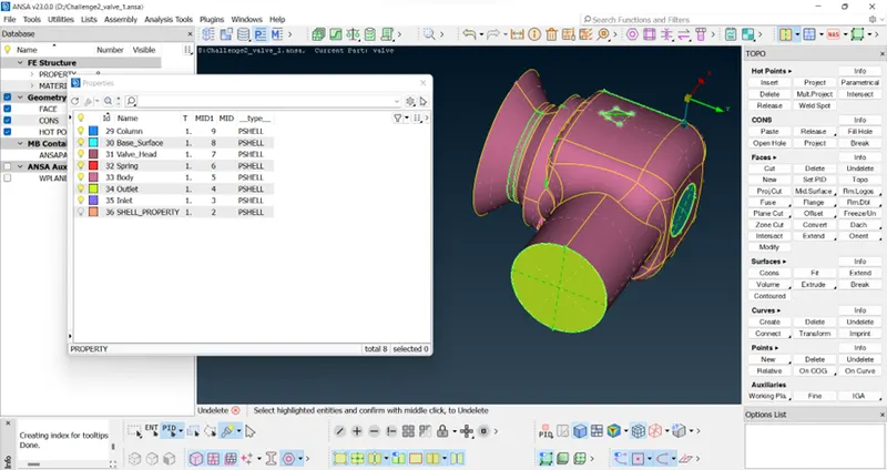
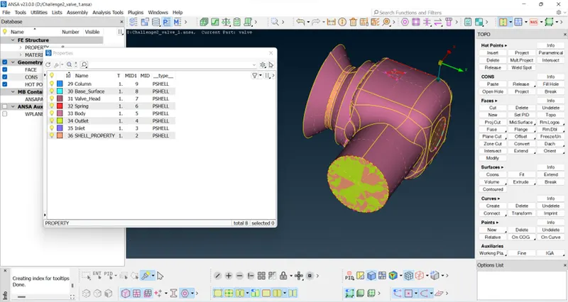
- DELETING THE OVERLAPPED SURFACES
- START MESHING
We have to create a mesh having
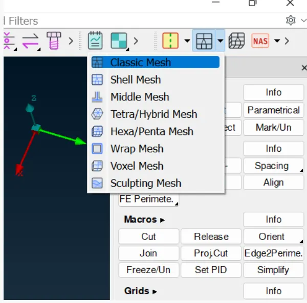
- for this select Classic Mesh in Mesh Module.
- now select Length in Perimeters
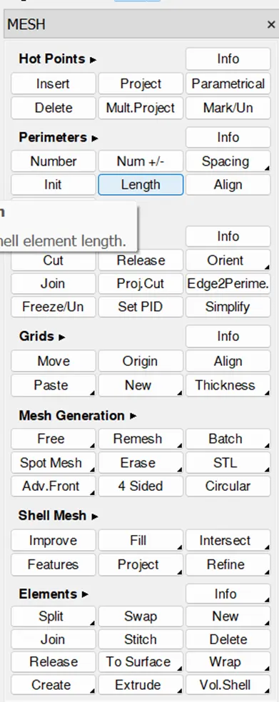
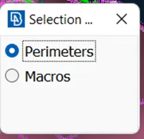
- prop window will appear having Perimeters and Macros
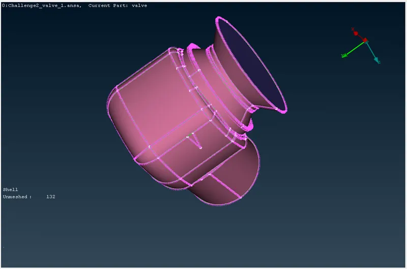
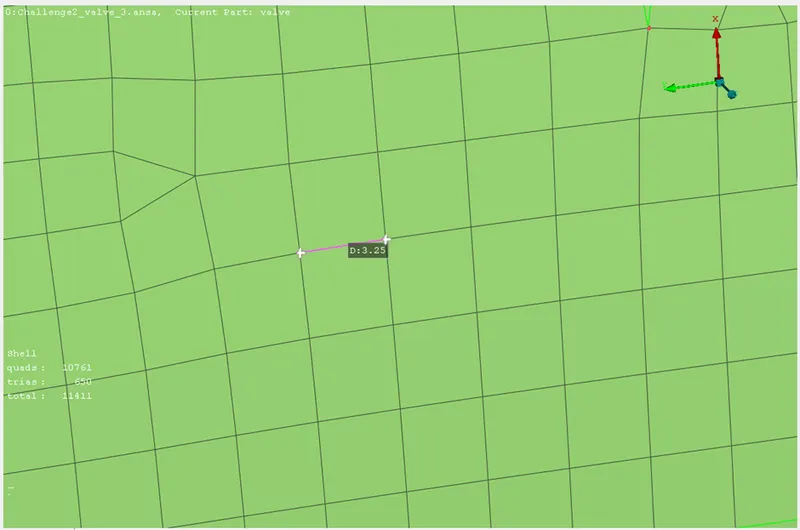
- for the options we have to box select the geometry and give length as 3 mm
- Perimeters-green portion
- Macros-enclosed in perimeter
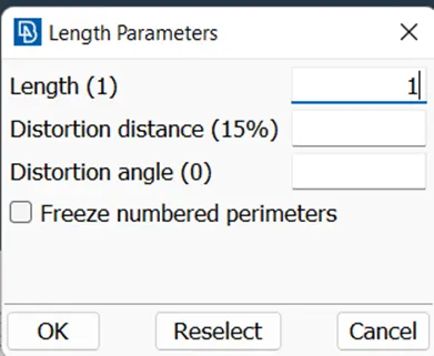
In the mesh parameters,giving target length as 1/3/5 and minimun length.
| target length | minimum length | maximum length |
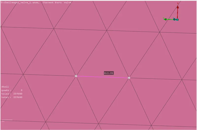
| 1 mm | 0.5 | 2 |
| 3 mm | 1 | 5 |
| 5 mm | 3 | 7 |
in the quality criteria, we have to minimum length and maximum length according to target length as given in the above table.
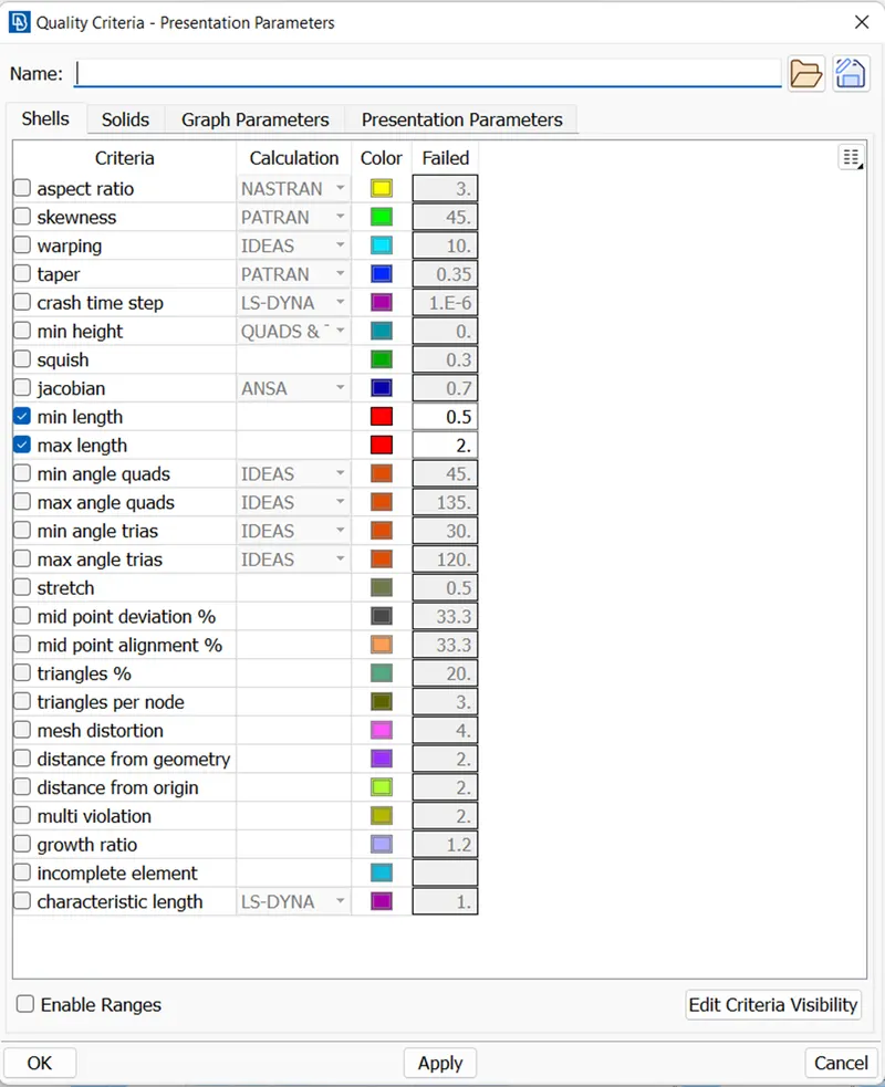
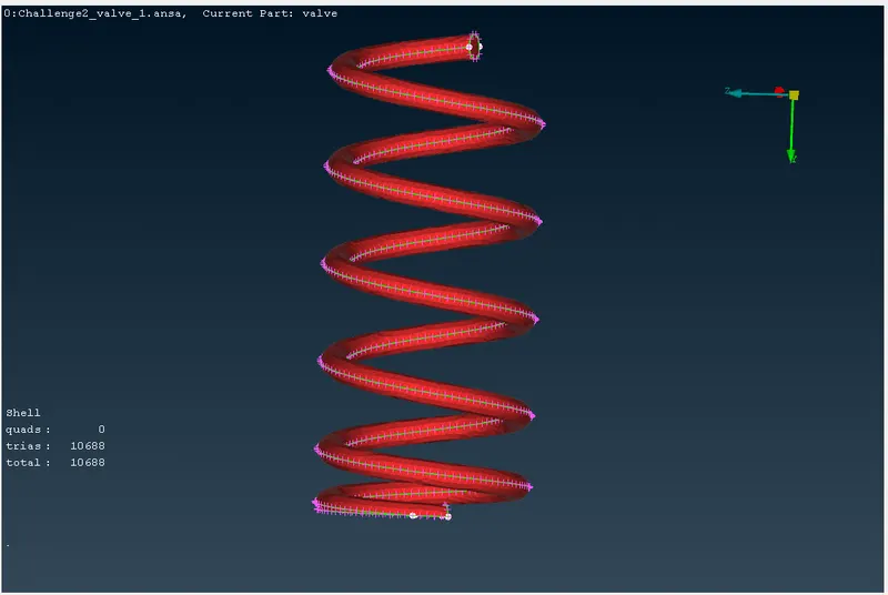
FOR 1mm
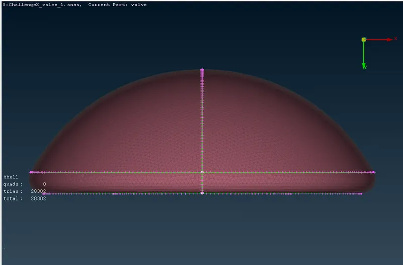
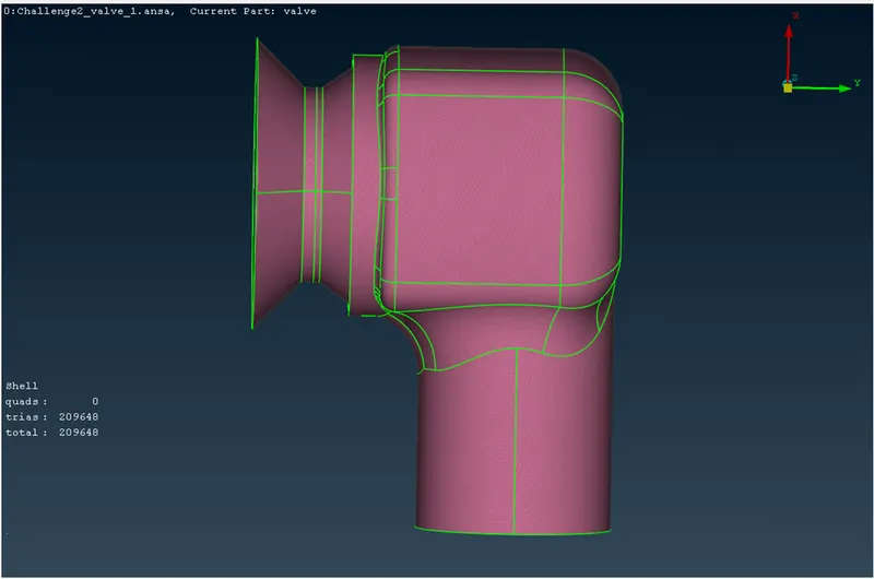
FOR 3 mm
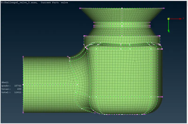
FOR 5 mm
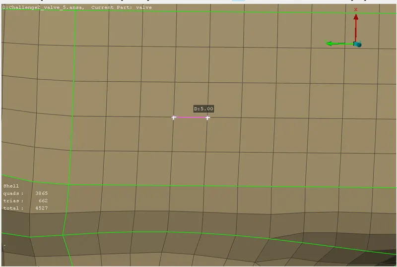
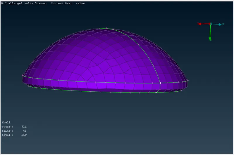
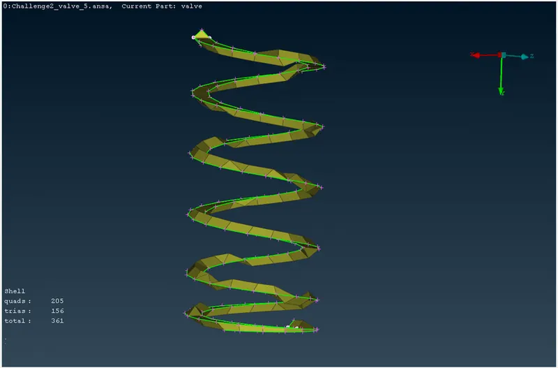
OUTCOME
- 5mm mesh length is not retained the shape of the model especially in smaller surfaces in the outer casing and spring and valve head.
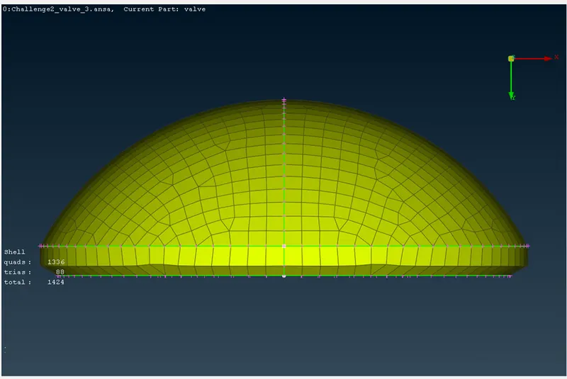
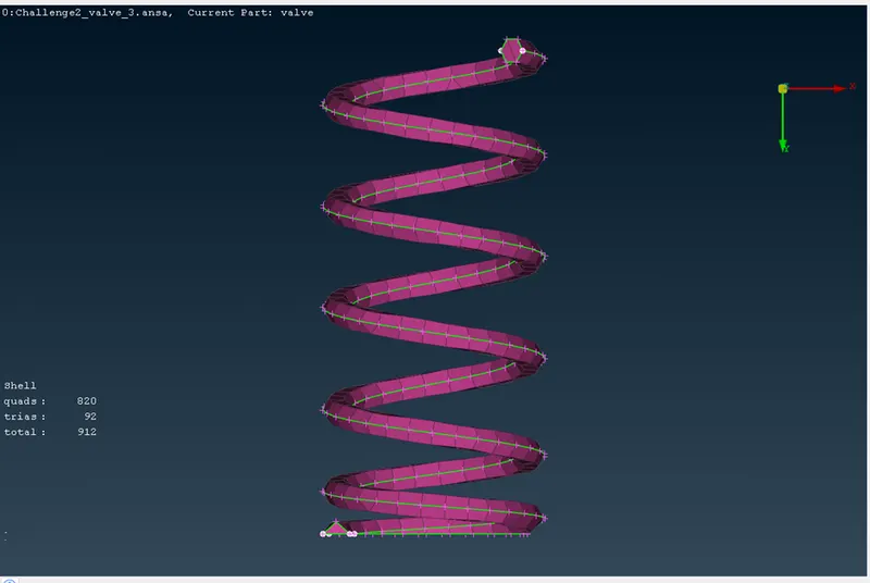
- 3mm mesh length gives retains much better shape of the outer casing but not of the spring and valve head
- 1mm mesh length retains the shape of the entire model.therefore it will give more accuracy
CONCLUSION
- Smaller mesh size(length) leads to increase in accuracy of results and also high computational time.
- So, we need to generate mesh that will lead to high accuracy and also less computational time
- This is done by giving small mesh length to small parts (in this case valve head and spring) i.e., 1mm.
- 3mm mesh length to outer casing.
- Smaller faces with greater mesh length lead to interference
- Geometries with very large mesh size loses its shape(spring and valve having 5&3mm mesh length)
- Mesh length should be such that the shape of the geometry is retained(1 mm)