Week 2 Challenge
1. 1. How will you assign Circular section to column?
Solution:
- Create a New File in Staad Pro.
- Now Create 2 nodes in Y direction.
- Now join the Two nodes using beam option to create the column Member.
- Now go the Properties tab.
- Select the Define command.
- Property dialog box will open.
- Enter the Diameter of the Circular Column.
- Select the define property from the list and Assign it to the member Created.
1. 2. How will you assign Unit system to a .std model file?
Solution:
- Open Staad Pro. Software
- Select New option in the left side menu.
- Enter the model information and select the location where you want to save the file.
- and last select the required unit system to apply it to model.
1. 3. What are the parameters to be specified while using “Bay Frame” option?
Solution:
- Open Staad Pro. Software
- Select New option in the left side menu.
- Enter the model information and select the location where you want to save the file.
- and last select the required unit system to apply it to model.
- Create it.
- Select the Structure Wizard & select the frame models in the model type.
- Double Click the Bay frame.
- Enter the values of all the parameters as per the requirement and apply it.
1. 4. Name few codal standards incorporated in STAAD Pro software.
Solution :
There are material Codal standards has been provided in the STAAD Pro. Software.
Steel
Concrete
1. 5. How will you specify the design compressive strength for a RCC section?
Solution :
- Create a new file.
- Draw the member.
- Go to the design tab and select the concrete material.
- Select Define Parameters from the right side tab.
- Select the FC in the list of the open Dialog box.
- Enter the value and Add it then close the box
- Now Assign it to the member.
2. 1. State the “Input” steps involved in RCC design.
Solution:
- Create the Geometry in Geometry Tab.
- Then Specify the required Properties to the members which are crated in Properties Tab.
- Then In Materials Tab Create the required Materials and then assign it to the Geometry.
- Then Provide any specification required to the structure.
- Then Provide the Support to the Structure as per the required conditions.
- Then as per the Indian Standards Define the Load Cases then apply it to the respective members created.
- Then Give the Analysis command for the file created.
- Run the Analysis Check the Analysis have zero errors.
- After that Select the Design Tab then Define the Parameters as the required Design Then apply it to the whole structure.
2. 2. Explain the difference between Fixed and Enforced support condition in STAADPro.
Solution:
- Fixed Support:
- All the Translational Movement and Rotational Movement are Restrained.
- Enforced Support :
- In this support also All the Translational Movement and Rotational Movement are Restrained But It allows us to assign a support displacement Load if at all we want a node or joint to act like a fixed node with restraining all my movements but Still we want the support to displace Minimum.
3. 1. Explain the steps involved in analysis of a model using STAAD Pro sequentially.
Solution:
- Create the Geometry
- Specify the required Properties to the members which are crated .
- Create the required Materials and then assign it to the Geometry.
- Provide any specification required to the structure.
- Provide the Support to the Structure as per the required conditions.
- Then as per the Indian Standards Define the Load Cases then apply it to the respective members created.
- Then Give the Analysis command for the file created.
- Select the analysis Type as per the support conditions.
- Run the Analysis Check the Analysis have zero errors.
3. 2. Explain the two ways in which a structural framework/model can be created in STAAD Pro software.
Solution:
- Way 1 : Create the model by plac
- ing the Nodes by entering the positions of x,y,z.
- Way 2 : Create the Model frame using Bay Frame Option in Structure Wizard.
3. 3. Elaborate the different support conditions in STAAD Pro.
Solution:
- Fixed Support
- All the Translational and Rotational Moment are Restrained.
- Pinned Support:
- In this all the Translational moment are Restraint.
- Fixed Support :
- In This we can release the moments as per our requirements and define the spring values.
- Enforced :
- In this support also All the Translational Movement and Rotational Movement are Restrained But It allows us to assign a support displacement Load if at all we want a node or joint to act like a fixed node with restraining all my movements but Still we want the support to displace Minimum.
- Enforced But :
- In this as per the requirement conditions we can release the moments as per the needs and make the node or joint to act like fix but it will have the displacement Load.
3. 4. How will you extract the stress distribution for a staircase slab?
Solution:
- The Design of Staircase slab is done by Node placement
- The creation of plate is used in stair case
- BY using Generate mesh
- The stress distribution for the staircase slab is done by viewing color in the slab of the design.
3. 5. Explain the different ways to view SFD & BMD in STAAD Pro.
Solution:
Different ways to View the SFD and BMD :
First after analyzing go to post processing mode the there we can see the SFD and BMD.
or
Second After completing the analysis making the Design of the members, after that Design double click the Beam member there we can see the SFD and BMD.
Practical
1. Analyze the following structural elements and validate the results
A. Simply Supported Beam
a. A Simply supported beam with two point loads symmetrically placed
b. Span L = 20m
c. Load P = 50kN each
d. Both P located at 5m from each support
Solution:
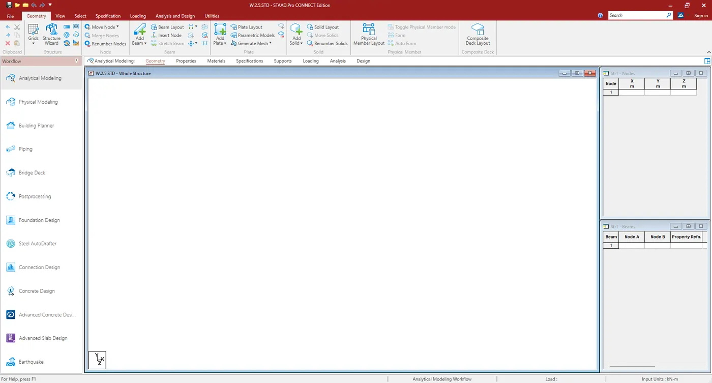
- Open Staad.Pro.
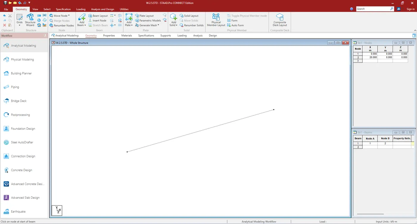
- Enter the two nodes value and join them.
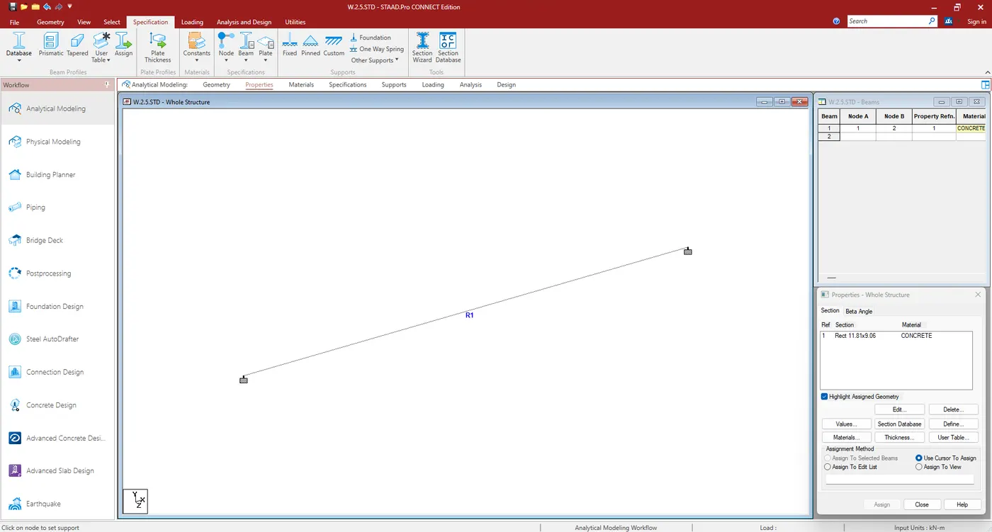
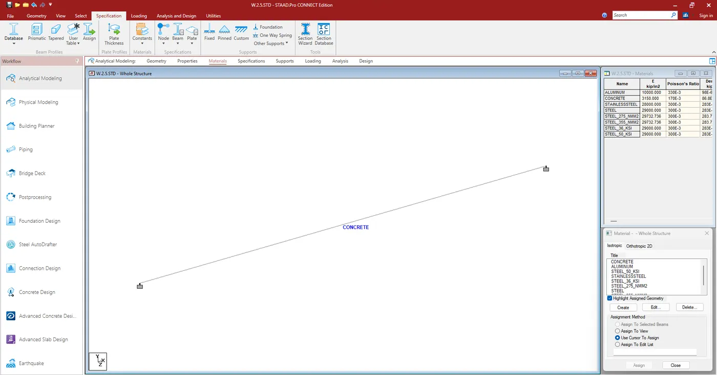
- Give the property to the beam and material.
- Now Define the point load and assign at 5 m from the origin.
- Now Give the Analyze command & Run Analyze.
- Got to Postprocessing mode.
</> <>< alt>
</> </> </> </> <> </> <> </> <> </> <><>>< /><> >< /><> ></> <><>></> <> <> > <>< alt>
- Give the vale to the nodes and join the nodes.
- Now Define and assign the property and material & support to the beam and the Support at the nodes.
- Now define the UDL and assign it to the beam.
- Now Define the Analyze command and run the analysis.
- Now go to postprocessing mode & see the results.