Week 2 Challenge
QUE:-1.1
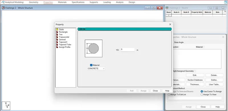
QUE.-1. How will you assign Circular section to column?
ANS:
- Go to properties in that select define property select circle and give the radius for the member and assign the defined circle to the member created.
QUE.-2. How will you assign Unit system to a .std model file?
ANS:
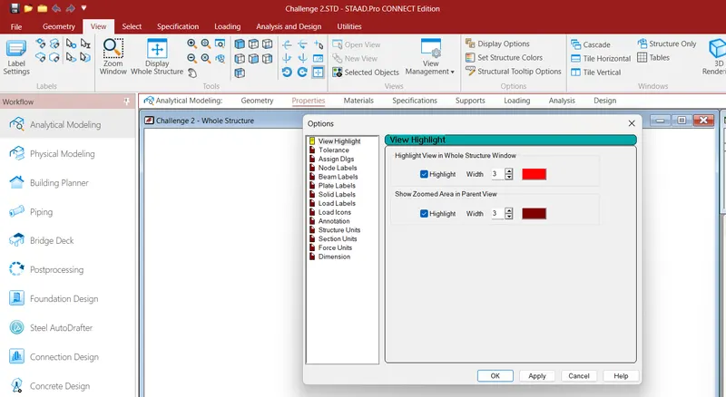
- Go to View Tab
- Select Display Option
- Check the units
QUE.-3. What are the parameters to be specified while using “Bay Frame” option?
ANS:
- Go to geometry tab
- By clicking on the Structural wizard option
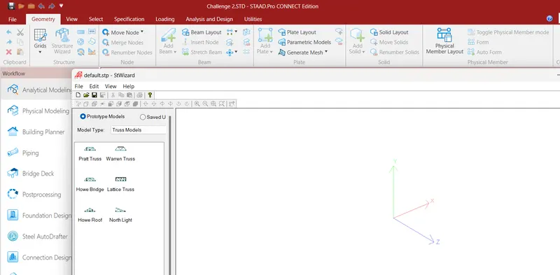
- Click on the frame model option.
- click on the Bay frame option.
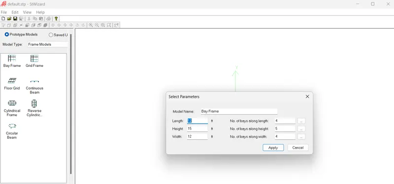
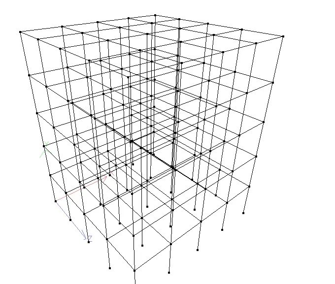
- Enter the parameters like the length , breadth , height and the bay frame along the length , breadth and height.
QUE.-4. Name few codal standards incorporated in STAAD Pro software.
ANS:- Codal standards are
- IS 456-2000
- IS 13920-2016
- IS 875-1987
- IS 800-2007
- IS 1893-2016
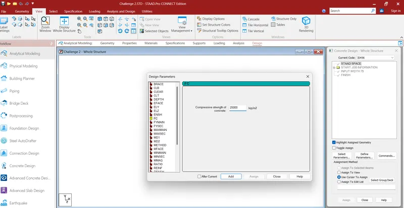
QUE.-5. How will you specify the design compressive strength for a RCC section.
ANS:-
- Go to design tab
- Select concrete
- Click on Define Parameters
- Click on FC and Input the Compressive strength of the concrete.
QUE:-2.1
QUE.-1. State the “Input” steps involved in RCC design.
ANS:- Steps involved in RCC design are
- Geometry
- Properties
- Materials
- Specification
- Support
- Loading and Load combinations
- Analysis
- Design

QUE.-2. Explain the difference between Fixed and Enforced support condition in STAADPro.
ANS:
- In STAAD support displacement loads cannot be applied to such models when the fixed type of support is specified
- For the ENFORCED BUT type there is no provision to specify a spring constant.
- The only choices which are built into the program are zero stiffness.
QUE:-3.1
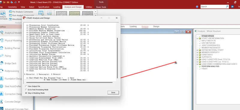
QUE.-1. Explain the steps involved in analysis of a model using STAAD Pro sequentially.
ANS:
- Go to the Analysis Tab
- Select Define Commands
- A new Window will open
- Click on Performed Analysis
- Click on add and close
- Click on Run Analysis
- Save the File
- Agian Run
- A new window PopUp
- Check any Errors.
- Resolve If Any Errors using Commands and Put Plane as space.
- Now Again Click on run Analysis.
QUE.-2. Explain the two ways in which a structural framework/model can be created in STAAD Pro software.
ANS: - The two ways in which a structural framework/model can be created in STAAD Pro software are:
- Node by Node method.
- Structure wizard method.
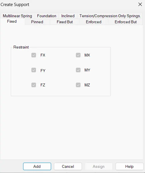
QUE.-3. Elaborate the different support conditions in STAAD Pro..
ANS:
- Fixed
- Pinned
- Fixed But
- Enforced
- Enforced But
- Multilinear spring
- Foundation
- Inclined
- Tension/Compression only springs
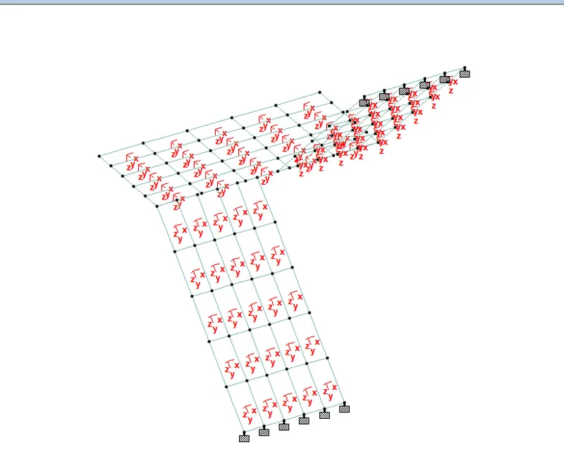
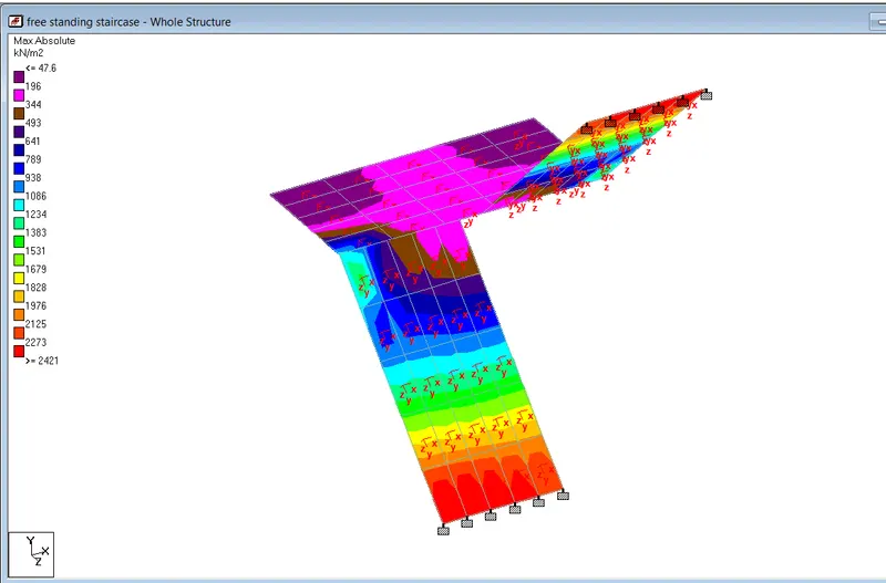
QUE.-4. How will you extract the stress distribution for a staircase slab?
ANS:
- The Design of Staircase slab is done by Node placement
- The creation of plate is used in stair case
- BY using Generate mesh
- The stress distribution for the staircase slab is done by viewing colour in the slab of the design
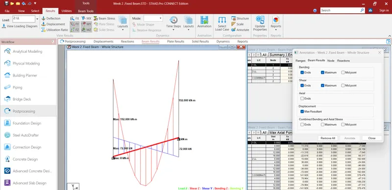
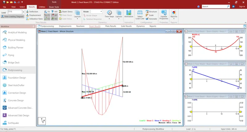
QUE.-4. Explain the different ways to view SFD & BMD in STAAD Pro.
ANS:
- After completing the design and running the analysis software will provide the BMD and SFD
- After the analysis click on Post processing mode and click OK
- Go to deflection command and click on beam result
- In reaction command click the beam deflection
Practical
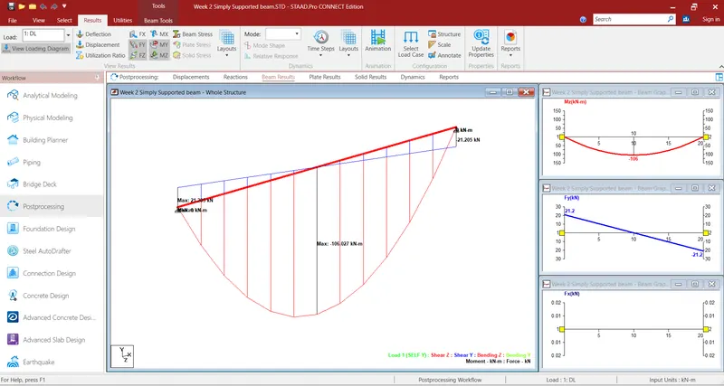
1. Analyze the following structural elements and validate the results
A. Simply Supported Beam
a. A Simply supported beam with two point loads symmetrically placed
b. Span L = 20m
c. Load P = 50kN each
d. Both P located at 5m from each support
ANS:-
Procedure:-
- Open Stadd Software
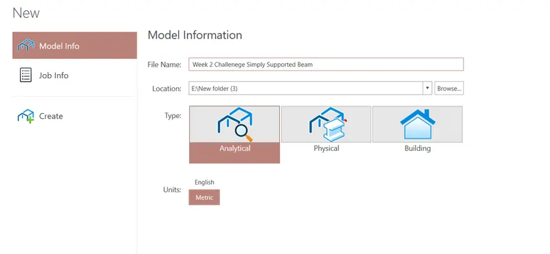
- Create new Model
- Select Matric
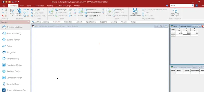
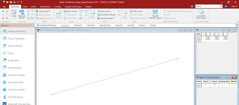
- Go to the Geometry and give ditance of 0-20 m in Table
- Go to property and add property of beam
- Choose rectangle and material concrete.
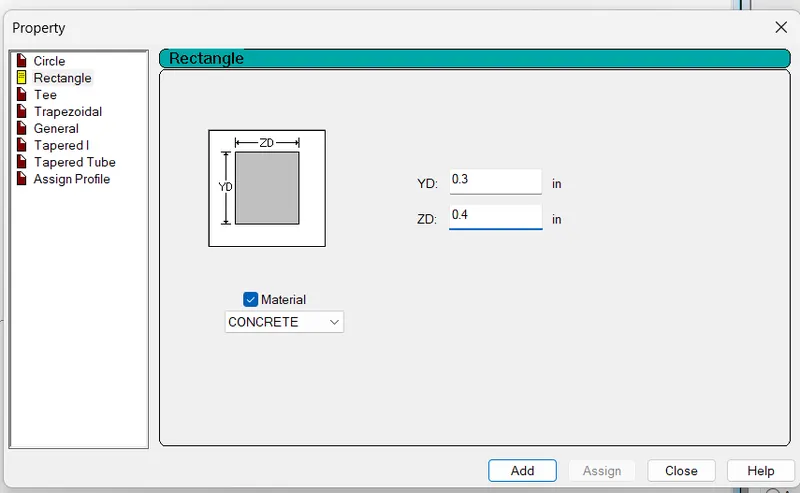
- Assign the Property to the view.
- Go to Support tab and create simply support (Pinned support) and add it. Then assign it
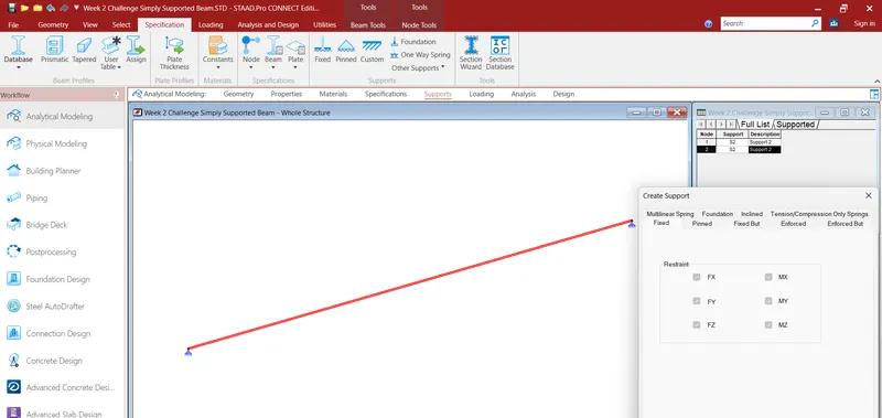
- then create dead load and live load case. After that create a load combination.
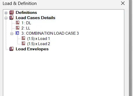
- Go to analysis tab and select analysis command and do perform analysis
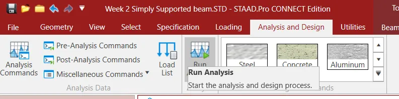
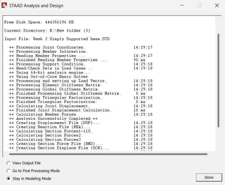
- Run the analyis
B.Fixed Beam
a. Span L = 16m
b. Uniformly Distributed Load w=9kN/m
ANS:-
Procedure:-
- Open Stadd Software
- Create new Model
- Select Matric
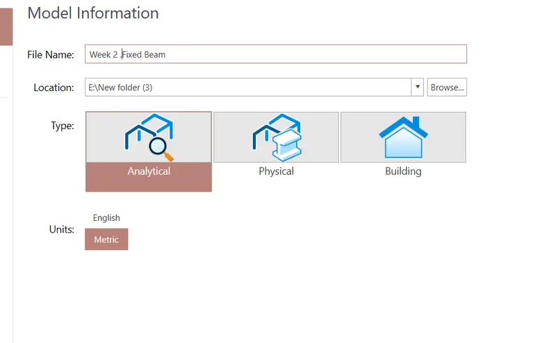
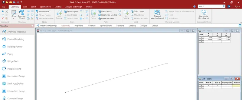
- Go to the Geometry and give ditance of 0-16 m in Table.
-
Click to add beam and join those node
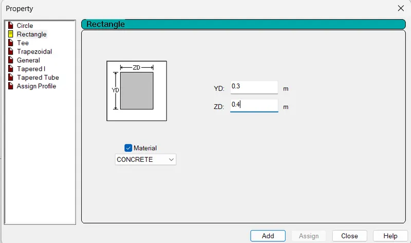
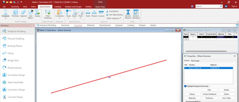
- Go to property tab and define concrete beam.
- I assumed a rectangular beam of size 300mm X 400mm.
- After define click to add.
- Then click assign to view and click yes
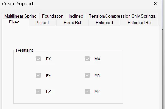
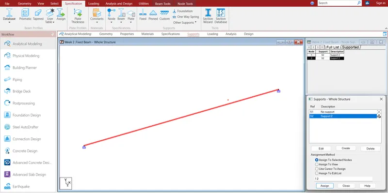
- Go to Support tab and create fixed support and add it. Then assign it
- Then go to loading tab and click to add and then create dead load and live load case. After that create a load combination.
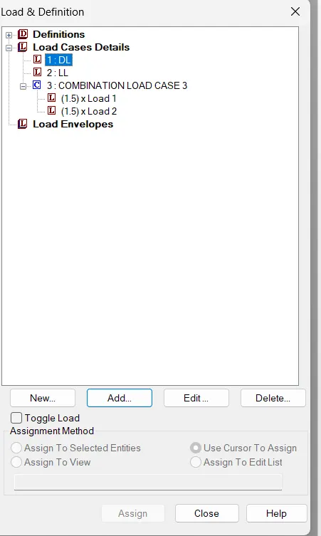
- Under Dead load case click to add then add selfweight
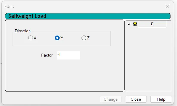
- Then click to Live load case and click to add. Then go to member load select Uniform force and input the data as -9 KN/m under Y axis,Finally assign both selfweight and nodal load.
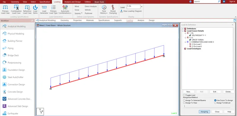
- Go to analysis tab and click to analysis and select perform analysis.