Week 2 Challenge
AIM OF THE EXPERIMENT:
To Define all loads to be applied in the abutment of the bridge as per IRC 6 and mention the clauses.
Check for overturning and sliding of 4 m height of Abutment (from ground level), embedded 2 m in ground.
THEORY:
Abutment:-An abutment is the substructure at the ends of a bridge or culvert supporting its superstructure. Single-span bridges have abutments at each end which provide vertical and lateral support for the span, as well as acting as retaining walls to resist lateral movement of the earthen fill of the bridge approach. Multi-span bridges require piers to support ends of spans unsupported by abutments.
Stability Checks for Designing of Abutment:
- Over-Turning check
- Sliding Check
- Bearing check
Solution:-
Different kinds of loads acting on the Abutment are:-
- Dead load/Self weight – It is the weight of the structural components like deck slab, girders, Pier/abutment cap, pier shaft/abutment stem (excluding crash barrier, wearing coat, Light pole) in a structure. It acts in vertically downward direction.
Clause 203 of IRC: 06-2017.
- Super imposed dead load - It is the weight of Crash barrier, wearing coat, Light pole over the deck of the superstructure. It acts in vertically downward direction.
Clause 206 of IRC: 06-2017.
- Earth pressure – It is the weight of soil resisted by the pier shaft or abutment stem. It acts in horizontal direction.
Clause 214 of IRC: 06-2017.
- Live load – It is the load of the traffic above the deck due to movement of vehicles. It acts in vertically downward direction.
Clause 204 of IRC: 06-2017.
- Braking load - It is a load induced when brakes are applied in a vehicle. It acts in horizontal direction.
Clause 211 of IRC: 06-2017.
- Temperature load – This load is considered due to fluctuation in temperature of the location where the bridge is built. It acts in horizontal direction.
Clause 215 of IRC: 06-2017.
- Wind load – It is a load exerted by the wind at that particular location where the bridge is built in horizontal direction & vertical direction. Force in vertical direction tends to lift the structure and force in horizontal direction tends to push the structure.
Clause 209 of IRC: 06-2017.
- Seismic load – A force due to earthquake acting in horizontal directions and vertical direction. Force in vertical direction tends to lift the structure and force in horizontal direction tends to push the structure.
IS-1893-2017
- Water pressure – It is a force exerted by the water in a stream/river to pier shaft/ Abutment stem in lateral direction.
Clause 210 of IRC: 06-2017.
Check for overturning and sliding:
Given Data:
- Top width of the retaining wall = 400mm
- Bottom width of Retaining wall = 650mm
- Size of foundation = 3650 x 700 mm
- Width of toe = 1000mm
- Width of heel = 2000mm
- Length of Retaining wall = 1m
Concrete & Steel Data
- Grade of Concrete = M30
- Grade of Steel = Fe500
- Unit Weight of Concrete = 25kN/m3
Soil Data
- Unit Weight of Soil = 20kN/m3
- Angle of internal friction of Soil = 50 deg
- Angle of inclination of wall from vertical face = 90 deg
- Angle of friction between wall & soil = 20 deg
- Safe Bearing Capacity of Soil = 200kN/m3
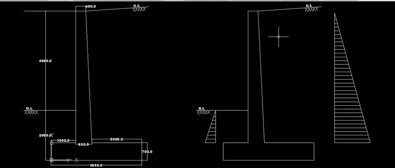 .
.
Coefficient of active earth pressure, Ka = (1-sinΦ)/ (1+sinΦ) = (1-sin50) / (1+sin50) = 0.133
| Sl. No. | Description of Load | Magnitude of Load (KN) | Distance of C.G. (m) | Moment about C.G. (KN-m) |
| 1 | Wt. of Stem wall | (0.4+0.65) x 5.35 x 25 = 140.44 KN | 1 + [0.42+0.652 – (0.4 x 0.65)] / (0.4+0.65) = 1.307 m | 141.747 KN-m |
| 2 | Wt. of Base Slab | 3.65 x 0.65 x 25 = 59.313 KN | 3.65/2 = 1.825 m | 108.25 KN-m |
| 3 | Wt. of Earth fill over heel | [0.5 x (0.65-0.4) + 2] x 5.35 x 18 = 204.64 KN | 1.65 + [22+2.152 – (2 x 2.15)] / (2 + 2.15) = 2.692 m | 550.9 KN-m |
| 4 | Wt. of Earth fill over toe | 1.55 x 1 x 18 = 27.9 KN | 1/2 = 0.5 m | 13.95 KN-m |
| ΣW = 432.293 KN |
| ΣM = 5772.947 KN-m |
Check against Overturning
Total Horizontal earth pressure over the abutment tending to over turn it = P = ½ x ρ x Ka x H2 = 0.5 x 18 x 0.133 x 5.352 = 34.261 KN
Acting at 4/3 from D
Total Overturning Moment, Mo = 34.261 x 4/3 = 45.6813 KN-m
Total Stabilizing moment = 5772.947 KN-m
Factor of Safety (against overturning) = 5772.947 / 45.6813 = 126.374 > 2,
Hence Safe
Check against sliding
Total Horizontal earth pressure over the abutment tending to overturn it = P = ½ x ρ x Ka x H2 = 0.5 x 18 x 0.133 x 5.352 = 34.261 KN
Total force opposing sliding = μ x ΣW = 0.5 x 432.293 = 216.15 KN
Factor of Safety (against sliding) = 5772.947 / 34.261 = 168.5 > 1.5,
Hence Safe.
2. AIM OF THE EXPERIMENT:-
- How to decide the boreholes location and its depth of exploration in case of shallow foundation?
- What all the parameters we need to get from the site/geotechnical investigation for design of the foundation?
Soil investigation is required for the following purposes – To know the allowable bearing capacity of foundation for proposed building. To know the depth and type of foundation for the proposed building. To know the allowable passive resistance for the foundation of proposed building. To know the type, grading and nature of soil. To know the ground water level.
Subsurface exploration in shallow foundation depends on the following parameters:
Nature of the soil and its parameters
Selection of depth suitable for the structure
Based on the following criteria the depth of foundation is fixed.
Based on embedment: As per IRC 78, if we don’t have any data the embedment should be minimum 2m from the ground level.
Based on scouring strata: We have to calculate the scour level from the hydrological data. The founding level should be kept 2m below scour level.
Based on rock strata: If we have a good rock at the top of the ground level itself then no need to go till 2m. We can place at the top as well.
Based on SPT: Standard penetration test is designed to provide the geotechnical information of the soil. It provides a measure of penetration resistance.
The adequate number of bore holes and sufficient depth is critical to gather enough data for the design and construction substructures as foundation, abutments, retaining walls, embankments.
- Borehole numbers should be enough to find out soil strata variations at the particular site or location.
- Borehole should be casted depending upon the area of construction of site, practically on a plane terrain, at least 3 boreholes should be placed at a site with the offset of 30 - 50 m intervals.
- Bore hole should be placed at the heaviest chances of loading, in bridges it means at every position of pier and abutment.
- Quality and depth of boreholes should keep undisturbed so that the detail of each strata at the site can be analysed most precisely.
- In the case of very dense materials or bedrock, the minimum depth of borehole is 6m whereas usually 10m depth hole is dugged out.
- Borehole should drill and carry at least 3m of depth into the bedrock.
- For dense, coarse-grained soil and very stiff clays, extend boring depth up to a range of 5-6m to corroborate that soil layer thickness is sufficient.
- Primarily the depth of borehole must be 1.5 times of the width of the foundation.
PARAMETERS OF THE SITE OF GEOTECHNICAL INVESTIGATION:-
- Depth of soil strata
- Bulk density (γ-bulk)
- Dry Density (γd)
- moisture content
- Gradation of soil (IS Classification)
- silt factor
- Liquid limit
- Plastic Limit
- Plasticity Index
- Specific Gravity
- Swelling Index
- Cohession
- Void ratio & porosity
- Angle of internal friction
- Depth of water table
- SPT (N Value)
Various types of soil are as follows:
- Sandy soil
- It consists of small particles of weathered rock. Soil particles of this soil ranges from 0.075mm to 4.75 mm. This type of soil is very good for the drainage system. Sandy soil is usually by the breakdown or fragmentation of rocks like granite, limestone and quartz.
- It has high porosity and cohesion value is 0. Strength is due to interlocking of granular particles. This soil has highly friction property.
- Silt soil
- Silt soil particles are much smaller than the sandy particles and it is made up of rock and other mineral particles, which are smaller than sand and larger than clay. It particles ranges from 0.075 mm to 0.002 mm.
- This soil has cohesion both C- Φ value.
- Clay soil
- Clay soil is the smallest particles among the other two types of soil. The particles in this soil are tightly packed together with each other with very little or no airspace. This soil has very good water storage qualities and makes it hard for moisture and air to penetrate into it.
- This soil has high cohesion and friction Φ value is 0. And it particle sies ranges less than 0.002 mm.
- Loamy soil
- It is the combination of sand, silt and clay such that the beneficial properties of each are included. For instance, it has the ability to retain moisture and nutrients, Hence, it is more suitable for farming.
- Rocky soil
- Rocky soil is the result of the ground beneath your garden shifting and pushing rocks upwards towards the earth’s surface. Generally, rocks such as limestone, bedrock, and sandstone have substantially high bearing capacities.
Criteria for the selecting the shallow foundation:
- Selection criteria for foundation depend on two factors, i.e. factors related to ground (soil) conditions and factors related to loads from the structure.
- Soil bearing capacity is one of the most crucial criteria that affect the selection of the appropriate type of foundation. Decision can be made to choose shallow or deep foundation based on the soil bearing pressure.
- An allowable bearing pressure of at least 100kN/m^2 i.e 10 ton/m^2 shall be considered. However, higher structures can consider a raft foundation.
- For selecting the founding level of the foundation, the SPT value also plays a major role. The N value should not be less than 10.
- Allowable settlement for the isolated footing as per the Indian standard is upto 50 mm.