Week 2 Challenge
AIM:
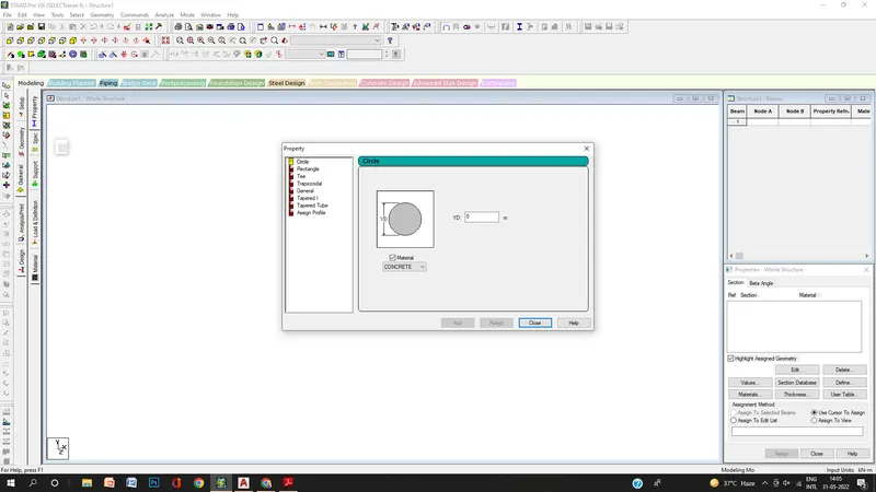
1.1 How will you assign Circular section to column?
Introduction:
- Column are the vertical member in the Structure that can be of varying size in dimensions
- The circular section of column is provided at the upper floor of the building for the better load carrying and access purpose
Procedure:
- Create the model in the staad pro that can be a column
- Go to properties in that Define parameters
- Assign the circular shape of the column
- The radius of the circular is given
1.2: How will you assign Unit system to a. std model file?
ANS:
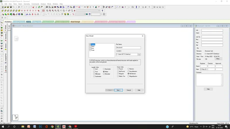
- To Assign unit system in the staad pro
- Go to file menu and then settings
- open the structural settings
- Change the dimensions as the required units
1.3: What are the parameters to be specified while using “Bay Frame” option?
ANS:
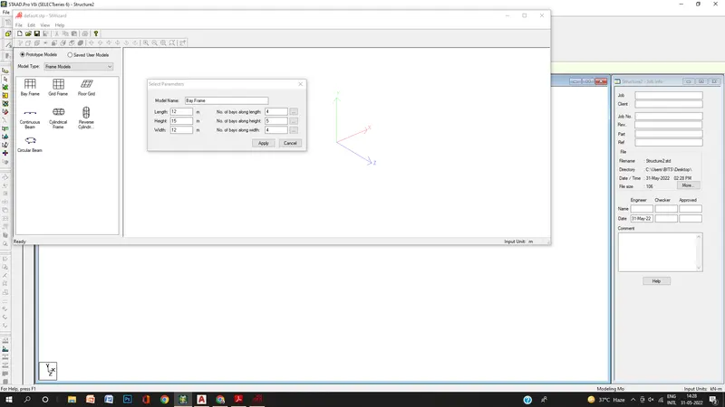
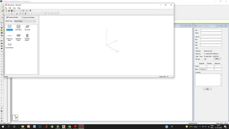
- To create the parameter of the design by Bay frame
- By clicking on the Structural wizard option
- Click on the frame model option
- click on the Bay frame option
- Enter the parameters like the length, breadth, height and the bay frame along the length, breadth and height
1.4: Name few codal standards incorporated in STAAD Pro software.
ANS:
- In Staad pro the Codal standard is incorporated for Steel, Concrete, Aluminum.
- For the Steel the codal provision are IS 800, IS 800: 2007, IS 800:2007 WSD, IS 801
- For the concrete Codal provision are the IS 456 and IS 13920 for the Seismic Design
1.5: How will you specify the design compressive strength for an RCC section?
ANS:
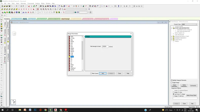
- Go to the Design option
- Click on the define parameter
- In the design Parameter the FYLD Compressive strength of RCC section is Given as 25000 KN/m^2
2:1: State the “Input” steps involved in RCC design.
ANS:
Steps Involved in RCC design are
1. Geometry: The Node location and the node spacing are given
2. Properties: Specify the Sectional properties of the section
3. materials: Specify the properties of the material
4. Specifications: The specifications are given
5. Support: The end support is to be given
6. Loading: Need to provide the loading pattern and the loading combination
7. Analysis: Need to Analysis the modal and all the Input Specification are Given
8. Design: Finally, the Design are to be done
2:2: Explain the difference between Fixed and Enforced support condition in STAAD-Pro
ANS:
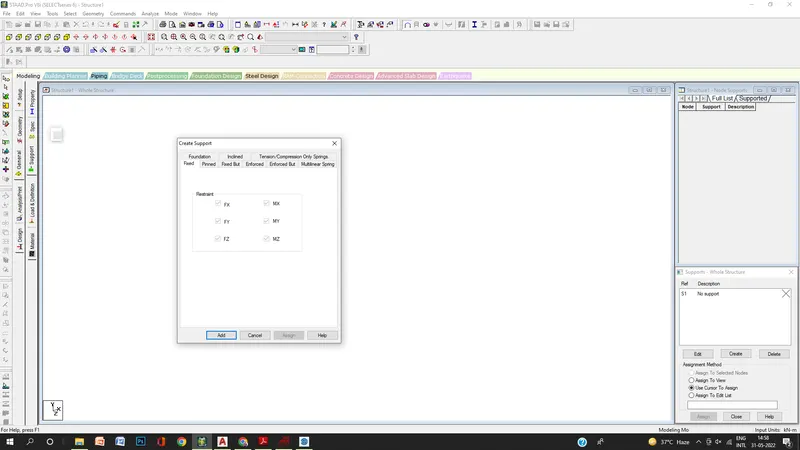
- In STAAD, support displacement loads cannot be applied to such models when the FIXED type of support is specified.
- For the ENFORCED BUT type, there is no provision to specify a spring constant.
- The only choices, which are built into the program, are - zero stiffness
3:1. Explain the steps involved in analysis of a model using STAAD Pro sequentially.
ANS:
The steps involved in analysis of a model are
- Before Analysis the model the load pattern and the load combination are to be provided to the model
- Then go to Analysis option
- Define Command
- Select the data for the analysis of the model by perform analysis, P delta analysis, Nonlinear analysis
- It depends upon the support conditions
3.2. Explain the two ways in which a structural framework/model can be created in STAAD Pro software.
ANS:
The two ways to model a structural framework is
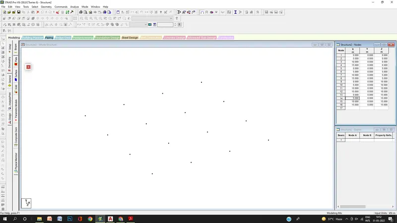
1. Creating model by Node by Node
2. Creating model by Bay frame by
3.3. Elaborate the different support conditions in STAAD Pro.
ANS:
3.4. How will you extract the stress distribution for a staircase slab?
ANS:
- The Design of Staircase slab is done by Node placement
- The creation of plate is used in stair case
- BY using Generate mesh
- The stress distribution for the staircase slab is done by viewing color in the slab of the design
3.5. Explain the different ways to view SFD & BMD in STAAD Pro.
ANS:
- After completion of the Design the staad pro will automatically provide the BMD & SFD
- By Entering to the Post processing process click on ok
- By clicking the beam results check the shear force Fx and bending moment in Mz
Practical
1. Analyze the following structural elements and validate the results
A. Simply Supported Beam
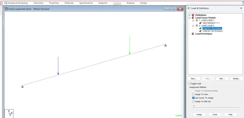
a. A Simply supported beam with two-point loads symmetrically placed
b. Span L = 20m
c. Load P = 50kN each
d. Both P located at 5m from each support
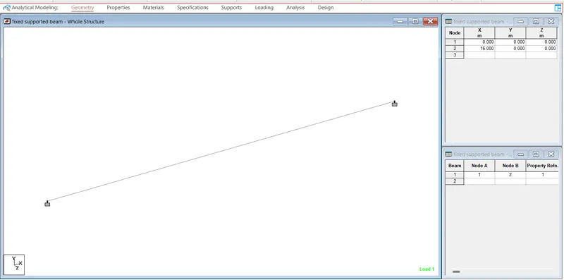
2. Fixed Beam
a. Span L = 16m
b. Uniformly Distributed Load w=9kN/m
1.
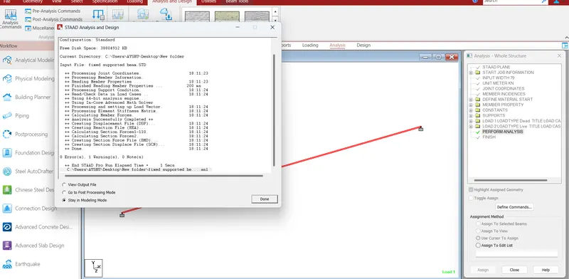
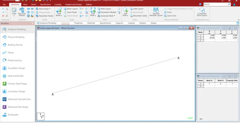
Aim: create the simply supported beam in Staad pro and analysis
procedure:
step-1
Geometry:
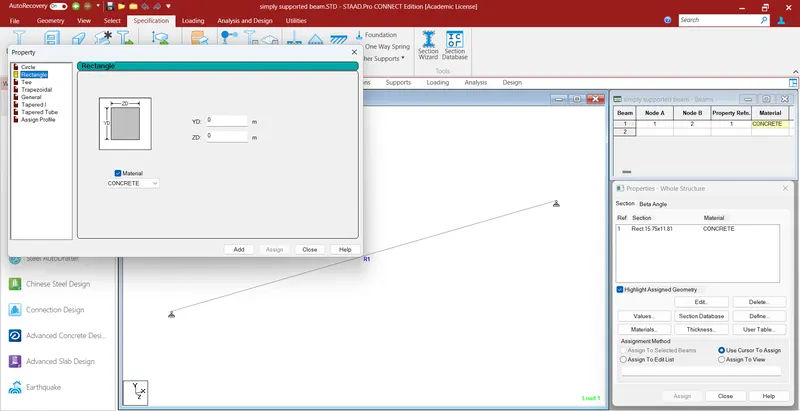
step-2
properties:
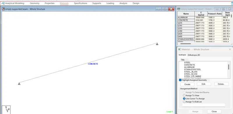
Step-3
Material:
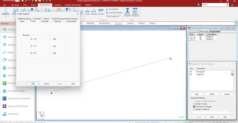
step-4
support creation :
Step-5
Loading
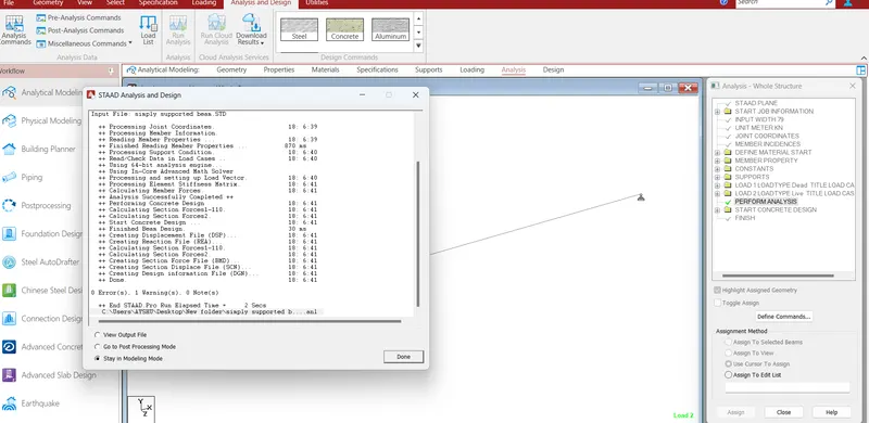
Step-6
Run analysis
Aim: create a fixed supported beam and analysis in Staad pro.
Procedure:
step-1
geometry
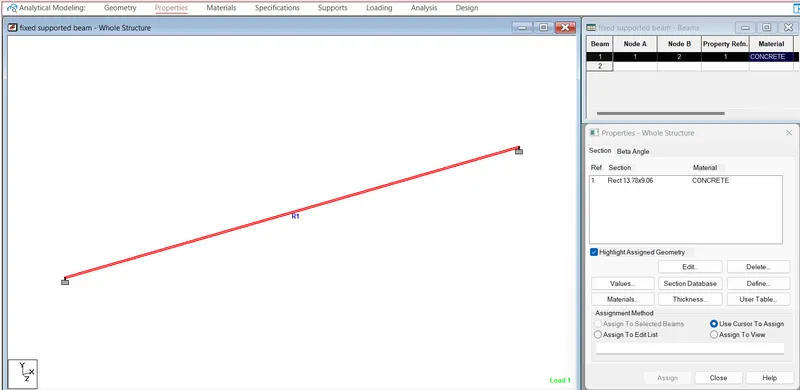
Step-2
Properties:
Step-3:
Material:
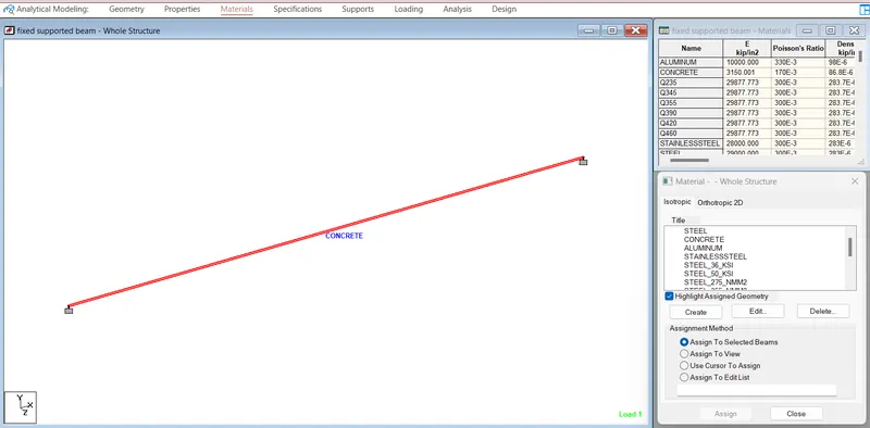
step-4:
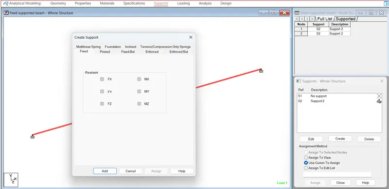
step-5
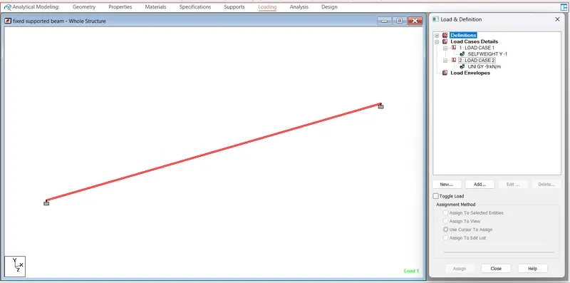
step-6