Week 6 Challenge
Aim: To determine pipe load acting on bridge and analyze accordingly in Staad.Pro.
Introduction:
The objective is to calculate the pipe load from the given data manually and attempt the same in Staad.Pro for the bridge and analyze the results and effects on the structure.
The Illustrated bridge is a steel girder bridge spanning of 24.0m in length and width of 3.0 m utilizing to provide the path for travelling the liquid in the pipes connected to it having sizes of diameter 700 mm and 200 mm made up of Ductile Iron.
Given Data (for calculation):
Width of Bridge = 3.0 m
Location = Bank of River Narmada
Diameter of Pipe 1 = 700 mm NB DI
Diameter of Pipe 2 = 200 mm NB DI
Length of Bridge = 24.0 m
Assumption:
Type of liquid in the Pipe = Water ( Density of 10 KN/m3)
Diameter of column = 1000 mm
Height of column = 1500 mm
Size of Cross Beam = 0.35m X 0.45m
Thickness of deck sheet = 0.2 m = 200 mm
All the dimensions are taken from the figure by center line of the member only.
Procedure:
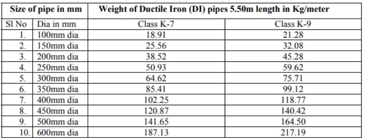
Table 1: Self weight of Ductile Iron Pipe
From the table 1, value of weight of pipe per meter is known and calculated as,
Weight of Pipe 1 (700 mm diameter NB DI) = 271.19 kg/m (Considering D.I. of Class K-9 equal to 600mm pipe) (Heaviest all among)
Weight of Pipe 2 (200 mm diameter NB DI) = 45.28 kg/m (Considering D.I. of Class K-9) (Heaviest all among)
Calculating the load on bridge,
- (i) For 700 mm diameter pipe = 271.19 kg/m = 2.712 KN/m
The water load due to water in pipe 1 = Area x Unit weight = pi X (700/2)2 X 10 = 3.848 KN/m
Total Load of Pipe 1 = 2.712 + 3.848 = 6.56 KN/m
- (ii) For 200 mm diameter pipe = 45.28 kg/m = 0.453 KN/m
The water load due to water in pipe 2 = Area x Unit weight = pi X (200/2)2 X 10 = 0.3142 KN/m
Total Load of Pipe 2 = 0.453 + 0.3142 = 0.7672 KN/m
Computer Proficiency:
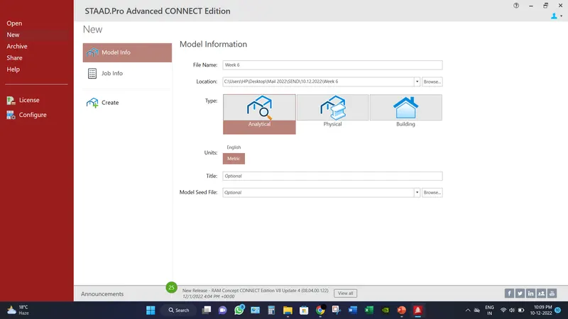
- Create a model by putting the necessary inputs as file location, units etc.
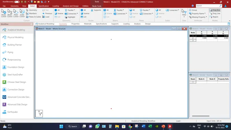
- Create two nodes (x,y,z) represents as (0,0,0) & (0,1.5,0).Because the height of column is assumed to be 1.5m.
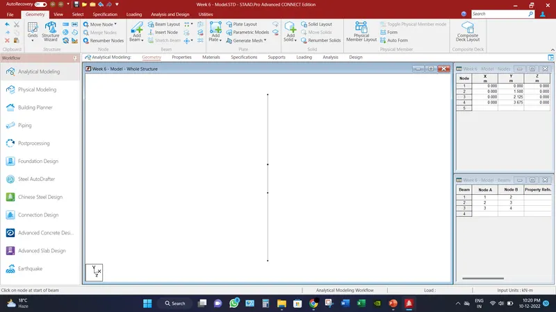
- Create another two nodes as (0,2.125,0) & (0,4.75,0). According to the question making steel columns. Click on Add beam option from Geometry tab, and connect all the nodes.
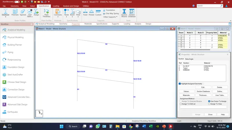
- Define the size of the pier as mentioned above and assign to the selected beams.
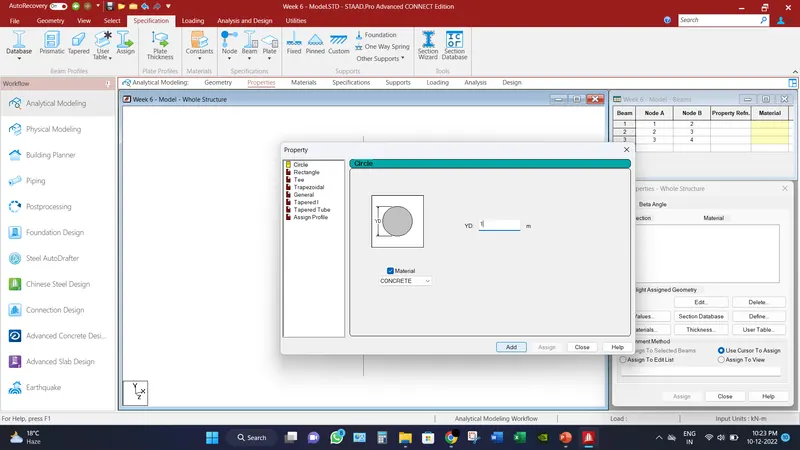
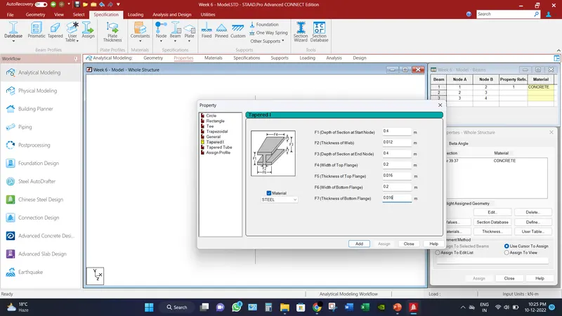
- Define all the sections of mentioned in the questions. For an instance, tapered section is provided by the dimension as top and bottom flange of 200 mm width and thickness of 16 mm and depth of 400 mm and web thickness of 12 mm. Refer the image below.
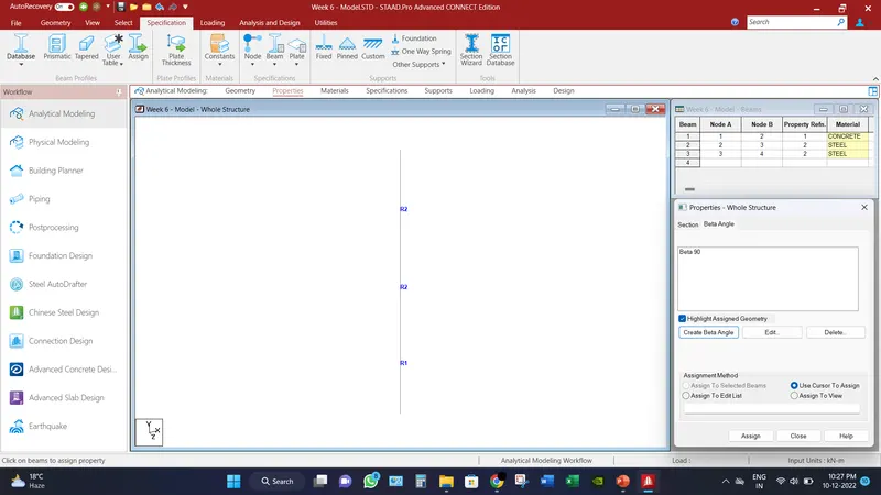
- Create the beta angle of 90 degree and angle 180 and provide to the sections which are necessary.
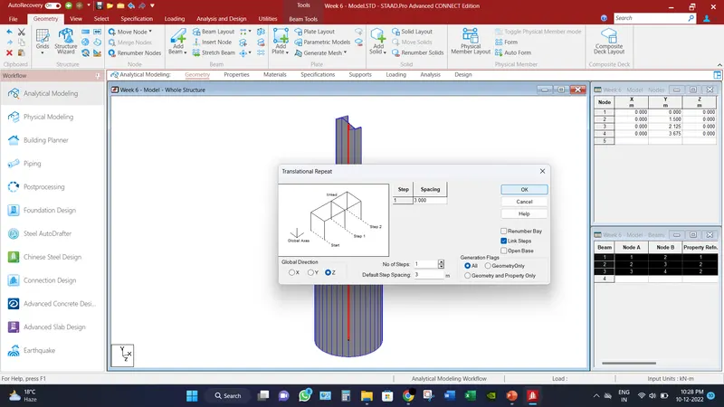
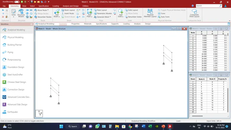
- Replicate the assembly into 3m into z direction and connect the nodes to form the portal of bridge.
- And for the other section is imported from the sectional database, such as ISMB250, ISMB100, etc. and define the RCC beam of size mentioned above. Refer the image below.
- Transitional repeat the same assembly into the 24.0 m distance in x direction.
- Connect the node in order to make girders of bridge and assigning the section of different part of bridge accordingly.
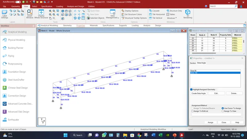
- Divide the girder into 8 parts and connect the mid girder and after assigning the sections, replicate that assembly into all the nodes according to question.
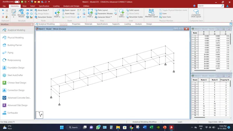
- According to questions, add the longitudinal bracing by add beams option and mirror the half portion of bracing by mirror option and assign the sections accordingly.
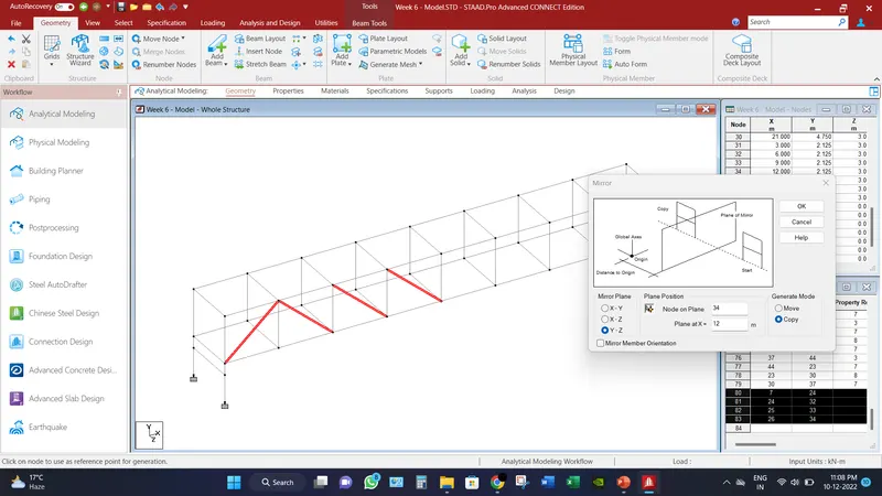
- In the same manner, model the bottom bracings according to question.
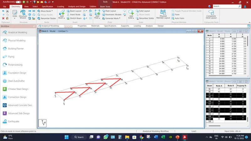
- In order to create mesh, connect the nodes and provide the division of mesh size in 500 mm X 500 mm. and assign the thickness of plate as mentioned above.
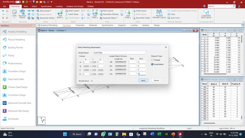
- Replicate the formed plates in order to make deck slab. Refer image below.
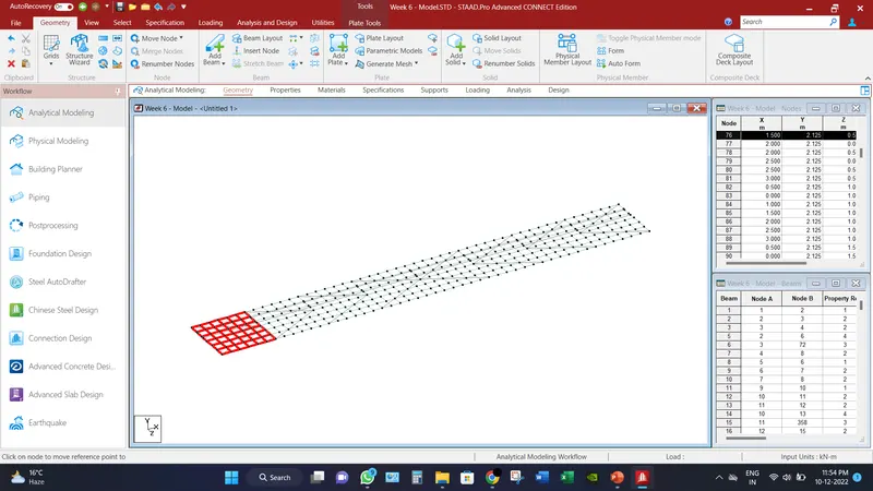
- 3D view of the modelled bridge is mentioned below with and without deck slab.
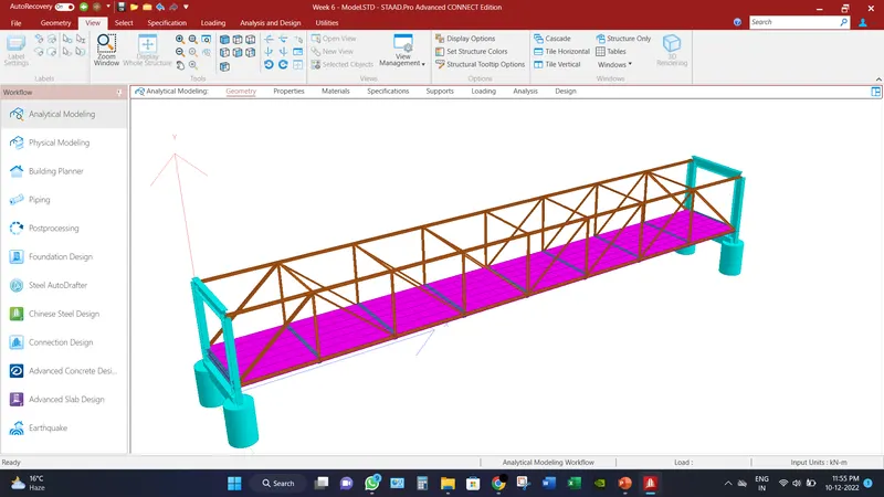
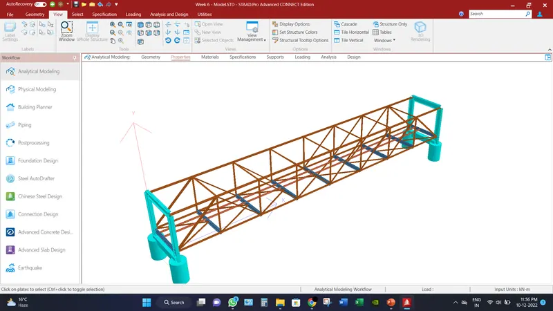
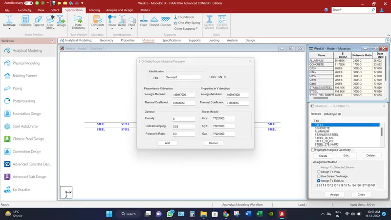
- In order to provide the loading to the pipe load, a beam need to be casted with zero density as the self-weight of pipe is already calculated in manual calculation.
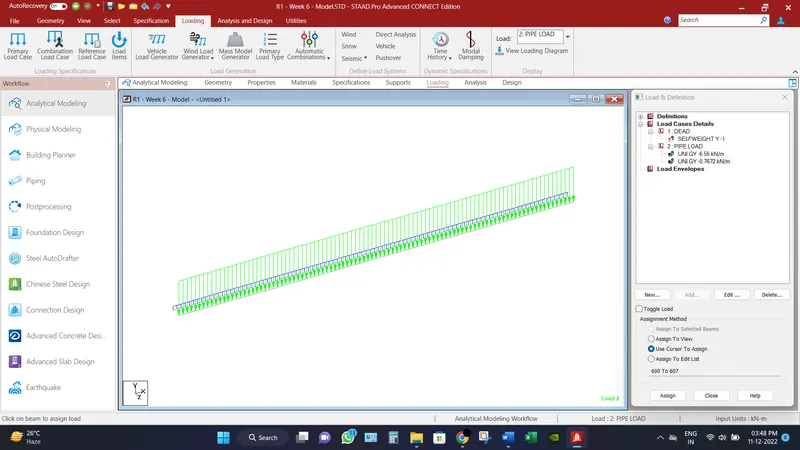
- Go to loading, add two load cases as Dead & Pipe load, in Dead load case add self weight as factor of -1. And Pipe load as member load of intensity of values mentioned above and assign loading accordingly.
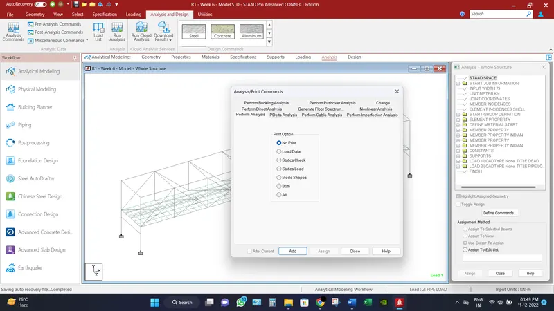
- Go to analysis tab, and choose analysis commands and select add button.
Analytical Results:
Bridge has been analyzed and check for different load combination and different displacement for different scenarios has been record.
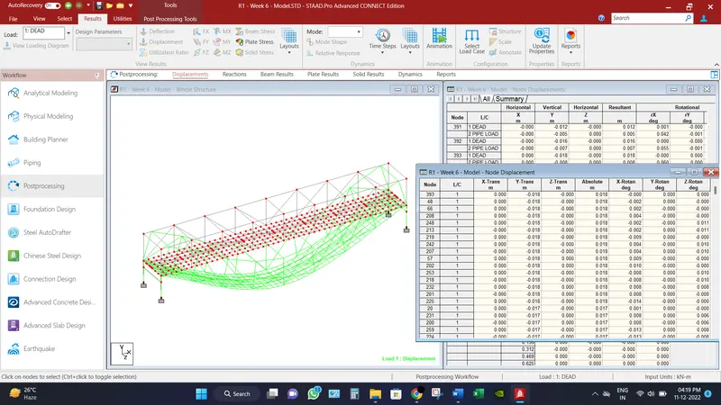
Maximum node displacements is recorded as 18 mm.
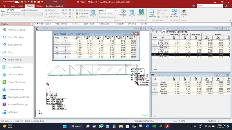
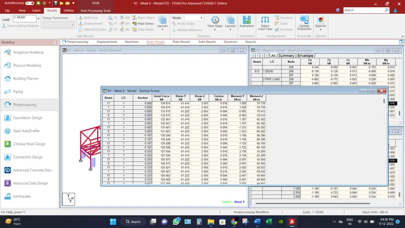
Maximum Base reactions are recorded axial force as 134.874 KN and moment as 70.739 KN-m.
Maximum shear force recorded in beam in Fy direction is 41.414 KN.
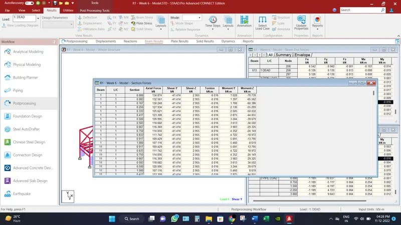
Maximum Moment recorded in beam in Mz direction is 70.739 KN-m.
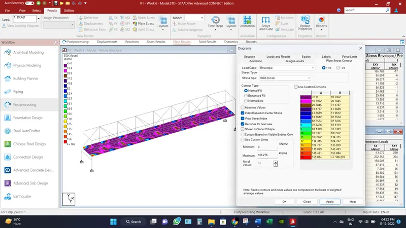
Maximum Shear in SQX (local) direction for deck slab is recorded as 166.276 KN/m2.
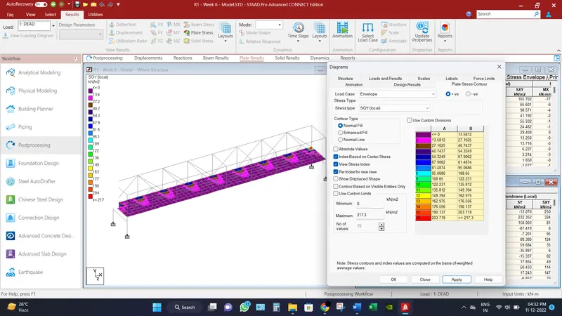
Maximum Shear in SQY (local) direction for deck slab is recorded as 217.3 KN/m2.
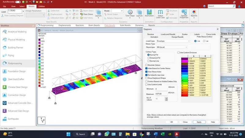
Maximum Moment in MX (local) direction for deck slab is recorded as 8.0713 KN-m/m.
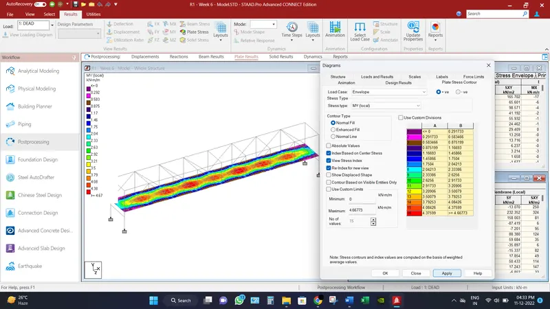
Maximum Moment in MY (local) direction for deck slab is recorded as 4.668 KN-m/m.
Conclusion:
Different results have been found under the Pipe loads,
Maximum node displacements is recorded as 18 mm.
Maximum Base reactions are recorded axial force as 134.874 KN and moment as 70.739 KN-m.
Maximum shear force recorded in beam in Fy direction is 41.414 KN.
Maximum Bending Moment recorded in beam in Mz direction is 70.739 KN-m.
Maximum Shear Force in SQX (local) direction for deck slab is recorded as 166.276 KN/m2.
Maximum Shear Force in SQY (local) direction for deck slab is recorded as 217.3 KN/m2.
Maximum Moment in MX (local) direction for deck slab is recorded as 8.0713 KN-m/m.
Maximum Moment in MY (local) direction for deck slab is recorded as 4.668 KN-m/m.