Week 2 Challenge
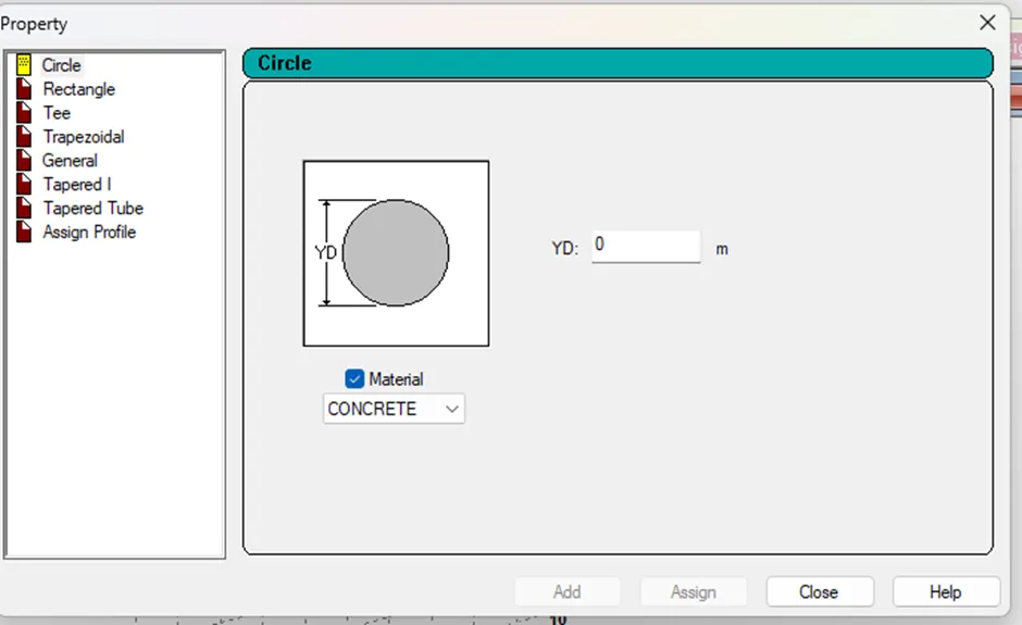
1.1 How will you assign Circular section to column?
Aim: To know the process of assigning circular section to column.
Procedure:
Create a column by inserting two nodes and joining them with a beam.
Go to general page control. Make sure you are in the property sub-page.
Select the column created.
From data area at the right of the screen, click on define.
There will be four different cross-sections to pick from
CIRCLE, RECTANGLE, TEE, TRAPEZOIDAL
Choose circle option.
Specify the diameter of the cross-section (YD). choose the material type from material list and click on add.
Now select the circle section added in the properties box.
Choose any assignment method and click on assign.
Result: The process involved in assigning circular section to column is explained.
1.2 How will you assign Unit system to a .std model file?
Aim: To know the process involved in assigning Unit system to a .std file.
Procedure:
There are two ways in which we can assign unit system.
In the beginning of a new project, we can assign unit system.
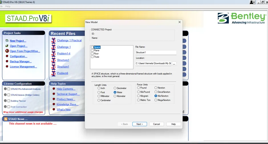
We can also assign units while creating the model.
From the ribbon, choose input units option.

The following dialog box appears.
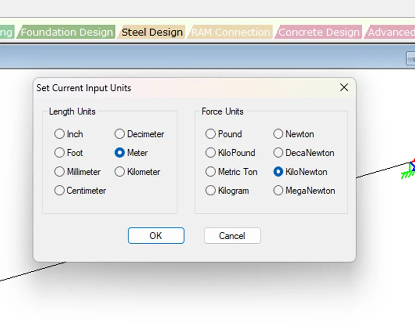
Select the units and click on OK.
Result: The process involved in assigning unit system to a model is explained.
1.3 What are the parameters to be specified while using “Bay Frame” option?
Aim: To list the parameters to be specified while using “Bay Frame” option.
Procedure:
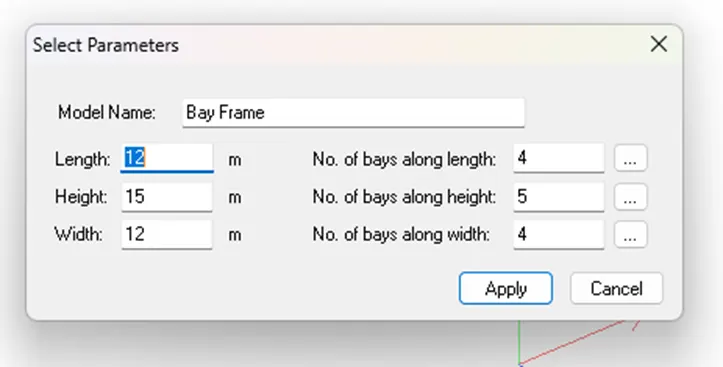
Parameters specified in Bay Frame are:
· Length
· Height
· Width
· Number of bays along length
· Number of bays along height
· Number of bays along Width
Result: The parameters to be assigned while using Bay Frame option are listed.
1.4 Name few codal standards incorporated in STAAD Pro software.
Aim: To name or list few codal standards incorporated in STAAD Pro software.
Procedure:
List of codal standards:
· IS 13920
· IS 456
· IS 800 2007 LSD
· IS 800 2007 WSD
· ACI 318 2011
· SP 63.13330.2012
· SP 16
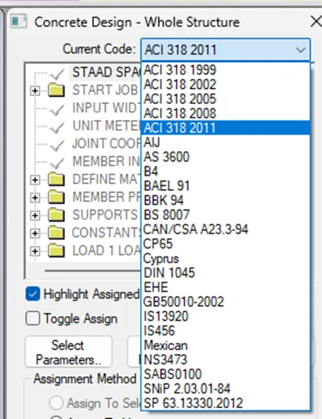
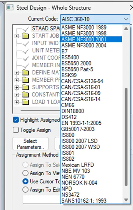
Result: Few codal standards incorporated in STAAD Pro software are listed.
1.5 How will you specify the design compressive strength for a RCC section?
Aim: To know the process involved in specifying the design compressive strength for a RCC section.
Procedure:
Go to Design tab in Commands menu.
Select concrete design.
Click on Define Parameters.
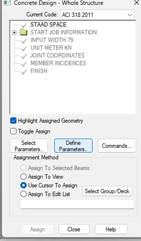
Now click on FC and enter the compressive strength of concrete value.
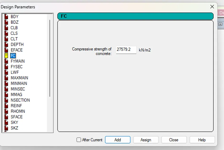
Click on add and close.
Assign the FC by using any assignment method.
Result: The process involved in specifying the design compressive strength for a RCC section is mentioned.
2.1 State the “Input” steps involved in RCC design.
Aim: To state the Input steps involved in RCC design.
Procedure:
Input steps involved in RCC Design:
· Creating Geometry
· Assigning properties
· Assigning materials
· Specifications
· Assigning supports
· Applying loads
· Run the analysis
· Design
Result: The Input steps involved in RCC design are stated.
2.2 Explain the difference between fixed and enforced support conditions in STAAD Pro.
Aim: To differentiate fixed and enforced support conditions in STAAD Pro.
Procedure:
Fixed condition: When the fixed type of support is specified, for those degrees of freedom which are to be treated as fully restrained, STAAD assumes the displacements to be known quantities whose value is zero. Hence, those degrees of freedom are not considered for the stiffness matrix, and their value is not calculated.
Enforced condition: Ehen the enforced type of support is specified, for those degrees of freedom which are to be treated as restrained, STAAD assigns a spring with a very high spring stiffness-translational stiff springs for rotational restraints.
Result: The difference between fixed and enforced support conditions in STAAD Pro is explained.
3.1 Explain the steps involved in analysis of a model using STAAD Pro sequentially.
Aim: To explain the steps involved in analysis of a model using STAAD Pro.
Procedure:
Complete the input file (geometry, properties, supports, loading etc.).
Select the Run Analysis tool in the analysis and design ribbon tab or press Ctrl+F5.
The STAAD Analysis and Design dialog box opens.
During the analysis, an output file is generated. This file may contain selected input data items, results and error messages. Optional print specifications can be used to include additional information in the output file.
Select an option for what occurs when the dialog is closed (Open the output file; Go to post-processing mode: remain in the analytical modelling mode).
Click on done.
Result: The steps involved in analysis of a model using STAAD Pro are explained.
3.2 Explain the two ways in which a structural framework/model can be crated in STAAD Pro software.
Aim: To explain the two ways in which a structural framework/model can be crated in STAAD Pro software.
Procedure:
Two ways of creating structural model in STAAD Pro are:
- Using snap/grid
- Using Run Structure Wizard
Drafting a model using Snap/Grid: Using the Snap/Grid utility provided by STAAD Pro, the user is capable of drafting the structure needed. This method of Geometry creation is ideal for 2D structures.
From the Geometry toolbar select Snap Node/Beam.
A dialog box will appear in the Data area.
Click on create.
You will see the following dialog box:
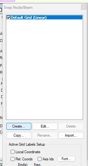
You have three types of Snap Node/Beam or Plate to choose from (Linear; Radial; Irregular).
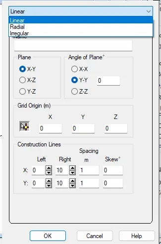
Input the values and click on Ok, the generated grid will be added to the snap node/beam data sheet.
Now specify the nodes for the geometry, add beams and plates.
Using Run Structure Wizard: It is the library of most commonly used structural shape templates which the program comes equipped with. These template models can be extracted and modified parametrically to arrive at our geometry.
We can start structure wizard at the time of creating a new project.
Go to geometry menu, select Run Structure Wizard.
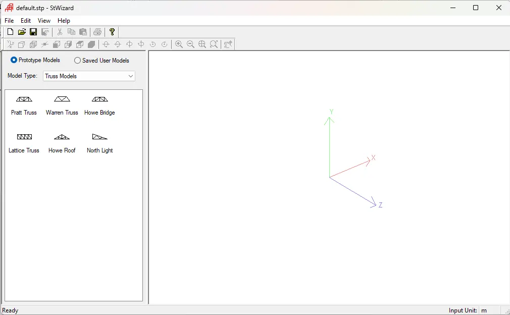
In structure wizard we can select from various structural templates available in the model Type drop down menu.
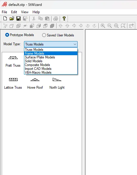
The type of structural templates available in the model type drop down menu are Truss models, Frame models. Surface/Plate models. Composite models and Import CAD models.
Choose Frame model from the list.
The following structures are available in the frame model:
Bay Frame
Grid Frame
FLOOR GRID
Continuous beam
Cylindrical frame
Reverse cylindrical frame
Circular beam
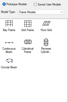
Double click on the desired structure. Select parameters dialog box will appear. This dialog box will show different type of parameters for each structure.
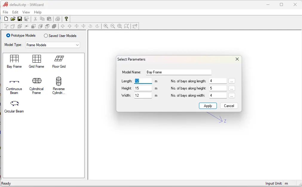
Enter the data and click on Apply.
Click on Transfer model icon from the toolbar. The confirmation message will be shown to confirm the user wants to transfer the model created in structure wizard to STAAD pro window.
Click on Yes, now STAAD Pro will ask the user to specify the pasting point in the XYZ space.
Result: The two ways in which a structural framework/model can be crated in STAAD Pro software are explained.
3.3 Elaborate the different support conditions in STAAD Pro.
Aim: To explain about the different support conditions in STAAD Pro.
Procedure:
STAAD Pro provides several types of supports to model any structural case. Supports are essential part of the input file. Without this part, the Analysis may not run, and may produce an error message.
Different support conditions available in STAAD Pro are:
Fixed support
Fixed but support
Pinned support
Enforced support
Enforced but support
Fixed Support: Fixed in STAAD Pro means there will be no movement in any direction, and no rotation around any axes. There will be six reactions on this support: Fx, Fy, Fz, Mx, My, and Mz. Used mostly to model isolated footings. Can be used with Staad Foundation etc to design the footing after the analysis results generated from STAAD Pro.
Pinned Support: Pinned in STAAD Pro means there will be no movement in any direction but there will be rotation around all axes. There will be three reactions only on this support: Fx, Fy, Fz. Used mostly in plane structure. If used in plane structure, there will be only two reactions Fx and Fy (which is axial and shear respectively) as Fz will not be considered by the structure itself.
Enforced But support: This support is used in cases of releasing your fixed support, especially in 3D frames. User can control which of the three forces, or the three moments to be released. This will give the user the power to model the structural case exactly. You can release any of the following: Fx, Fy, Fz, Mx, My, Mz.
Results: Different support conditions available in STAAD Pro are explained.
3.4 How will you extract the stress distribution for a staircase slab?
Aim: To extract the stress distribution for a staircase slab.
Procedure:
Create nodes for staircase.
Assign the plate element by connecting the nodes.
Define load cases and load combinations to the plates created.
Create mesh on the plate element.
Click on Run analysis or press Ctrl + F5.
Go to post processing mode, click on plate result option.
Drop down the list, click on stress distribution result option.
Choose the stress type. Click on OK.
The stress distribution result will be displayed in different colours on the element.
Result: The process of extracting the stress distribution for a staircase slab is explained.
3.5 Explain the different ways to view SFD and BMD in STAAD Pro.
Aim: To know about different ways to view SFD and BMD in STAAD Pro.
Procedure:
To view bending moment and shear force diagrams in STAAD, you need to first create a model, define the material properties, assign the loads and supports, and run the analysis. Then, you can select the member you want to view, and click on post processing tab. Under the Results menu, choose beam diagrams, and select the type of diagram you want to see: Bending Moment, Shear Force, Axial Force, or Torsion.
Double click on the beam after the analysis. Click on shear, bending and deflection option to view the results.
Result: The process to view SFD and BMD in STAAD Pro is explained.
PRACTICAL
Analyze the following structural elements and validate the results.
A. Simply Supported Beam
a. A Simply supported beam with two point loads symmetrically placed
b. Span L = 20 m
c. Load P = 50 kN each
d. Both P located at 5 m from each support
B. Fixed Beam
a. Span L = 16 m
b. Uniformly Distributed Load w = 9 kN/m
Aim: To analyze the following structural elements
a) Simply Supported Beam:
A Simply supported beam with two point loads symmetrically placed
Span L = 20 m
Load P = 50 kN each
Both P located at 5 m from each support
b) Fixed Beam:
Span L = 16 m
Uniformly Distributed Load w = 9 kN/m
Procedure:
a. Simply Supported Beam:
Open STAAD Pro software.
Create a new project.
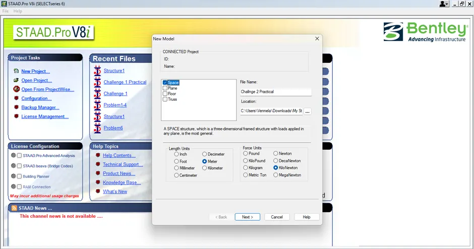
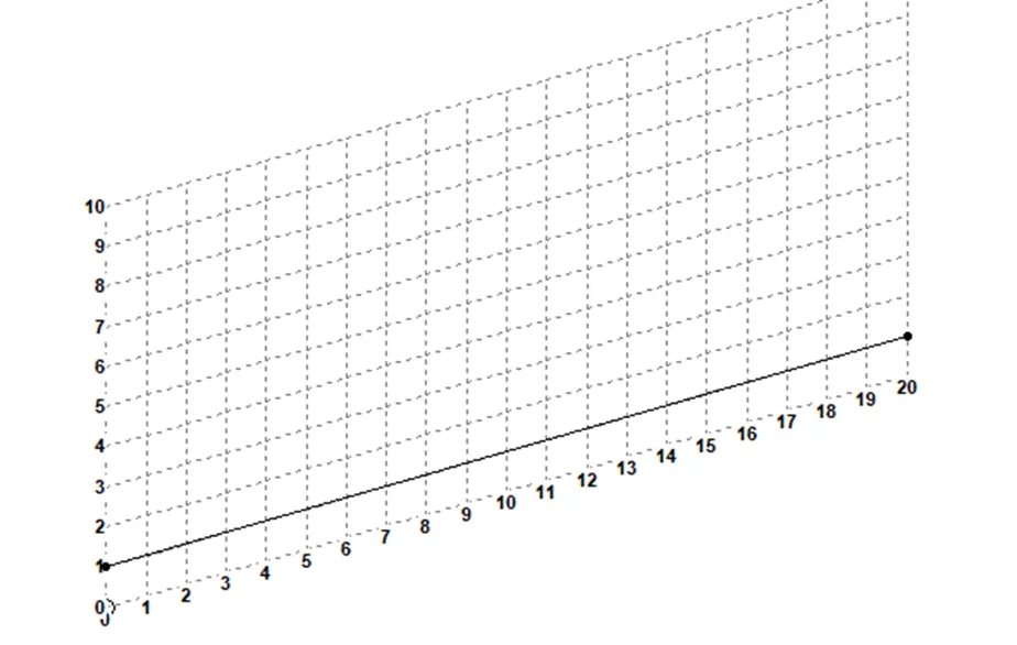
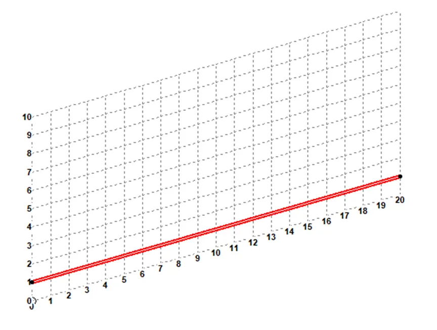
Create a beam of length 20 m by placing nodes.
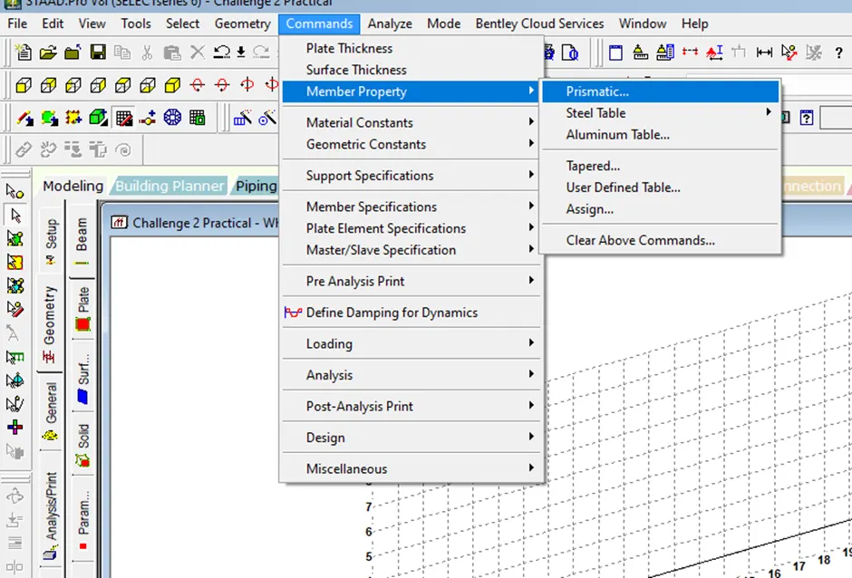
Go to commands > member property> Prismatic.
Choose Rectangle, input the depth and width value. Select the material.
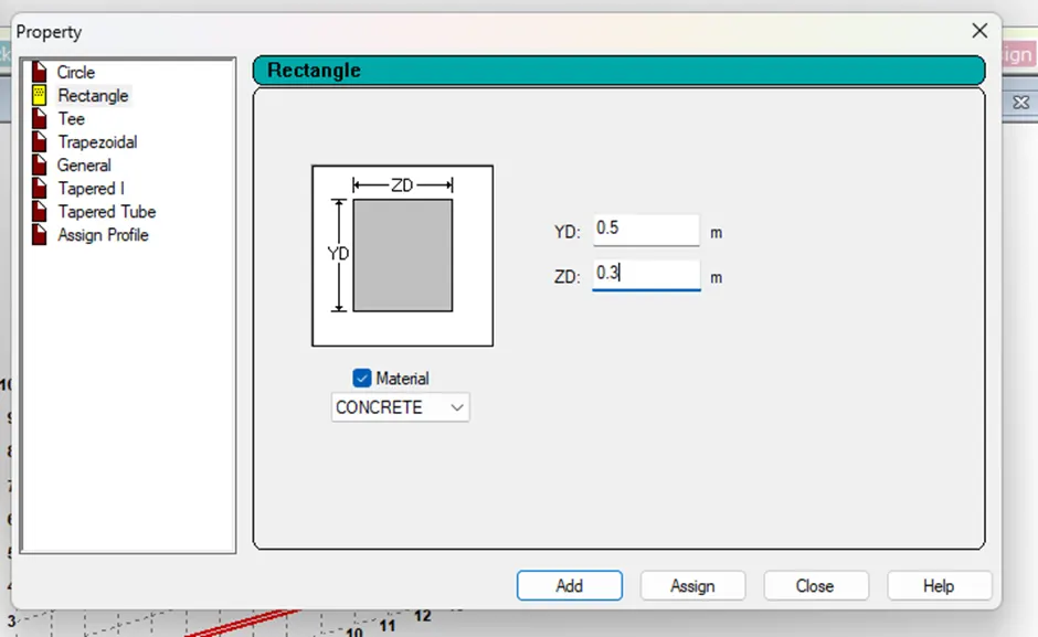
Click on add and close.
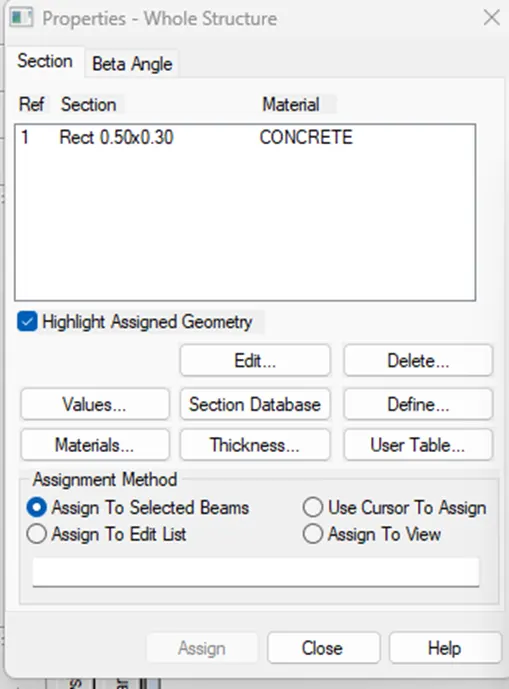
Select the section in properties, choose any assignment method, click on assign and close.
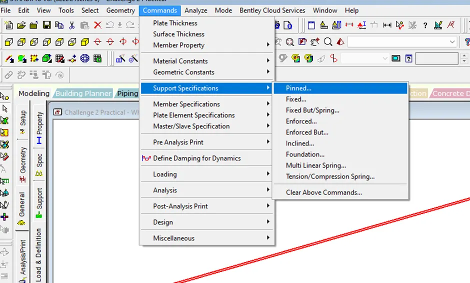
Go to commands> support specifications> pinned.
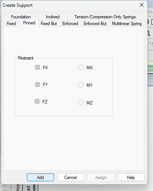
Click on Add.
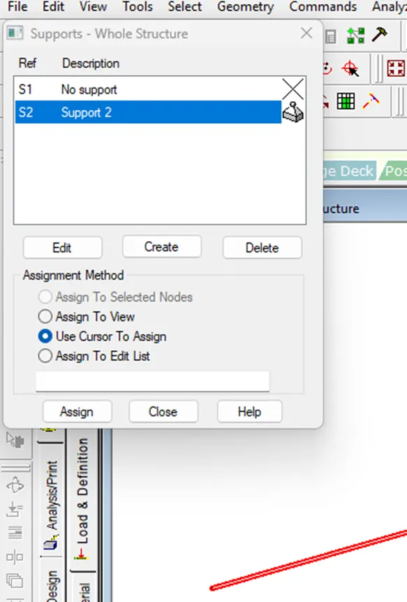
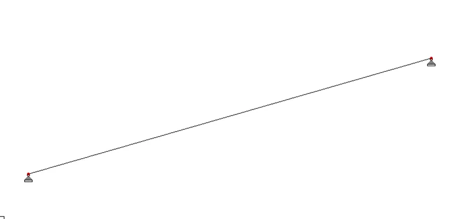
Select the support created and choose any assignment method, select the nodes, click on assign and close.
Go to commands> Loading> Primary load.
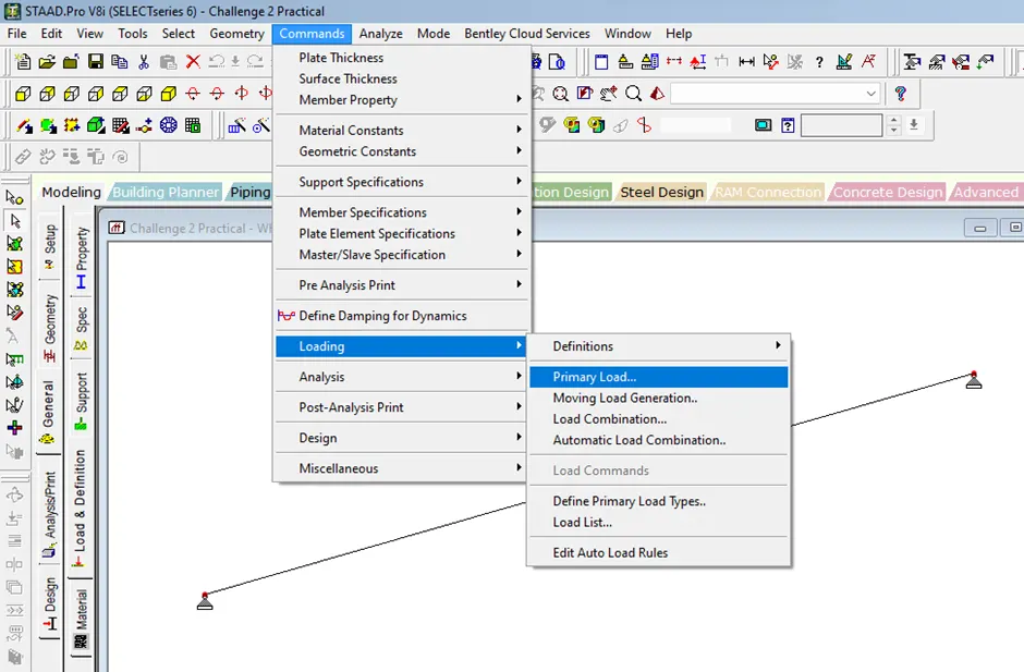
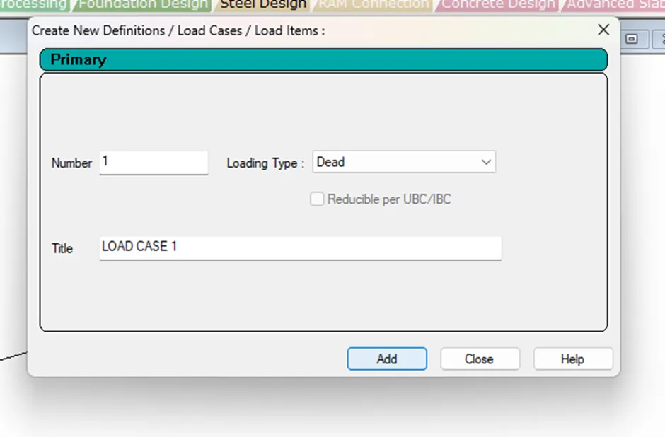
Select loading type, add title, click on add and close.
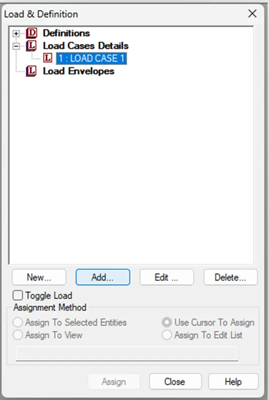
Click on load case 1 in Load & Definition dialog box and click on Add.
Go to member load> concentrated force.
Input the load value and the first load distance from the support.
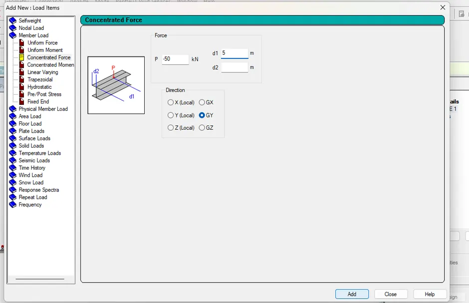
Click on add.
Again, input the load value and second load distance from the support.
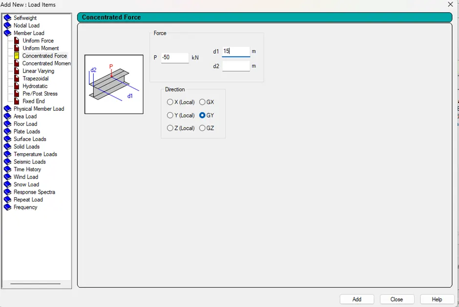
Click on Add and close.
Select the created load from load case details, choose any assignment method and click on assign.
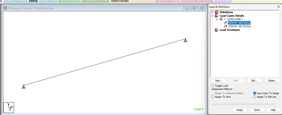
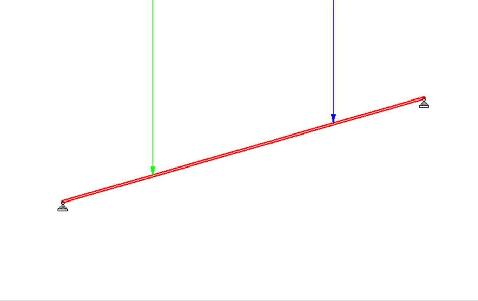
Two loads of 50kN are applied on the beam of 20 m span.
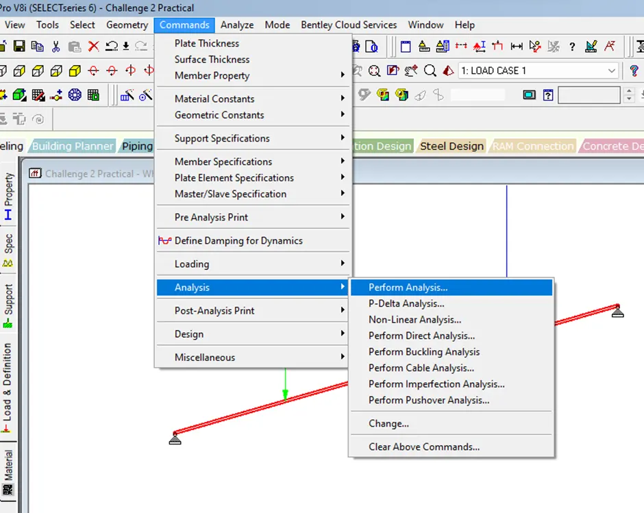
Go to commands> analysis> perform analysis.
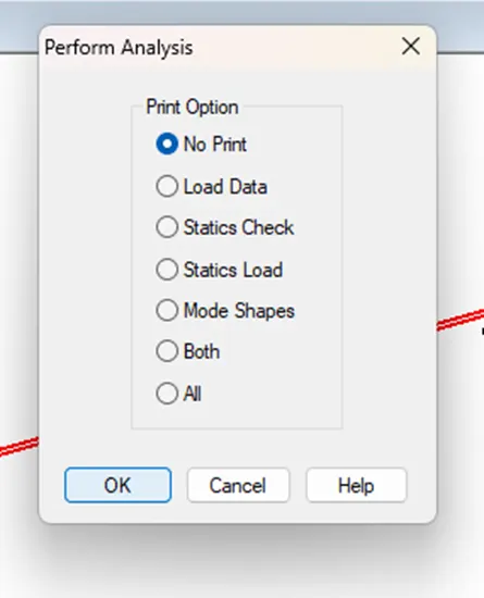
Click on OK.
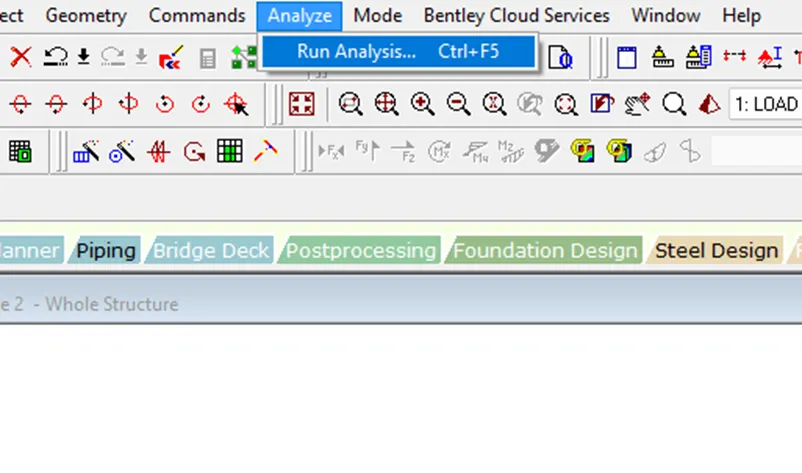
Go to analyze tab and click on Run analysis.
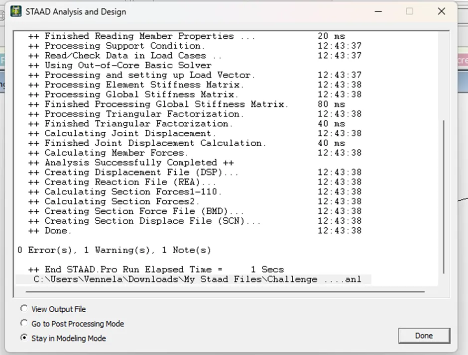
Select post processing mode and click on done.
Go to results menu and select the required result.
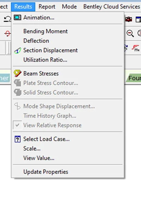
Click on the icon in the results to view the result.

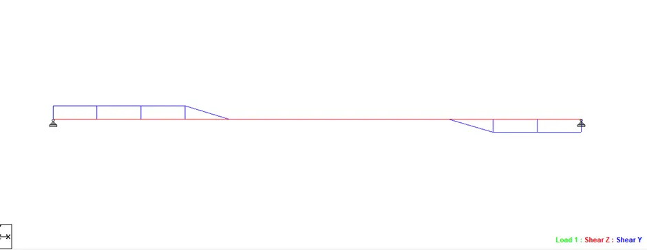
Shear Force Diagram:
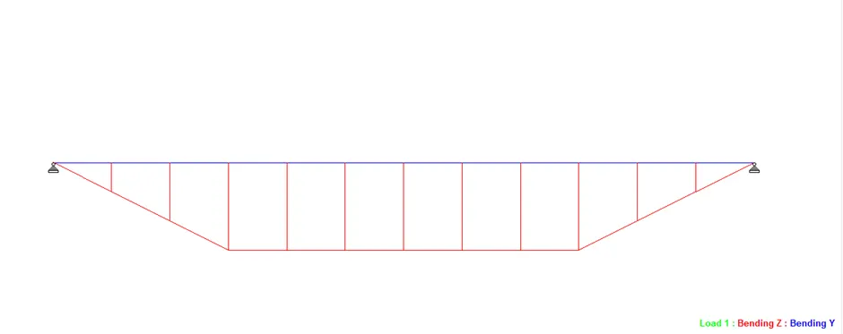
Bending Moment Diagram:
b. Fixed Beam:
Open STAAD Pro software.
Create a new project.
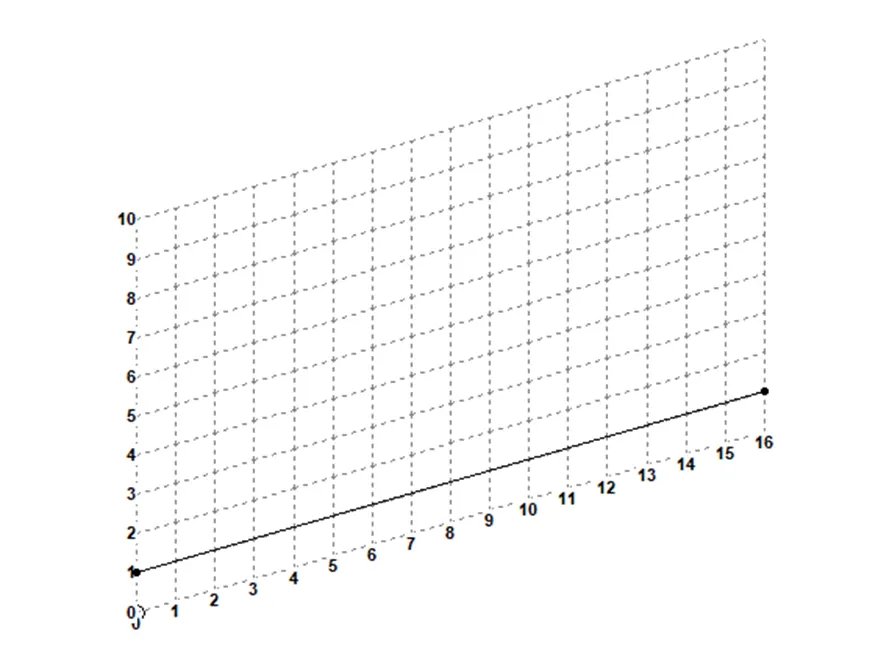
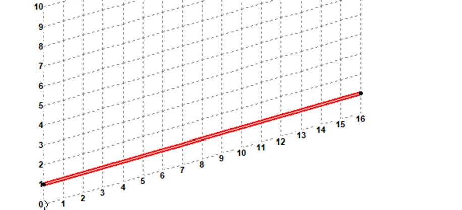
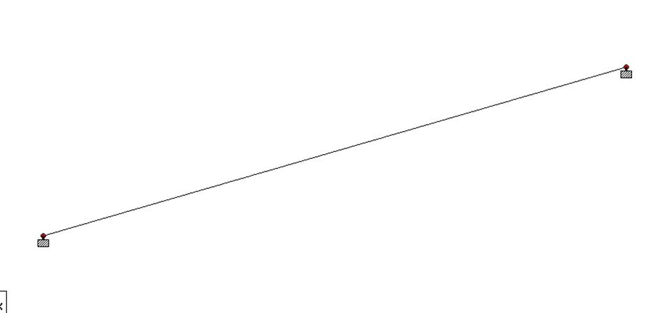
Create a beam of length 16 m by placing nodes.
Go to commands > member property> Prismatic.
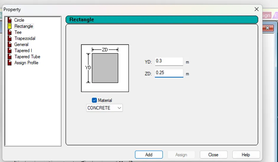
Choose Rectangle, input the depth and width value. Select the material.
Click on add and close.
Select the section in properties, choose any assignment method, click on assign and close.
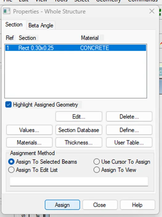
Go to commands> support specifications> fixed.
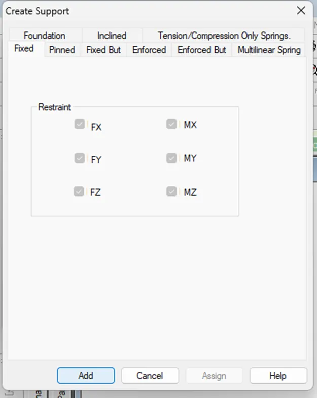
Click on add.
Select the support created and choose any assignment method, select the nodes, click on assign and close.
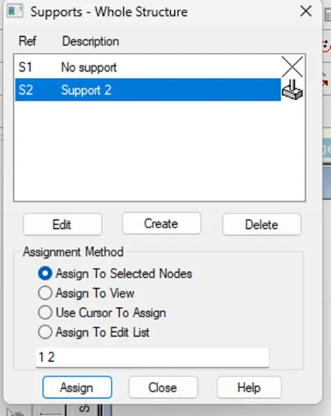
Go to commands> Loading> Primary load.
Select loading type, add title, click on add and close.
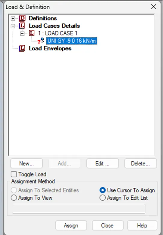
Click on load case 1 in Load & Definition dialog box and click on Add.
Go to member load> uniform force.
Input the load value and the first load distance from the support.
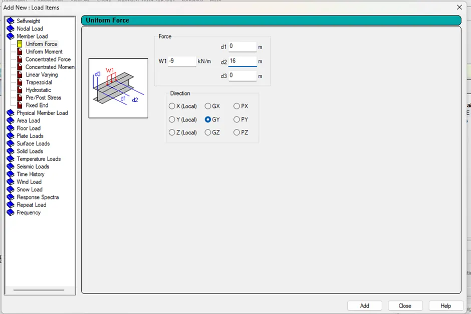
Click on Add and close.
Select the created load from load case details, choose any assignment method and click on assign.
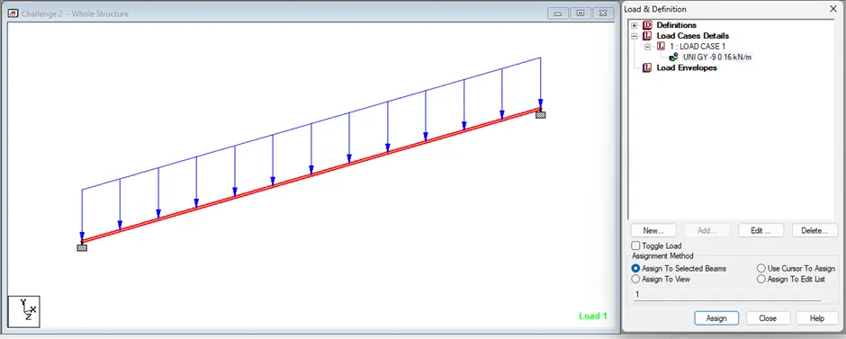
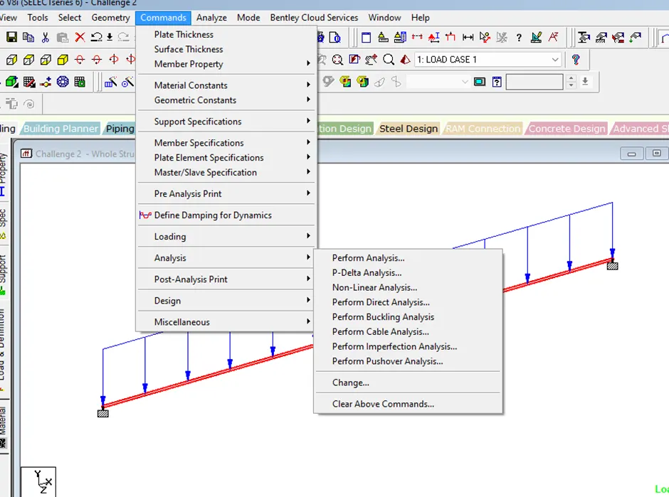
Go to commands> analysis> perform analysis.
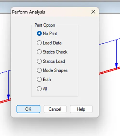
Click on OK.
Go to analyze tab and click on Run analysis.
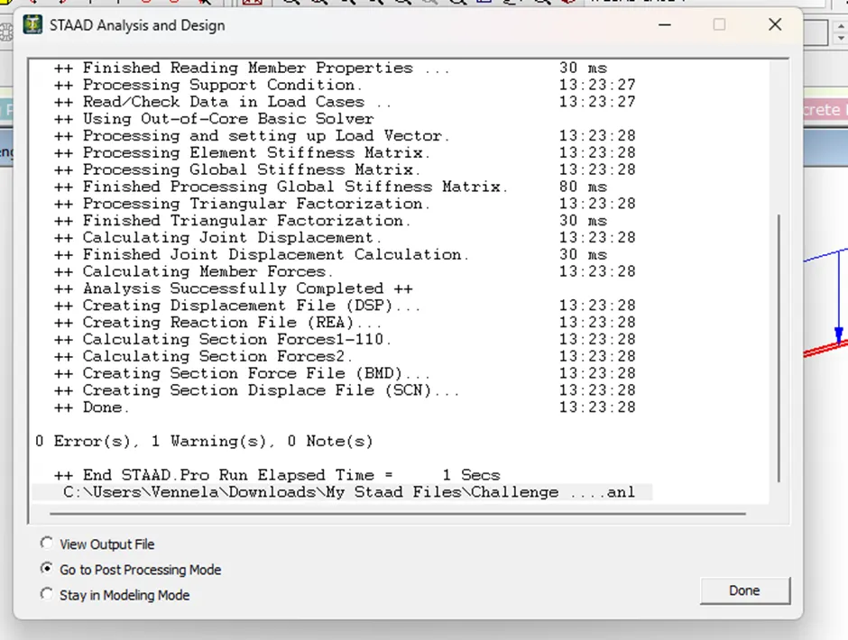
Select post processing mode and click on done.
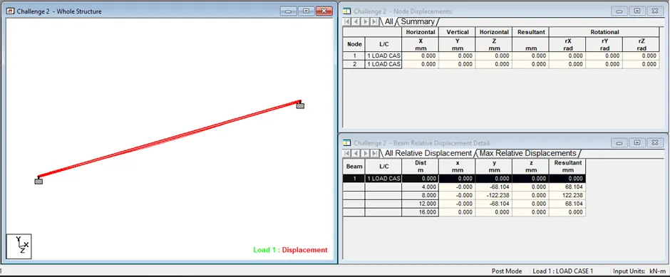
Go to results menu and select the required result.
Click on the icon in the results to view the result.
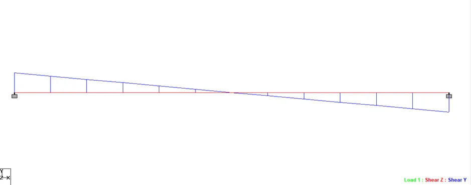
Shear Force Diagram:
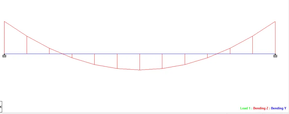
Bending Moment Diagram:
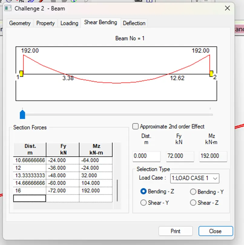
Result: Simply supported and fixed beams are analyzed and results are obtained.