Week 2:- BiW Fixture Basics Challenge
What is the process of project execution activity?
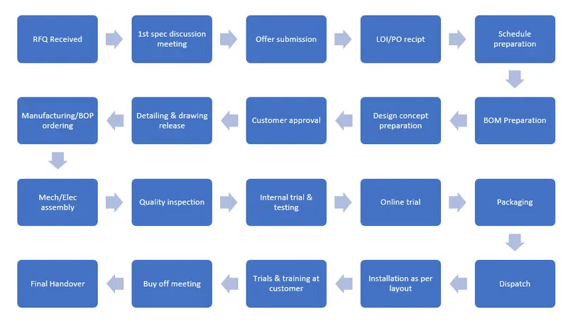
- RFQ (Request for Quotation): RFQ is request for quotation where in a customer gives his requirements, specifications, etc in form of document or data to study or work on it and give the commercial offer, technical offer, timeline of the project to the customer.
- 1st Spec discussion meeting: After RFQ is received from customer, technical offer, commercial offer, timeline of the project, etc., will be discussed and prepared. In this time required for Data study,3D design concept, simulation validation, quality check, 2d drawing release, bought outs, manufacturing, assembly, installation & commissioning will be discussed and prepared in the technical offer. Based on technical offer, commercial offer will be finalized.
- Offer submission: After the finalization in the meeting, the offers will be submitted to customer. Customer will also get offer from other suppliers. Based on the Technical, cost, quality, standard and name in the industries the customer will finalize the offer.
- LOI/PO receipt: After offer has been finalized customer will release the LOI/PO purchase order. Once PO is released, we have to start the work and have to prepare the schedule.
- Schedule preparation: Schedule preparation is dividing the different activities like kick off meeting, design data study, DAP, simulate, Quality Check, 2D detailing, drawing check, release of BOM, Manufacturing Bought outs of electrical & mechanical components, Assembly of Fixture, paint, trial run out, installation etc. These activities will be traced in the schedule preparation chart.
- BOM preparation: Bill of materials like cylinders, motors, etc which is required for the project are prepared.
- Design concept preparation: The concept preparation would include the process like load act on panels, clamping process, spot to be welded first, travel of the gun. In this concept preparation we should conceptualize the basic data like spot plan, cycle time etc. In design concept preparation, the design of the layout is been prepared at very initial level which gives the information of placements of robots and fixtures.
- Customer approval: After design concept preparation the customer will review the design concepts. If some correction is needed to be done in concept design it will be discussed and after meeting the requirement of customer, they will give approval to the design to go on with further activities.
- Detailing & drawing release: Once the customer approves the process, the detailing of the fixture parts which is to be manufactured should be done with giving appropriate dimensions and GD&T symbols.
- Manufacturing/BOP ordering: Once detailing is done the drawings will be released to manufacturing department where they will start manufacturing of all items like risers, mylars and will place the order for cylinders, sensors as per the specification.
- Mech/Elec assembly: After the materials ordered are received. The QC department will check the working conditions and technical specification. After the quality check the mechanical & the electrical parts are assembled as per design.
- Quality inspection: After the assembly the QC people will again inspect if the assembly is according to the design. CMM inspection is done to check relative dimension between two pins and resting. All dimensions, positional accuracy coordinates are checked using CMM.
- Internal trial & testing: In internal trial and testing we will see by putting the assembly in the fixture whether the seating of assembly/panel is getting placed correctly, whether the clamping operation are done properly also whether the pins are getting into the holes.
- Online trial: Online trail will be done in automatic mode through control panel. Everything should work through electrical connection are per the sequence and process is defined.
- Packaging: After the trials taken and approval from QC, packaging is done to avoid damage in fixtures while transportation which may also lead to affect the function of fixture.
- Dispatch: After the fixture is been packed for delivery it’s been dispatched to the customer.
- Installation as per layout: According to the design of the layout prepared initially which gives the information of placements of robots and fixtures the installation & commissioning team will install the fixtures.
- Trials & training at customer: Production trials will be taken at customer end. During technical offer we will be confirmed that n-number of assemblies will be produced within 8hrs/12hrs shifts. So, in customer trial we have to achieve the confirmed quantity of assemblies. Once it is achieved training will be given to the operator, staffs, engineers who will be involved in this process. The sequence of working process by the fixture will be explained in detail.
- Buy off meeting: In this meeting customer will give reviews about the fixtures, and if customer needs any additional modifications to be made, it will be discussed and finalize in the meeting for customer satisfaction.
- Final handover: After completing all the stages the fixtures are handed over to the customer.
What are the types of joining processes?
The durability and performance of any structure is largely dependent on the quality and design of component joints. Whole component cannot be made into one piece.
The two types of joining proccess are:
- Metallurgical Joining: In Metallurgical joining process the work piece is deformed by applying current through pressure or through an electrode. It includes process like welding, brazing, soldering, etc
- Mechanical Joining: In mechanical joining process the sheets are joined using fastners, rivets. It includes process like mechanical fastening,self piercing riveting,hemming,seaming,shrink fitting,etc
-
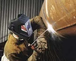
Welding: Welding is process of joining similar metals by the application of heat.Welding can be obtained with or without application of pressure and with or without addition of filler metal, which is known as electrode.During welding, the edges of these metal pieces are either melted or brought to plastic condition. The welding process is used for making permanent joints, which is obtained by homogeneous mixture of two materials. The differnet types of welding are arc welding,spot welding,TIG welding,MIG welding,gas welding,diffusion welding,etc
-
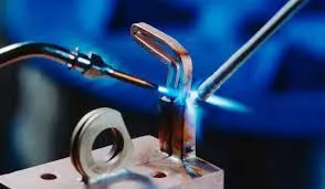
Brazing: Brazing is a metal-joining process in which two or more metal items are joined together by melting and flowing a filler metal into the joint, the filler metal having a lower melting point than the adjoining metal.The filler metal is brought slightly above its melting temperature while protected by a suitable atmosphere, usually a flux. It then flows over the base metal and is then cooled to join the work pieces together.
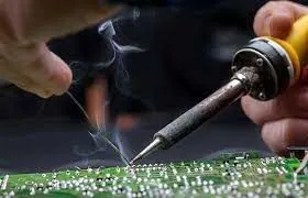
- Soldering: Soldering is a process in which two or more items are joined together by melting and putting a filler metal (solder) into the joint, the filler metal having a lower melting point than the adjoining metal.
- Mechanical Fastening: Fasterns such as nuts,bolts,screws,allen bolts,etc are used for joining two panels together.
-
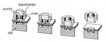
Self Piercing Riveting: It is a high speed mechanical fastening process for point joining sheet material, typically steels & aluminium alloys.It is a single step technique generally using a semitubular rivet to clinch the sheets in a mechanical joint.
-
Hemming & seaming process: Hemming & seaming are two similar metal working process in which a sheet metal edge is rolled over onto itself. Hemming is a process in which the edge is rolled flush to itself, while a seam joins the edges of two materials.
What is Resistance Welding & its application in the automotive sector?
Resistance welding is a welding technology widely used in manufacturing industry for joining metal sheets and components. The weld is made by conducting a strong current through the metal combination to heat up and finally melt the metal at localized points predetermined by the design of the electrodes and the workpiece to be welded. A force is always applied before,during and after the application of current to confine the contact area at the weld interfaces and in some application to forge the workpiece.
The types of resistance welding are:
Resistance spot welding:
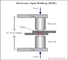
- This process is used for joining sheet material and uses shaped copper-chromium or zirconium alloy electrodes to apply pressure and convy the electrical current through the workpieces.
- Heat is developed mainly at the interface between two sheets eventullay causing the material being welded to melt, forming a molten pool, the weld nugget.
- The molten pool is contained by the pressure applied by the electrode tip and the surrounding solid metal.
Application:
- Used for joining automative BIW parts,reinforcement structures,frames,etc
- Effective in joining thinner materials with high production rate
Resistance seam welding:
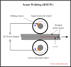
- Seam welding is a resistance welding process for joining metal sheets in continuous, often leak tight, seam joints by directly applying opposing forces with electrodes consisting of rotary wheels.
- The current and the heat generation are localized by the peripheral shapes of the electrode wheels.
Application:
- Seam welding is mostly applied in manufacturing of containers, radiators and heat exchangers etc.
Resistance projection welding:
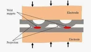
- Projection welding is a resistance welding process for joining metal components or sheets with embossments by directly applying opposing forces with electrodes specially designed to fit the shapes of the workpieces.
- The current and the heat generation are localized by the shape of the workpieces either with their natural shape or with specially designed projection. Large deformation or collapse will occur in the projection part of the workpieces implying high
Application:
- Used for mechanical fixing of autobody structures eg. Weld nuts
What is fusion welding & types of fusion welding with its application in the automotive sector?
Fusion Welding is a type of welding where joining is achieved through heat by fusing the two materials through an electrode. External application of pressure is not required.
The types of fusion welding process are:
- Arc Welding
- Resistance Welding
- Gas Welding
- High Energy Welding
Arc Welding:
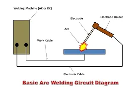
- Arc Welding process involves either consumable electrodes or non consumable electrodes.
- Arc is produced between the tip of electrode and workpiece by use of AC or DC Power
Types of Arc Welding:
- Manual metal arc welding
- Gas-shielded metal arc welding (Metal inert gas (MIG) welding)
- Gas-shielded tungsten arc welding (Tungsten inert gas (TIG) welding)
- Submerged arc welding
- Plasma arc welding
Manual metal arc welding:
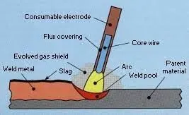
- Manual metal arc welding (MMA or MMAW) also known as Shielded metal arc welding(SMAW), or informally as stick welding.
- Stick welding is a process where the arc is struck between the metal rod (electrode flux coated) and the work piece, both the rod and work piece surface melt to create a weld.
Gas-shielded metal arc welding (Metal inert gas (MIG) welding):
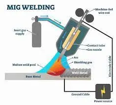
- Metal Inert Gas (MIG) Welding is an arc welding technique in which a consumable electrode is used to weld two or more work pieces.
- MIG Welding makes use of the following components:
- Consumable Electrode
- Inert Gas Supply
- Welding Head
- A.C or D.C Power Supply
Gas-shielded tungsten arc welding (Tungsten inert gas (TIG) welding):
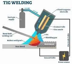
- Tungsten Inert Gas Welding (TIG Welding), also known as Gas Tungsten Arc Welding (GTAW), is an arc welding method that uses a non-consumable tungsten electrode to weld two or more workpieces. It is very much similar to Metal Inert Gas (MIG) Welding.
- The following components are necessary to perform Tungsten Inert Gas Welding:
- Power supply
- Inert Gas Supply
- Welding Head
- Filler rod
- Non-consumable tungsten electrode
Application:
- Widely used in automobile industry for joining two components
- Used for sheet metal welding
- Used for manufacturing of pressure vessel
What is the 3-2-1 principle?
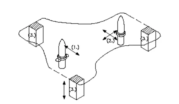
- The best and most cost effective method of part location is referred to as the 3-2-1 method.
- A workpiece in free space has 12 degrees of freedom
- 6 Translational ( positive and negative directions of X,Y,Z axes)
- 6 Rotational ( Clockwise and Anticlockwise with respect to X,Y,Z)
- So the 321 principle is applied to constrain the motions of the workpiece by suitable holding devices during various operations.
- According to 3-2-1 principle:-
- (3.)Minimum three locator blocks are used to establish part plane. Three locators, or supports, are placed under the work piece. The three locators are usually positioned on the primary locating surface. This restricts one axial movement downward, and 4 radial movements. Together, the three locators restrict five degrees of freedom.
- (2.)Round locating pin in a round hole that defines location in four directions (4-way) perpendicular to the plane Previously established. This restricts four axial movement.
- (1.)Round locating pin in a slot that defines two of the directions of the other pin (2-way).This restricts two axial movements
- Thus in this way the 12 degrees of freedom of a workpiece can be restricted using the 3-2-1 principle.
Define Body coordinate system?
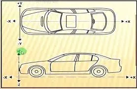
- The body cordinate system has been widely used in the automotive industry for drawing of body parts,product and process design.
- A coordinate system is a reference system consisting of a set of points,lines and surfaces used to define the position of points in space in either two or three dimensions.
- In general BCS is also called as car line and body line
- X=Longitudinal direction (Front O Line - FOL)
- Y=Transverse direction (Centre O Line - COL)
- Z=Vertical direction (Bottom O Line - BOL)
- The origin of body coordinate system (OX) is defined as the front centre of the vehicle, it indicates the length of car and the coordinate system (OZ) is below its underbody indicates height of car, and the coordinate system (OY) its starting point is the centre of car body indicates width of car.
Elaborate Body plane system & its essentials.
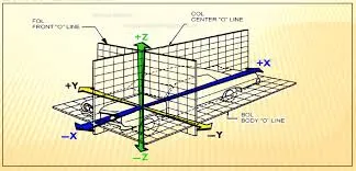
- Body planes are the reference planes in an automotive car. These planes are used to define the GD & T of all car parts in a automotive domain.
- Body planes are 3 mutually perpendicular imaginary planes. These are generally considered to be present at the Driver position or sometimes at the engine location or at the front end of the car, depending on the customer
- The Measurements from the body planes to the parts are called as bodyline dimensions
- These body planes are called as
- FOL Front “O” Line
- COL Centre “O” Line
- BOL Body “O” Line
- The Measurement along FOL or X axis is called as F/A Front Aft
- The Measurement along COL or Y axis is called as C/C Cross Car
- The Measurement along BOL or Z axis is called as U/D UP Down
Bodyline dimensions are essential because:
- It defines the exact position of each product in the vehicle w.r.t. a fixed origin
- It ensures flawless design for assembly
- While designing lines, all the designs are carried out relative to the bodyline, fixtures, turn tables, etc .,
- It assists in easy location of different parts in a vehicle
- It aims in creating a standardized system
- It assists in Quality Checks