Week 2:- BiW Fixture Basics Challenge
1. What is the process of Project execution activity?
Following flow chart shows the various processes involved in project execution activity.
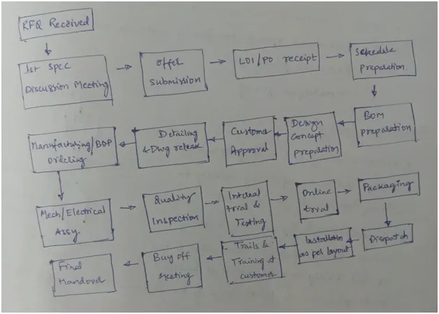
RFQ received
RFQ means Request for Quotation. It is the first step in the project execution activity. The customer specifies all details regarding project. Details include Product based details and Project based details. Commercial and Technical details of the product will be specified. Requirements and processes in the product development will be specified. Also timeline for the completion of the project is specified. All the necessary details will be specified in a document by the customer.
1st Spec discussion meeting
After receiving the RFQ, the actual project execution activity will starts in the organization. The commercial and technical details specified by the customer will be studied. The timeline for project execution will be prepared. Project design, simulation and installation details will be given utmost priority in the discussion meeting. A project report containing all the necessary details regarding execution and installation of the project will be prepared.
Offer submission
The project report prepared in the discussion meeting will be given to the customer. The customer will work on it and he will check whether the requirements are met or not. The time table prepared and project execution process is feasible or not is studied by the customer.
LOI/PO receipt
In this stage the customer will conduct an evaluation process to select the best. Customer may get similar project reports from other firms as well to select the best. Once the customer selected the best offer, the final Purchase Order will be generated and work will be started. Meanwhile, the project team in the industry also does some little work related to project so that they would adhere to the timeline of the project. Their work may include concept generation study, financial feasibility study, forecasting etc.
Schedule preparation
After the Purchase order is released, the formal work on project begins in the industry. A detailed study on project will be carried out and a timeline for project completion will be set by the project team.
BOM Preparation
In this stage, a bill of material is generated. This includes the all the necessary inputs required for timely execution of the project. Processes such as inventory management, material transportation, human capital required etc to ensure timely availability of inputs will be given utmost priority.
Design Concept generation
In this stage, various design concepts that meets the customer requirements will be generated. For example consider hood design for a passenger car. Design concept generation stage includes generation of various sketches, developing them into 3D CAD data, studying technical and commercial feasibility etc.
Customer approval
Once design concept generation process is completed, all the details will be sent customer for his approval. If it satisfies the commercial requirements then customer will approve the design concept. The customer may specify any changes if required.
Detailing and drawing release
Once the final approval is given by the customer after making the required changes, the design drawings are released with all the necessary details like dimensions and tolerances.
Manufacturing/BOP ordering
The released drawings are submitted to the manufacturing team and they start manufacturing the parts like risers, mylars etc. Then parts like motors, actuators, cylinders and sensors will be ordered.
Mechanical/Electrical Assembly
The ordered parts undergo prior quality checks and also they are checked for the required specifications. Once the quality check is done, all the parts both mechanical and electrical are assembled together and sent for the further processes.
Quality inspection
Once the components are assembled they will be sent to quality checking department. This team will perform a thorough quality inspection involving study of dimensional accuracy. CMM is used for this purpose.
Internal trial and testing
After completion of quality inspection internal trials and testing are done. The assembly is put into the fixture and checked for the positions of the pins and whether the clamping is proper or not. Operations like welding, loading and unloading are done to check the product rigidity.
Online trial
The manufacturing/assembly process will be thoroughly evaluated in automated mode. And checked whether the sequence of operations is proper or not. The product made in online trial will be sent to the customer for his approval.
Packaging and dispatch
After getting customer approval, the team will send the fixture parts for installation. The fixture is packed and proper packaging is ensured such that there is no damage to the fixture parts both dimensionally and aesthetically. After packaging is done, fixture will be dispatched to the customer.
Installation as per layout
At industrial layout will be developed in the early stages of project development that show the positions of various fixtures like robots. This layout will be designed as per functional requirements of the customer.
Trails and training at customer
After installation there will be a trial at customer place. Production trial is carried out to check the functionality of the fixtures. Then training is given to the engineers and operators at customer’s place.
Buy off meeting and final handover
In buy off meeting customer may give additional feedbacks. The customer will check the product and once he is satisfied with the operations, the fixture assembly is finally given to the customer.
2. What are the types of joining processes?
The durability and performance of any structure is largely dependent on the quality and the design of component joints. Joining comprises a large number of processes used to assemble individual parts into a larger or more complex assembly. Mechanical joining includes bolting, riveting, caulking, shrink fitting, and folding, all of which join work pieces by using mechanical energy. Metallurgical joining includes fusion welding, pressure welding and brazing/soldering which use different energies. So in general Joining processes are classified as
- Mechanical joining – Bolting, Riveting, Caulking, Shrink fitting, and Hemming
- Metallurgical joining - Welding, Pressure welding, Brazing, Soldering, Chemical joining
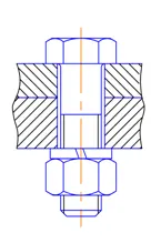
Bolting: Bolted joints are one of the most common elements in construction and machine design. They consist of fasteners that capture and join other parts, and are secured with the mating of screw threads. Image below shows bolting
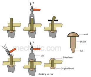
Riveting is another of the most commonly used processes for permanently joining two or more metal parts. The rivet consists of a cylindrical tube, known as a rod, which has a head to its end that can have different shapes. These heads have a larger diameter than the rest of the rivet so that this can be inserted into a hole and can be fitted.
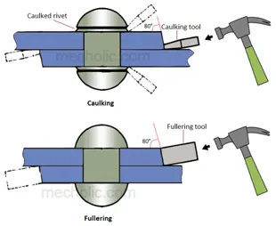
Caulking: Caulking is a process employed on riveted joints of pressure vessels like tanks, steam boiler to make joint leak proof and fluid tight. The narrow blunt chisel tool used for caulking is known as caulking tool.
Shrink fitting: Shrink fitting is a process where a size change after assembly creates an interference fit. By heating or cooling one component prior to assembly and allowing it to return to the ambient temperature after assembly, the thermal expansion creates a joint. Metals typically expand when heated and contract when cooled.
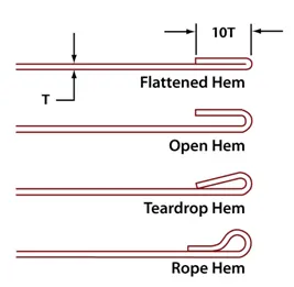
Hemming and seaming: Hemming and seaming are two similar metalworking processes in which a sheet metal edge is rolled over onto itself. Hemming is the process in which the edge is rolled flush to itself, while a seam joins the edges of two materials.
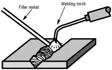
Welding: Welding joins metals by melting and fusing them together, typically with the addition of a welding filler metal. The joints produced are strong – usually as strong as the metals joined, or even stronger. To fuse the metals, we apply a concentrated heat directly to the joint area.
Pressure welding: Pressure welding uses friction or explosion to heat the joining section of metal work pieces and join them under pressure. The process is also called solid-state welding. Pressure welding is a generic term for welding methods that weld work pieces by applying mechanical pressure on the joining section (weld joint).
Brazing: Brazing is a metal-joining process in which two or more metal items are joined together by melting and flowing a filler metal into the joint, with the filler metal having a lower melting point than the adjoining metal. The filler metal flows into the gap between close-fitting parts by capillary action.
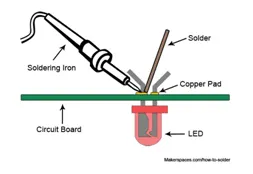
Soldering: Soldering is a joining process used to join different types of metals together by melting solder. Solder is a metal alloy usually made of tin and lead which is melted using a hot iron. The iron is heated to temperatures above 600 degrees fahrenheit which then cools to create a strong electrical bond.
Chemical welding
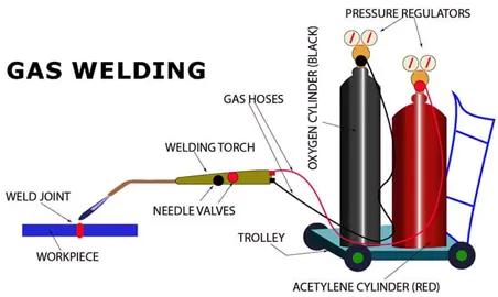
Oxyfuel: Flame contact is a very common form of welding. The most popular kind of flame contact welding is oxyfuel gas welding. Flame contact welding uses a flame exposed to the surface of the metals being welded to melt and then join them together. Oxyfuel uses oxygen as a primary ignition source in tandem with another gas such as acetylene to produce a flame which is 2500 °C at the tip and 2800-3500 °C at the tip of the inner cone.Other gasses such as propane and methanol can be used for oxyfuel welding. Acetylene is the most common gas used in oxyfuel welding.
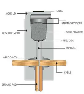
Solid reactant: Solid reactant welding uses reactions between elements and compounds. Certain compounds when mixed create an exothermic chemical reaction, meaning they give off heat. A very common reaction uses thermite, a combination of a metal oxide (rust) and aluminum. This reaction produces heat over 4000 °F. Solid reactant compounds are channeled to the two pieces of metal being joined. Once in place, a catalyst is used to start the reaction. This catalyst can be a chemical or another heat source. The heat created melts the metals being joined. Once it cools, a bond is formed. From welding together train tracks to entering bank vaults, solid reactant welding has many niche uses.
3. What is the resistance welding? Explain its application in the automotive sector?
It is a welding process where metal parts in contact are permanently joined by heating them with an electric current, melting the metal at the joint. Electric resistance welding is widely used, for example, in manufacture of steel pipe and in assembly of bodies for automobiles. The electric current can be supplied to electrodes that also apply clamping pressure, or may be induced by an external magnetic field. Image below shows resistance welding process
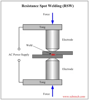
The electric resistance welding process can be further classified by the geometry of the weld and the method of applying pressure to the joint: spot welding, seam welding, flash welding, projection welding. In general, resistance welding methods are efficient and cause little pollution, but their applications are limited to relatively thin materials. Some factors influencing heat or welding temperatures are the proportions of the work pieces, the metal coating or the lack of coating, the electrode materials, electrode geometry, electrode pressing force, electrical current and length of welding time.
The advantages of the method include efficient energy use, limited work piece deformation, high production rates, easy automation, and no required filler materials.
Types
- Resistance spot welding
- Resistance seam welding
- Resistance projection welding
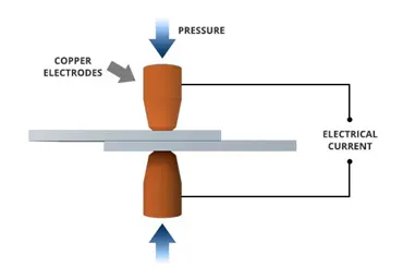
Resistance spot welding: The process is used for joining sheet materials and uses shaped copper – chromium or zirconium alloy electrodes to apply pressure and convey the electrical current through the work pieces. Heat is developed mainly at the interface between two sheets, eventually causing the material being welded to melt, forming a molten pool, the weld nugget. The molten pool is contained by the pressure applied by the electrode tip and the surrounding solid metal.
Advantages
- Short weld time and hence high weld speed.
- Highly adaptable to adaptation and robotic techniques
Typical BIW contains 5000 welds. Strength and ductility of automobile largely depends on quality of RSW.
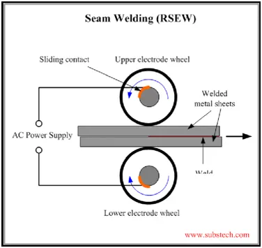
Resistance seam welding: Seam welding is a resistance welding process for joining metal sheets in continuous, often leak tight, and seam joints by directly applying opposing forces with electrodes consisting of rotary wheels. The current and the heat generation are localized by the peripheral shapes of the electrode wheels.
Seam welding is mostly used in manufacturing of containers, radiators and heat exchangers etc.
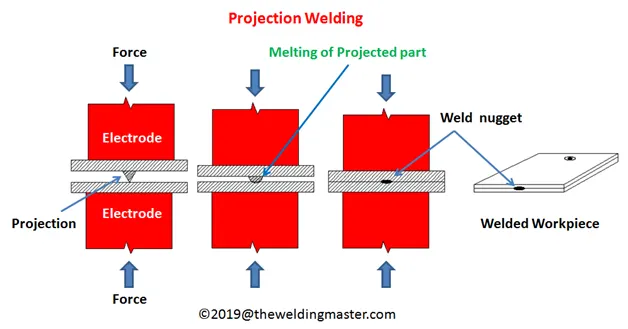
Resistance projection welding: It is a resistance welding process for joining metal components or sheets with embossments by directly applying opposing forces with electrodes specially designed to fit the shapes of the work pieces. The current and the heat generation are localized by the shape of the work pieces either with their natural shape or with specially designed projection. Large deformation or collapse will occur in the projection part of the work pieces. It is used for mechanical fixing of auto body structures, Example: Weld nuts.
Application of Resistance welding in automotive sector
Resistance spot welding (RSW) is an important process in the automotive industry. The advantages of spot welding are many: an economical process, adaptable to a wide variety of materials (including low carbon steel, coated steels, stainless steel, aluminum, nickel, titanium, and copper alloys) and thicknesses, a process with short cycle times, and overall, a relatively robust process with some tolerance to fit-up variations.
Resistance spot welding is the dominant welding process in the automotive industry. The structural integrity of a vehicle depends largely on the quality of resistance spot welds. Due to increasing demand for improved fuel efficiency, reduced CO2 emission and superior crashworthiness, significant effort is continuously being applied to develop lightweight materials with excellent strength-ductility combination. Resistance welding can be applied to both aluminum-aluminum and steel-steel joints.
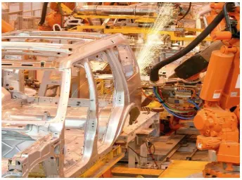
The conventional steel body of a car, on an average, contains 4500 spot weld joints. Resistance spot welding is the principle joining method used in automotive industries and has been for many years. RSW is automated and used in the form of robotic spot welding in automotive industries to weld the sheet metals to form car body. Industrial robots spot welding the car body in production line is shown in the photograph given below
What is fusion welding? Explain types of fusion welding with their application in automotive sector
Fusion welding is a generic term for welding processes that rely on melting to join materials of similar compositions and melting points. Due to the high-temperature phase transitions inherent to these processes, a heat-affected zone is created in the material. Fusion welding is used in the manufacture of many everyday items including airplanes, cars, and structures.
Types
- Electrical fusion welding – Arc welding, Laser beam welding and Induction welding
- Chemical welding – Oxy fuel welding and solid reactant welding
Arc welding
Arc welding is one of the many types of fusion welding. Arc welding joins two pieces of metal together by using an intermediate filler metal. The way this works is by completing an electrical circuit to create an electrical arc. This electrical arc is 6500 °F (3593 °C) in its center. This electrical arc is created at the tip of the filler metal. As the arc melts the metal, it is moved either by a person or a machine along the gap in the metals, creating a bond. This method is very common as it is typically done with a hand held machine. Arc welding machines are portable and can be brought onto job sites and hard to reach areas.
Types of Arc welding
- Manual metal arc welding
- Gas shielded metal arc welding
- Gas shielded tungsten arc welding
- Submerged arc welding
- Plasma arc welding
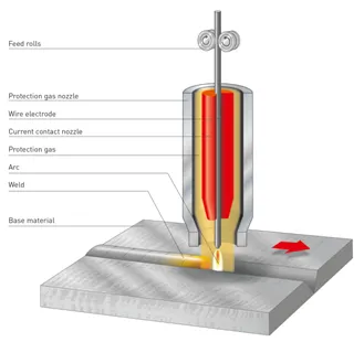
Gas shielded metal arc welding: Gas-shielded metal arc welding is an arc welding process where an endless wire electrode melts under a shielding-gas cover which protects the welding zone against environmental influences. This process is characterised by high versatility with respect to the material, the degree of mechanisation and the welding position. Gas-shielded metal arc welding can be used for almost all weldable materials.
Unalloyed and alloyed steels are preferably welded with active gases, e.g. carbon dioxide. This process variety is called metal active gas welding, in short MAG welding. High-alloyed steels and materials like aluminium, magnesium, nickel-based materials and titanium are welded with inert gases, e.g. argon. The process variety used in this case is called metal inert gas welding, in short MIG welding.
Gas-shielded metal arc welding can be used for joining thin sheets with a material thickness from 0.8 mm as well as for welding thicker sheets with a material thickness of more than 10 mm.
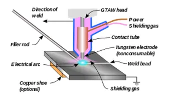
Gas shielded tungsten arc welding: Gas-shielded tungsten-arc welding is a fusion process that uses a virtually non-consumable electrode in a completely inert gas shield. The metal tungsten has the highest melting point of all metals, at 3410 °C.
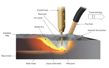
Submerged arc welding: Submerged Arc Welding (SAW) is a joining process that involves the formation of an electric arc between a continuously fed electrode and the workpiece to be welded. A blanket of powdered flux surrounds and covers the arc and, when molten, provides electrical conduction between the metal to be joined and the electrode.
Plasma arc welding: Plasma arc welding (PAW) is an arc welding process similar to gas tungsten arc welding (GTAW). The electric arc is formed between an electrode (which is usually but not always made of sintered tungsten) and the workpiece. The key difference from GTAW is that in PAW, the electrode is positioned within the body of the torch, so the plasma arc is separated from the shielding gas envelope. The plasma is then forced through a fine-bore copper nozzle which constricts the arc and the plasma exits the orifice at high velocities (approaching the speed of sound) and a temperature approaching 28,000 °C (50,000 °F) or higher.
Laser beam welding
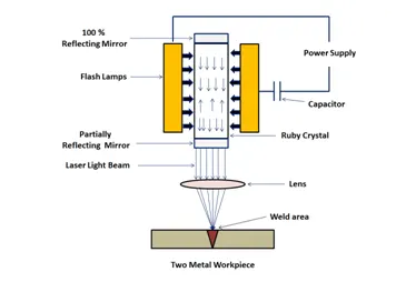
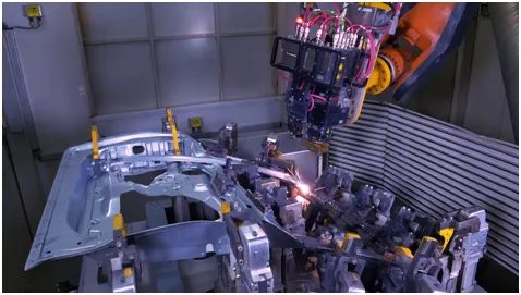
Laser beam welding (LBW) is a welding technique used to join pieces of metal or thermoplastics through the use of a laser. The beam provides a concentrated heat source, allowing for narrow, deep welds and high welding rates. The process is frequently used in high volume applications using automation, as in the automotive industry.
What is the 3-2-1 principle?
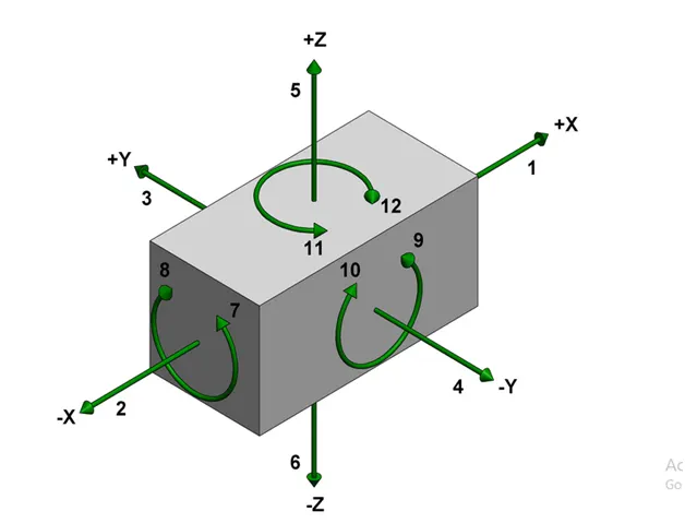
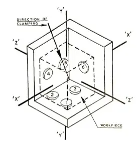
A workpiece free in space can move in an infinite number of directions. For analysis, this motion can be broken down into twelve directional movements, or "degrees of freedom." All twelve degrees of freedom must be restricted to ensure proper referencing of a workpiece.
As shown in image, the twelve degrees of freedom all relate to the central axes of the workpiece. Notice the six axial degrees of freedom and six radial degrees of freedom. The axial degrees of freedom permit straight-line movement in both directions along the three principal axes, shown as x, y, and z. The radial degrees of freedom permit rotational movement, in both clockwise and counterclockwise radial directions, around the same three axes.
The devices that restrict a workpiece's movement are the locators. The locators, therefore, must be strong enough to maintain the position of the workpiece and to resist the cutting forces. This fact also points out a crucial element in workholder design: locators, not clamps, must hold the workpiece against the cutting forces.
A widely used method of accomplishing these objectives uses the 3-2-1 principle, so-called because it entails three steps that employ three, then two, then one fixed points of known location. Since that adds up to six fixed points, it’s also known as the six point method.
In the three steps of the 3-2-1 method, three mutually perpendicular planes, called datum planes, are introduced, one at each step. These three planes define the workpiece position, and together with opposing clamping forces fully constrain the part. Let’s take a look at the details of the 3-2-1 method.
First plane
Geometry tells us that three points are required to define a plane. This is the "3" in 3-2-1. So, three specific points are used to define the first plane. Fewer than three points cannot define a plane. Different parts may rest on different combinations of three points, resulting in variation between finished parts. The part’s six degrees of freedom have now been reduced to three. It can still move along the X or Y axes, and it can still be rotated about the Z axis.
Second plane
A second plane, if it is perpendicular to the first, can be defined by two points, the "2" in 3-2-1. The part is now constrained to one degree of freedom: movement along the Y axis.
Third plane
A third plane, if it is perpendicular to both of the first two planes, can be defined by one point, the "1" in 3-2-1. The part is now entirely constrained. It cannot move along or rotate about the X, Y, or Z axes.
Define Body Coordiante system
The body coordinate system is widely used in automotive industries for drawing parts, products and process design.
A coordinate system is a reference system consisting of a set of points, lines and surfaces used to define the position of points in space in either two or three dimensions.
To represent the position of BIW car parts, welding fixtures and its unit assemblies with its individual parts in 2D drawings, their respective positions are shown with reference to (X=0, Y=0, Z=0) positions. In short, it shows in 2D XY, YZ or XZ coordinate position of BIW fixture parts or assemblies with reference to origin X=0, Y=0, Z=0.
Let us consider a situation if an individual fixture designer starts designing a part or panel on their default axes system then it will be difficult to assembly or position the part with respect to each other. So in order to avoid this all designer start designing with respect to car axes system (which is generally at the center of the front axle)
We consider a case where the axes system is from the front end of the car
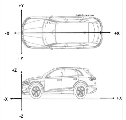
- X – Longitudinal direction [Front ‘O’ Line – FOL]
- Y – Transverse direction [Center ‘O’ Line – COL]
- Z – Vertical direction [Bottom ‘O’ Line – BOL]
The origin of the body coordinate system OX is defined at the front center of the car and it indicates the length of the car. The origin of the OZ is defined at the bottom of the car in the plane where the tire of the vehicle touches the ground and it indicates the height of the car. Finally, the origin of the OY coordinate lies in the center of the car and it indicates the width.
Elaborate body plane system and its essentials
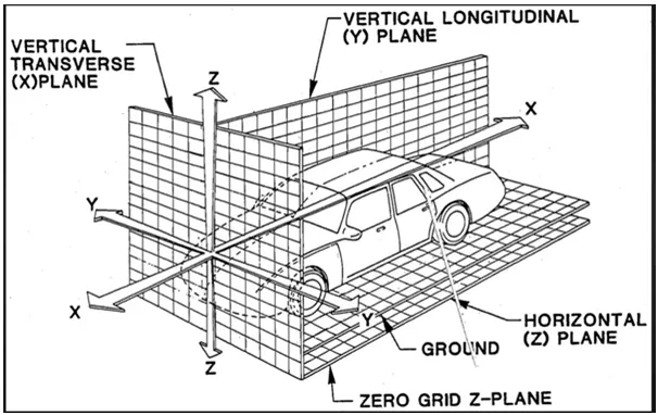
- Body planes are the reference planes in an automotive car. These planes are used to define the GD&T of all car parts in a automotive domain.
- Body planes are three mutually perpendicular imaginary planes. These are generally considered to be present at the driver position or sometimes at the engine location or at the front end of the car depending on the customer.
- The measurements from the body planes to the parts are called as bodyline dimensions
- These body planes are called as
- FOL
- COL
- BOL
- The measurement along FOL is called F/A Front Aft
- The measurement along COL is called C/C Cross Car
- The measurement along BOL is called U/DUP down
Bodyline dimensions are essential for the reasons stated below
- It defines the exact position of each product in the vehicle with respect to a fixed origin
- It ensures flawless design for assembly
- While designing guidelines all the designs are carried out relative to the body line, viz, fixtures, turn tables etc.,
- It assists in easy location of different parts in a vehicle
- It aims in creating a standardized system
- It assists in quality checks.