Week 2:- BiW Fixture Basics Challenge
1) What is process of project execution activity?
Project activities are those basically are being processed or being practiced in general project of BIW begins. Project activities are task from start to end of project. There are various step involved in project
RFQ:
In BIW fixture design project begins. It starts with basic requirement or RFQ that we receive from customer. RFQ means request for quotation where in customer give his requirement specification etc. in form of some document or data to study or to work on information include such as technical offer, commercial offer, timeline of project Based on that we have processing to execute project.
1st specification discussion meeting & offer submission:
In this the documents related technical offer, commercial offer, project execution, timeline required to complete the project are prepared. The time required to 3D design, analysis of design, drawing & detailing, manufacturing, assembly & commissioning etc. is considered. Then cost of all operation is considered. By considering these kinds of things the offer is prepared & submitted to customer
- PO/LOI: Once we submitted offer customer will study the offer at the same time he will get offer from different supplier & vendor. He compares these technical offers & based on cost whichever suit best for his requirement. Then he will release LOI or PO with its terms & conditions as stated earlier.
- Schedule Preparation: In project each activity depends on previous activity. So if previous activity has not completed on time it will cause delay in next activity date is fixed so that it will move further. Each activity has assigned specific time i.e. when activity is starting & when it is ending? So we have some back plan so that final date comes to close final delivery date. There need to be proper scheduling to be done to complete project in time. “On time delivery” is one of the major requirements from customer side also customer wants commitment must be follow in respect of time.
- BOM Preparation: BOM preparation is listing down of part list which includes bought out parts, vendor parts, and consumable items with qty. of each item. Through BOM preparation material budget will be fixed. B/O parts include motor, gear box, cylinder, pneumatic & hydraulic valves etc. Also vendor parts include all machined, fabricated parts etc. whereas consumable includes like oil, grease, glue, loctite etc. .
- Design concept preparation: Further step is to design a concept. A concept is based on all specification, received data from customer as 3D data of car panel, drawing, drawing std., design std., manufacturing std. After studying all data design concept is build.
- Customer approval: As design concept ready then it is send to customer for its approval. It is also known as design approval process (DAP) or customer approval process. In that customer will check that all his specification consider or not in specifications. Whether it is as per technical offer submitted then only he approves prepared concept. Some points will be raised by customer. These changes are updated to design team by project team. Design team again work on it some modification or changes are necessary to improve design like clamping need to be improved or this mechanism will work fine, sensor should be of this make. These changes are again updated to customer. Once he gave final approval we will move further for detailing & dwg. release.
- Detailing & Dwg. release: In detailing all assemblies broken down into its child parts. Parts of assembly are segregated into std. as well as manufactured. For std. parts own data sheet or specification sheet prepared to purchase it from catalogue. e.g. motor power, motor current rating, torque produced, shaft rpm which suit for our application. For vendor parts all detail should be provided on dwg. Like all dimension of part with tolerance, surface finish, surface treatment, hardness, welding note all should be mention on dwg. These dwgs are checked & released for manufacturing.
- Manufacturing & B/O ordering: Manufacturing department will receive all dwg to start manufacturing of items like mylar, blade, riser, base frame. Also purchase team will place order for B/O parts like motor, gearbox, cylinder & valves. As material get ready, QC team should inspect all part received is as per specification or not otherwise it will create issue later which will waste our time
- Mechanical & electrical assembly: After qc check, parts are available for assembly. A station is integration of all mechanical as well as electrical assembly. Assembly team will do all assembly as per dwg. All station are build as per layout Then again qc team should be involved for checking assembly as per final dwg., all coordinate dimension should be ok as per design data.
- Internal trial & testing: After approval of qc team, Internal trials & testing started. The first step involves putting assembly in fixture manually to check that it being fix properly, locating pin match with hole, clamping is ok, loading & unloading of part is easy. Also operating height is also checked, it is ergonomically correct. Then start taking trials on fixture for welding feasibility, gun approachability in fixture. Then go for online trial.
- Online training: After successful of trial next step is online training. In online training has two mode manual & automated. In online trial system is run through control panel. All sensor, actuator, motor current & temperature, noise, all alarm, also safety should be tested. All process must be executed as per sequence also cycle time meet. In online training system run for certain cycle & actual production taken to ensure system run successfully.
- Packaging: After trial get successful, customer give approval to dispatch system. To dispatch whole system needs to disassemble station wise & pack properly. Delicate material should be packed properly otherwise there is chance of damage aesthetically or functionally during transportation. During packaging labeling, special handling instruction should be pasted on particular parts to convey message of taking care during handling & transportation.
- Dispatch: All material transported at customer site through trucks, container, and ships or by air.
- Installations: All system is assembled & installed at customer end as per layout approved initially in DAP. All station, robots, conveyor mounted as per distance specified in layout. Robot arm should be reachable to station, pick & drop point. It shouldn’t foul with other equipment. Also some adjustment should be provided for leveling purpose at robot conveyor base, station base frame like leveling stud to align with other equipment. Layout is always specified at the time of initial design stage & it has to be approved by customer.
- Trial & training at customer end: Once installation is done trial start at customer end. So there will be production trial, online trial. Production trial is necessary because at the time of designing fixture, it also committed no. of unit that will be manufactured from that fixture also whether it is meeting quality, bench mark or not. Also in technical offer it is committed that there will be 100 units per 8hrs shift will manufactured from that fixture with weld quality. So during production trial fixture capability will be ensured. Once this goal is achieved then there will be training to operator, staff member, engineers to let them to understand how process is working?
- Buy off meeting: Once training is completed there is buy off meeting between customer & project team with discussion on if there other things need to be incorporated, anything missing that described in LOI/PO or offer submission. Then customer will raise point or sometimes customer wants modification that will lead to extra quotation, extra costing according work is done as per buy of meeting.
- Final handover: Once all points raised by customer will be closed then all will go for final handover. All data, technical manual, soft hard documents will submit to customer. These are main project activity.
2) What are types of joining processes?
The durability and performance of any structure is largely depends on quality & design of components joints. Whole structure can’t be made in one piece. Two fundamental option for joining material & components.
- Metallurgical joining
- Mechanical joining.
1. Metallurgical joining:
In welding two or more parts are heated & melted or forced together, causing the joined parts to function as one. In some welding method filler material is added to make the merging of materials easier.
a)Welding
b)Brazing
c)Soldering
d)adhisive Bonding
e)Diffusion Bonding.
2.Mechanical joining:
Mechanical joining is a process for joining parts through clamping or fastening using screws, bolts or rivets. Advantages of mechanical joining include versatility, ease of use, and the option to dismantle the product in cases where regular maintenance requires it. The ability to join dissimilar materials is another benefit. A drawback of using mechanical joining is the lack of a continuous connection between parts, because the joint is achieved through discrete points. Also, holes created for joining are vulnerable to fractures and corrosion.
a)Mechanical fastening
b)Self pierce reviting
c)Hemming & seaming process
3) What is resistance welding & its application in automotive sector?
- Resistance welding is technology widely used in manufacturing industry for joining sheet metal & component.
- The weld is made by conducting a strong current through metal combination to heat up & finally melts metal at localized points predetermined by the design of electrodes and or the work piece to be welded.
- A force is always applied before, during & after application of current to confine the contact area at weld interface & in some workpiece to forge the wokpiece. Below fig. shows resistance welding technique.
Types of resistance welding:
- a) Resistance spot welding
- b) Resistance seam welding
- c) Resistance projection welding.
a) Resistance spot welding:
Resistance spot welding widely used in BIW joining processes. The process is used for joining sheet materials & uses shaped copper chromium or zirconium alloy electrode to apply pressure & convey electrical current through the workpiece. Heat is developed mainly at interface between two sheet, eventually causing material being welded to melt, forming a molten pool & weld nugget. The molten pool is contained by the pressure applied by electrode tip & surrounding solid metal. When circuit is completed current will flow from that panel or sheet metal which will generate amount of heat that is sufficient enough to melt that will be melted & get welded together.
-
b) Resistance seam welding:
Resistance seam welding is welding process for joining metal sheets in continuous, often leak tight, and seam joints by directly applying opposing forces with electrode consisting of rotary wheel. It differs from flash welding in that flash welding typically welds the entire joint at once and seam welding forms the weld progressively, starting at one end. The current & the heat generation are localized by peripheral shapes of electrode wheel Seam welding is mostly applied in manufacturing of containers radiators & heat exchangers etc. Resistance seam welding is used where leakage proof continuous welding required.
-
c)Resistance projection welding:
Projection welding is process for joining metal components or sheets with embossment by directly applying opposing forces with electrode specially designed to fit the shape of workpieces. The current & heat generation are localized by shape of workpieces either with their natural shape or with specially designed projection. Large deformation or collapse will occur in projection part of workpiece. This process has the benefit of forcing the welds to occur in very specific and tiny locations, and minimizing the dissipation of heat to the rest of the metal sheets.
4) What is fusion welding & types of fusion welding with its application in automotive sector?
Fusion welding is a process that uses heat to join or fuse two or more materials by heating them to melting point. The process may or may not require the use a filler material. External application of pressure is not required for fusion welding processes, except for resistance welding, where substantial contact pressure is required during welding for sound joining.
Fusion welding processes can be grouped according to the source of the heat, for example, electric arc, gas, electrical resistance and high energy.
1.Shielded Metal Arc Welding (SMAW)
- Shielded Metal Arc Welding also known as manual metal arc welding (MMA or MMAW), flux shielded arc welding or stick welding.is a manual arc welding process that uses a consumable electrode covered with a flux to lay the weld.
- An electric current, in the form of either AC or DC from a welding power supply, is used to form an elctric arc between the electrode and the metal to be joined. The workpiece and the electrode melts forming a pool of molten metal that cools to form a joint. As the weld is laid, the flux coating of the electrode disintegrates, giving off vapors that serve as a shielding gas and providing a layer of slag, both of which protect the weld area from atmospheric contamination.
- Because of the versatility of the process and the simplicity of its equipment and operation, shielded metal arc welding is one of the world's first and most popular welding processes. It dominates other welding processes in the maintenance and repair industry, and though flux cored arc welding is growing in popularity, SMAW continues to be used extensively in the construction of heavy steel structures and in industrial fabrication. The process is used primarily to weld steels (including stainless steel).
fig-shows SMAW welding
2. Metal Inert Gas Welding (MIG)/ Metal Active Gas Welding (MAG)
- Also known as Gas Metal Arc Welding (GMAW). MIG and MAG welding are the most common arc welding processes, in which an electric arc forms between a consumable wire electrode and the workpiece leading them to melt and join. Both use a shielding gas to protect the weld from airborne contaminants, or oxidation in the case of MIG welding.
- The process can be semi-automatic or automatic. A constant voltage, Direct current power source is most commonly used with GMAW, but constant current systems, as well as AC, can be used. There are four primary methods of metal transfer in GMAW, called globular, short-circuiting, spray, and pulsed-spray, each of which has distinct properties and corresponding advantages and limitations.
fig-shows MIG welding
3. Tungsten Inert Gas Welding (TIG)
- Also known as Gas Tungsten Arc Welding (GTAW). This arc process uses a non-consumable tungsten electrode to create the arc between the electrode and the base plate. An inert shielding gas is used to protect from oxidation or other atmospheric contamination.
- This process can be used autogenously on thin parts, but will require the addition of a wire, rod, or consumable to be added for thicker parts.
- A Constant current welding power supply produces electrical energy, which is conducted across the arc through a column of highly ionized gas and metal vapors known as a Plasma.
- GTAW is most commonly used to weld thin sections of stainless steel and non-ferrous metals such as aluminium.
fig-shows TIG welding
3. Plasma arc welding:
This process uses an electric arc created between an electrode and the torch nozzle. The electric arc ionises the gas (usually argon) in the chamber creating what is called a 'plasma.' It is then forced through a fine bore copper nozzle that constricts the arc and directs it to the workpiece, allowing the plasma arc to be separated from the shielding gas (which is usually made from a mixture of argon and hydrogen).
fig-shows plasma arc welding
Automobile application of arc welding -
- Arc welding is used to weld the chasis parts in automotive industry.
- Arc welding wire for automotive steel sheets
- Solid wires suitable for robot welding that generate compara-tively small amounts of slag and fume are chosen for welding of au-tomotive parts.
- Arc welding is used to weld the body parts in Automotive industry-
- Low heat input welding of thin steel sheetsPrevention of burn-through due to excessive heat input is im-portant in the welding of car body parts of thin sheets. For this rea-son, thin welding wire with a diameter of 0.9 mm, which enables stable welding at low currents, and low-heat-input welding power sources
- TIG welding is used to join thin stainless steel parts & various piping parts inautomobile industry.
- MIG welding is used for the repairing work in automobile industry wheather they are small, big, light or heavy.
5) What is 3-2-1 principle?
Degrees of freedom: The degree of freedom defines as the capability of a body to move. Consider a rectangular box, in space the box is capable of moving in twelve different directions (six rotational & six axial).
6 translational degrees of freedom: +X, -X, +Y, -Y, +Z, -Z.
- And 6 rotational degrees of freedom:
- Clockwise around X axis (CROT-X).
- Anticlockwise around X axis (ACROT-X).
- Clockwise around Y axis (CROT-Y).
- Anticlockwise around Y axis (ACROT-Y).
- Clockwise around Z axis (CROT-Z).
- Anticlockwise around Z axis (ACROT-Z).
Each direction of movement is counted as one degree of freedom. i.e. a body in space has twelve degree of freedom.
The Locating Process: 3-2-1 Method
- We have two objectives when mounting a part in a fixture for machining:
1. Accurately position the part at the desired coordinates.
2. Restrict all six degrees of freedom so that the part cannot move. - A widely used method of accomplishing these two objectives uses the 3-2-1 principle, so-called because it entails three steps that employ three, then two, then one fixed points of known location. Since that adds up to six fixed points, it’s also known as the six point method.
- In the three steps of the 3-2-1 method, three mutually perpendicular planes, called datum planes, are introduced, one at each step. These three planes define the workpiece position, and together with opposing clamping forces fully constrain the part. Let’s take a look at the details of the 3-2-1 method.
First Plane
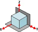
- Geometry tells us that three points are required to define a plane. This is the "3" in 3-2-1. So, three specific points are used to define the first plane.
- Fewer than three points cannot define a plane, and in the real world dimensional tolerances mean that four or more points will not be coplanar. A real-world, less than ideally perfect part placed on four or more reference points will, in fact, rest on only three of the points due to its less than perfect surface.
- Different parts may rest on different combinations of three points, resulting in variation between finished parts.
- A stool can be used to illustrate this concept. A two-legged stool would certainly be unstable. A three-legged stool sits rock-solid. A four-legged stool is often found to rock.
- In the illustration, a three dimensional part, represented by a cube, is placed on a datum plane defined by three support points. The part’s six degrees of freedom have now been reduced to three. It can still move along the X or Y axes, and it can still be rotated about the Z axis. (The part cannot move along the Z axis because it is held against the plane by clamping force.
TIPS
- Use the largest surface of the part for the first ("primary") reference plane.
- Position the three support points as far apart as possible.
- If more than three support points are required to prevent deflection, make the additional points adjustable.
Second Plane
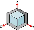
- A second plane, if it is perpendicular to the first, can be defined by two points, the "2" in 3-2-1.
- The part is now constrained to one degree of freedom: movement along the Y axis. (The part cannot move along the X or Z axes because it is held against the planes by clamping force.)
Third Plane
- A third plane, if it is perpendicular to both of the first two planes, can be defined by one point, the "1" in 3-2-1. The part is now entirely constrained. It cannot move along or rotate about the X, Y, or Z axes. (Remember that the part is held against each of the three planes by clamping force.)
TIPS
- If more than one support point is required to prevent deflection, make the additional points adjustable.
Machined is Best
It’s best if the workpiece surfaces intended to contact the support points are machined. Cast surfaces are usable, but then tend to create tolerance problems. Machined holes are the number one choice. Two machined holes can be used to eliminate all but one degree of freedom.
Repeatability
- Repeatability is a paramount concern. It means that each part should be nearly identical to each other part coming off the same fixture. "Nearly identical" actually has a specific, quantifiable meaning: key dimensions of all parts produced on the same fixture must fall within defined tolerances.
- In order to stay within tolerances, it’s best if the workpiece surfaces intended to contact the support points are machined. Cast surfaces are usable, but they tend to create tolerance problems. Machined holes are the number one choice, because two machined holes can be used to eliminate all but one degree of freedom.
- The next best feature to use for consistent locating is machined surfaces at right angles. The "machined surface" desired here can simply be a tab or small flat specifically included for locating purposes.
- Repeatability is achieved through application of the 3-2-1 method to the three aspects of the locating process:
1. Supporting
2. Locating (positioning)
3. Holding
Supporting
- The part is supported from "below" with reference to the Z axis. (Introduction of the first reference plane.)
- Gravity positions the part against the support locator.
- Provide adjustable auxiliary support points as needed to prevent deflection.
- Vertical location with respect to the fixture is now established
- The part is positioned horizontally, in the X-Y plane. (Introduction of the second and third reference planes.)
Holding
- The part is clamped against fixed locators. Therefore, a known and unvarying position of the part is maintained with respect to the X, Y, and Z axes.
- One strap clamp or clamp arm will restrict the workpiece in three dimensions due to friction between the workpiece and clamp. However, friction alone may not be enough to prevent the workpiece from moving during machining.
- Cutting forces will not move a properly supported and clamped part.
Locating
- The part is positioned horizontally, in the X-Y plane. (Introduction of the second and third reference planes).
Summary: Clamping rules of thumb
- Define three reference planes on the workpiece and fixture.
- Provide one opposing clamping force opposite each plane to restrict movement.
- When in doubt, rely on additional cylinders to take up uncertainty.
6)Define Body coordinate system?
Coordinate system is a reference system Consisting of a set of point, Lines & surfaces used to define position of point in space either in 2 or 3 dimensions.
In general BCS is also called as car line or Body line
Car lines are the (Grid lines) shown on the fixture, which virtually represent the same location in the BIW. All the car line on fixture display the coordinate at corner for reference. With these lines one can easily relate the, location in BIW.
Some times single coordinate hole is given in the fixture, that also represent the car line coordinates, from that reference point fixture is made and can be inspected. Body coordinate are mentioned near the hole
-We should try that the co-ordinates of locating and clamping points should not be in three decimal (e.g. X=100.124, Y=245.127, Z=450.458).
They should be in the whole nos. or max upto 1 decimal . Once these co-ordinates are maintained automatically the BIW base structure is maintained.
All vehicle product drawings are identified numerically relative to three vehicle planes Description shown below.
1. ( X ) It is in width of BIW – 0 X - is Body Center Line
2. ( Y ) It is in length of BIW – 0 Y is Near Front Bumper
3. ( Z ) It is in Height of BIW - 0 Z is about Center of Wheel
7)Elaborate Body plane system & its essentials.
Body planes are three mutually perpendicular imaginary planes. These are reference planes in automotive car. These are used to define GD & T of all parts in automotive domain.
The measurement from body plane to parts are called bodyplane dimensions.
Bodylines dimensions are essential for below reason
- It defines exact position of each product in the vehicle w.r.t a fixed origin.
- It ensures flawless design for assembly.
- While designing lines, all the designs are carried out relative to the bodylines viz.fixtures, Turntables etc.
- It assist in easy location of different parts in the vehicle.
- It aims in creating a standardized system.
- It assist in quality checks.
Some examples which shows how we use body plane to define the exact position of part is shown below.
fig-shows the use of x plane to define the length
fig-shows the use of z plane to define the height
fig-shows the use of y plane to define the width