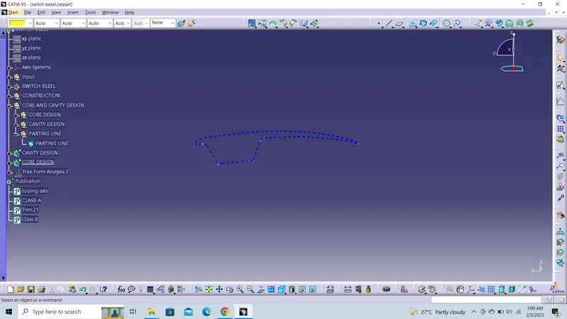
Week 8 - Challenge 6 - Core & Cavity Design
Core & Cavity Blocks of Switch Bezel:
- Import of the Molded Part (Skrinkage operation during the Import operation)
- Direction management (Add Main Pulling direction, Add Slider direction, Add Axis system)
- Mold area management (Move faces from a Mold area to an other, Split faces, Add Faces in a Mold area)
- Extract Parting Line
- Reflect Line
- Reference Element (Point, Line, Plane)
Draft extract :
- Main pulling direction definition based on Draft analysis of the Molded Part
- Exploded view of the different area : new visualization mode that allows user to separate skins according to their pulling directions (red and green skins). This is a visual method to enhance readability of the moldability of the part.
- Slider Direction definition based on draft analysis on a given mold area
- Assisted extraction of the Mold areas
- Associativity in the definition of the main pulling direction
– Core & Cavity and undercuts areas are recomputed when you modify the input of main pulling direction
Import of Part design data (solid or surfacic) and scaling application… User is able to use any Design Part that is a solid or a volume created with CATIA or any other system. The part is positioned into local current avis system that can be created from : the existing local axis system of the design Part if it exists, the bounding of the Part, the gravity center of the Part or even user coordinates. To take in account the shrinkage during molding operation, user has the ability to apply affinity or scaling.
Main pulling direction definition… Based on draft analysis criteria, this tool is used to identify Core & Cavity and undercuts area. Compass is used to define easily and interactively the right pulling direction. The Part is automatically divided in 3 sets, related to the selected associative pulling direction. So that, Core & Cavity and undercuts areas are recomputed when you modify the input of main pulling direction. User can easily spot the divided parts due to the following color mapping : green faces can be unmolded, red faces can be unmolded in the opposite direction and blue faces need to be part of slider, loose core or to be splitted.
Slider Pulling Direction definition… Based on draft analysis criteria, this tool enables designers to identify slider surface from the previously identified undercuts area. Compass is used to define easily and interactively the right slider direction. The Part is automatically divided in 2 sets. The green faces can be unmolded in the slider direction and the blue one need to be part of an other slide, loose core or to be splitted.
Molding areas detailing… Designer can use Cut, Copy, Paste and Split of faces from a molded area to an other one. Advanced tool helps the user to perform several operations in one step. For instance, Cut and Paste of faces from a molding area to an other can be achieved in a single operation. User can also split an area and distribute the result in the molding areas
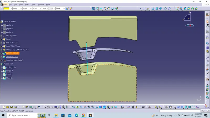
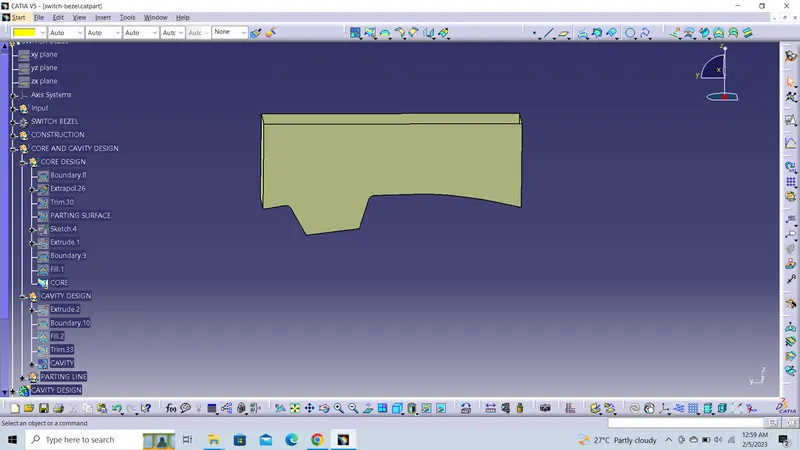
CORE
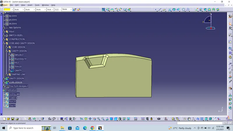
CAVITY
PARTING LINE