Week 8 - Challenge 3 - Coin Holder Design
DESIGN OF COIN HOLDER
AIM:
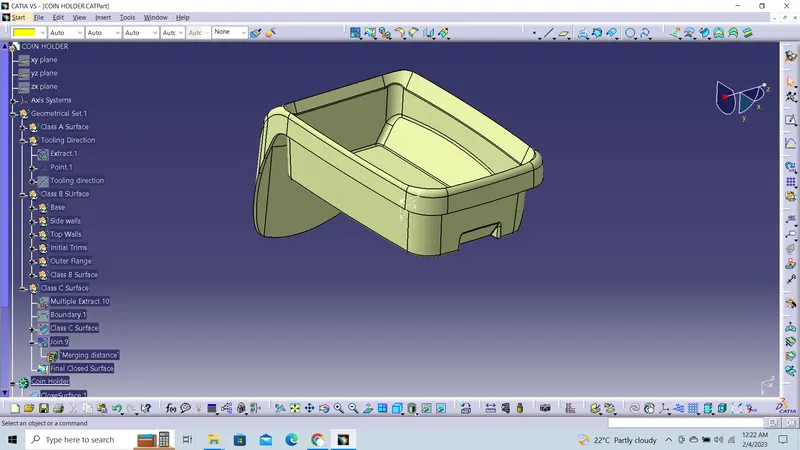
To create the coin holder plastic component through the given Class A surface. To begin with the tooling axis for the given Class-A surface should be created meeting the requirements of the draft angle and at the end perform the draft analysis on the model. Take the thickness of the component to be 2.5mm.
DESCRIPTION:
Class A surface: Class-A surfaces is a term used in most in automotive design to describe a set of freedom surfaces of high efficiency and quality.
Class B surface: Class B surfaces are the secondary surfaces that you can we see
sometimes but are less important.
Class C surface: Class C surface are the surfaces which connects the class A and Class B
surfaces.
Draft analysis: Draft analysis is performed on components where the ejection of materials
happen after the material is made inside the tools.
Design procedure:
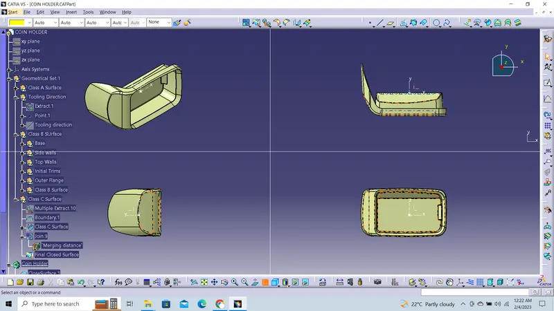
Checking Class A input for imperfections.
The input Class A surface is checked for the discontinuities and joined together to get
complete Class A surface as one.
TOOLING AXIS CREATION:
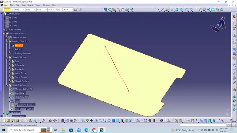
Generally tooling axis is created using bisecting line method. But
in the components where it has a bin, then the tooling axis is considered as a line normal to
the base surface of bin. Same is done with this component. A line normal to base surface is
created and considered as tooling axis.
DRAFT ANALYSIS ON CLASS-A SURFACE:
- Go to insert> analysis> feature draft analysis
- Align the tooling axis with the compass.
- Click on the surface and see that the surface is within the permissible limit of the draft values.
- The surface should be green and in the column nominal value 3deg given as input. hence the draft analysis on the class-A surface is successfully performed.
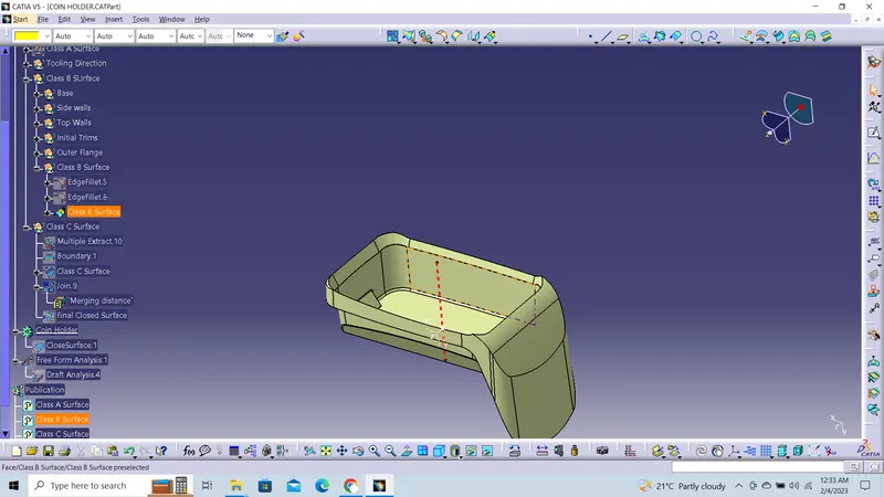
CLASS-B SURFACE CREATION:
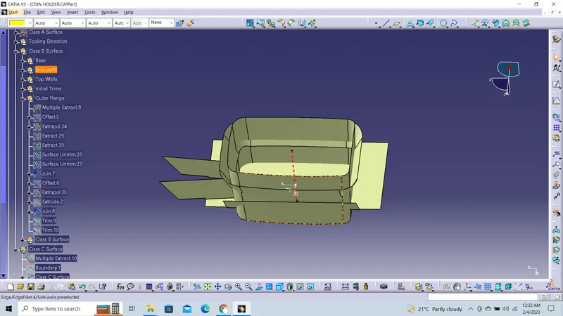
- For creating the class-B surface the required surface except the offset surface have been extracted and then untrimmed all the surface.
- Then all the surfaces have been extrapolated to get intersections between them.
- Since the thickness of the coin holder is 2.5mm the B-Surface was offset to 2.5 mm and the required trim operations must be carried out.
- Finally, the required corners have been filleted
CLASS-C SURFACE CREATION:
- The required outer edges of the A-Surface were extracted using Boundary.
- Then by using the sweep command the surface was created with the following feature controls,
- Profile type – Line
- Subtype – With Draft Direction
- Guide Curve – Smooth Curve
- Draft Direction – Tooling Axis
- Draft Computation Mode – Square
- Angle – 3 Degree
- Angle Sector – Positive Downward (1)
- Length – 20mm
- Then by using extrapolate command the edges were intersected between the surface corners which eases the trimming operation.
- Now the required portion of the C – surface were trimmed out.
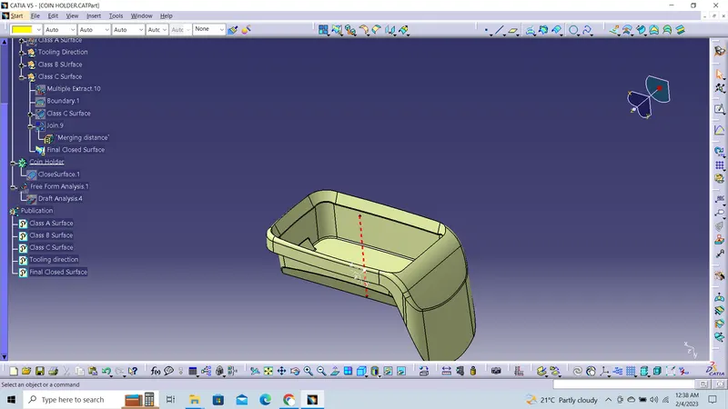
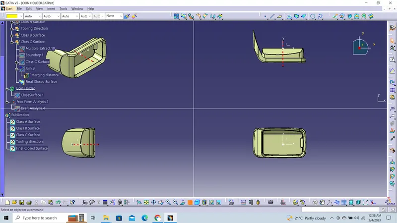
closed surface
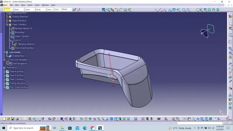
Conclusion:
- Created the Tooling axis
- Created CLASS B and CLASS C surfaces out of given CLASS A as input.
- Generated Solid body component from closed surface part.
- Used the main tooling axis for creating draft analysis on the component.
Hence, we have successfully created CLASS B and CLASS C surfaces using given CLASS A, resulting in closed surface part. This surface part is converted to solid plastic component. Used bisecting method for main tooling direction and learnt about importance of draft angle and tooling axis for plastic manufacturing process.