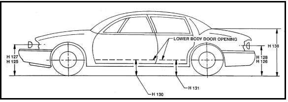
Week 2:- BiW Fixture Basics Challenge
1. Process of project execution activity
Project activities are those basically are being processed or being practiced in general project of BIW begins. Project activities are task from start to end of project. There are various step involved in project. Below fig. show flow chart of project activities.
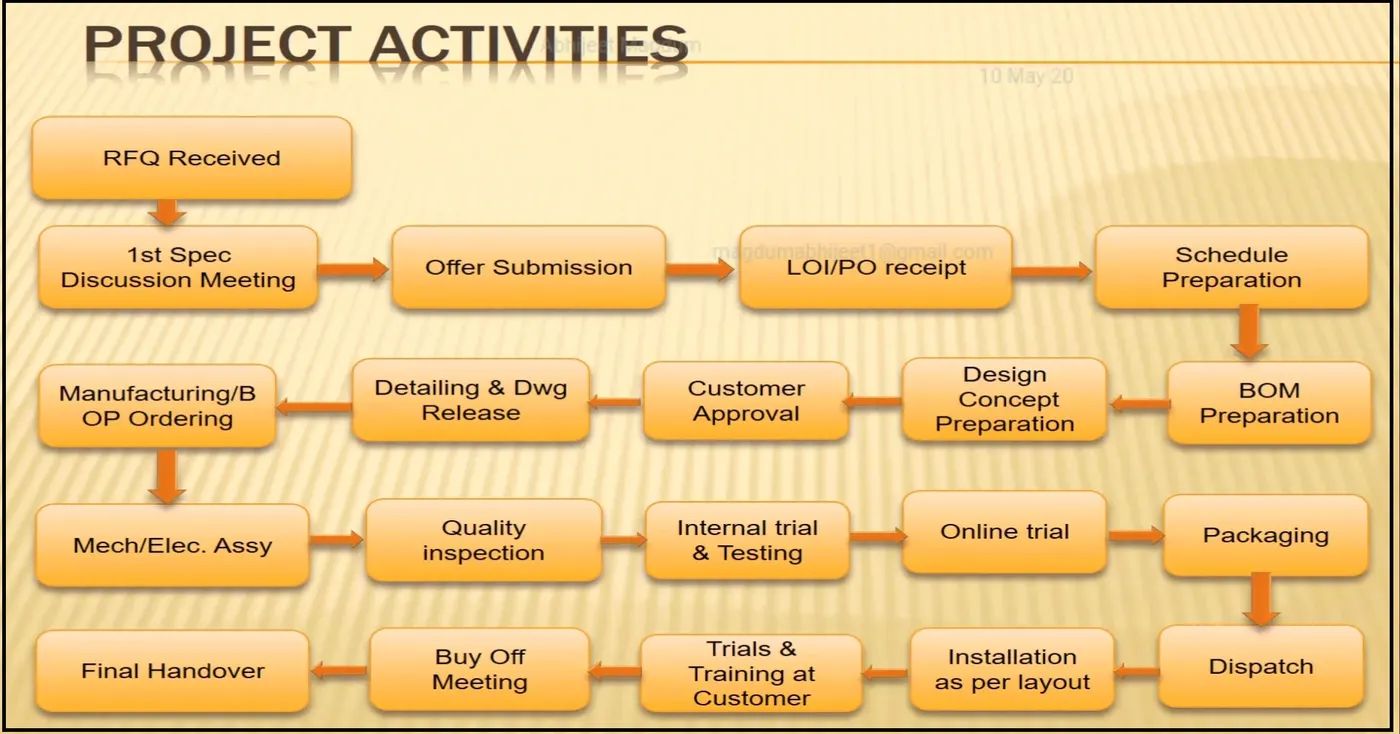
RFQ:
In BIW fixture design project begins. It starts with basic requirement or RFQ that we receive from customer. RFQ means request for quotation where in customer give his requirement specification etc. in form of some document or data to study or to work on information include such as technical offer, commercial offer, timeline of project Based on that we have processing to execute project.
1st specification discussion meeting & offer submission:
In this the documents related technical offer, commercial offer, project execution, timeline required to complete the project are prepared. The time required to 3D design, analysis of design, drawing & detailing, manufacturing, assembly & commissioning etc. is considered. Then cost of all operation is considered. By considering these kinds of things the offer is prepared & submitted to customer. Below fig. show document that how technical offer is made.
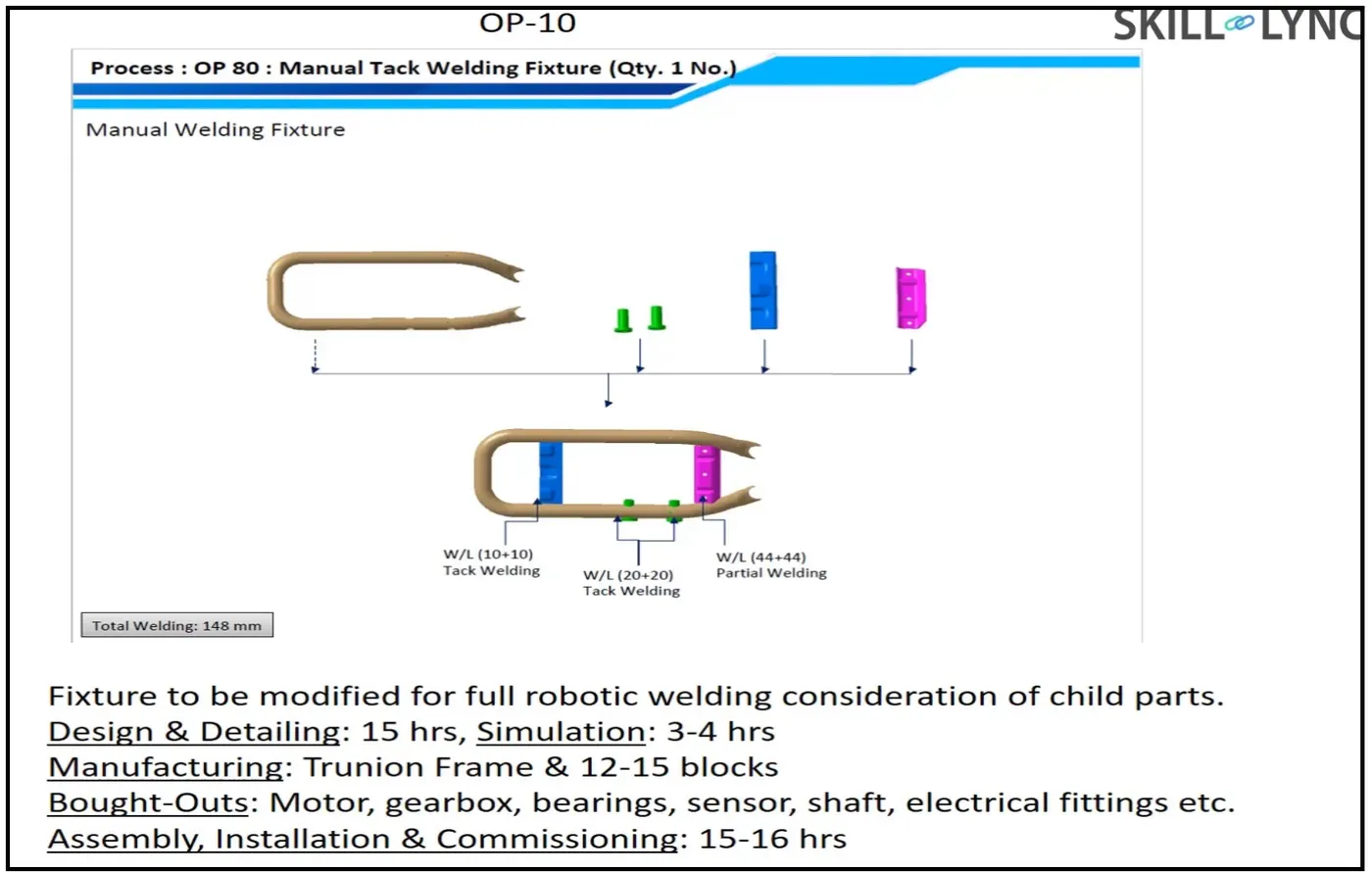
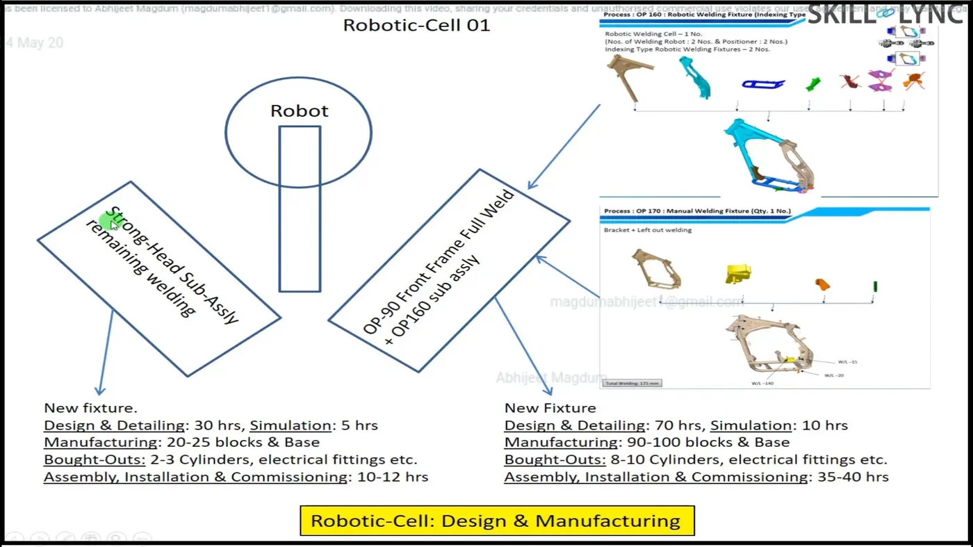
These are technical offer based on this commercial offer will be placed.
PO/LOI: Once we submitted offer customer will study the offer at the same time he will get offer from different supplier & vendor. He compares these technical offers & based on cost whichever suit best for his requirement. Then he will release LOI or PO with its terms & conditions as stated earlier.
Schedule Preparation: In project each activity depends on previous activity. So if previous activity has not completed on time it will cause delay in next activity date is fixed so that it will move further. Each activity has assigned specific time i.e. when activity is starting & when it is ending? So we have some back plan so that final date comes to close final delivery date. There need to be proper scheduling to be done to complete project in time. “On time delivery” is one of the major requirements from customer side also customer wants commitment must be follow in respect of time.
BOM Preparation: BOM preparation is listing down of part list which includes bought out parts, vendor parts, and consumable items with qty. of each item. Through BOM preparation material budget will be fixed. B/O parts include motor, gear box, cylinder, pneumatic & hydraulic valves etc. Also vendor parts include all machined, fabricated parts etc. whereas consumable includes like oil, grease, glue, loctite etc. .
Design concept preparation: Further step is to design a concept. A concept is based on all specification, received data from customer as 3D data of car panel, drawing, drawing std., design std., manufacturing std. After studying all data design concept is build.
Customer approval: As design concept ready then it is send to customer for its approval. It is also known as design approval process (DAP) or customer approval process. In that customer will check that all his specification consider or not in specifications. Whether it is as per technical offer submitted then only he approves prepared concept. Some points will be raised by customer. These changes are updated to design team by project team. Design team again work on it some modification or changes are necessary to improve design like clamping need to be improved or this mechanism will work fine, sensor should be of this make. These changes are again updated to customer. Once he gave final approval we will move further for detailing & dwg. release.
Detailing & Dwg. release: In detailing all assemblies broken down into its child parts. Parts of assembly are segregated into std. as well as manufactured. For std. parts own data sheet or specification sheet prepared to purchase it from catalogue. e.g. motor power, motor current rating, torque produced, shaft rpm which suit for our application. For vendor parts all detail should be provided on dwg. Like all dimension of part with tolerance, surface finish, surface treatment, hardness, welding note all should be mention on dwg. These dwgs are checked & released for manufacturing.
Manufacturing & B/O ordering: Manufacturing department will receive all dwg to start manufacturing of items like mylar, blade, riser, base frame. Also purchase team will place order for B/O parts like motor, gearbox, cylinder & valves. As material get ready, QC team should inspect all part received is as per specification or not otherwise it will create issue later which will waste our time
Mechanical & electrical assembly: After qc check, parts are available for assembly. A station is integration of all mechanical as well as electrical assembly. Assembly team will do all assembly as per dwg. All station are build as per layout Then again qc team should be involved for checking assembly as per final dwg., all coordinate dimension should be ok as per design data.
Internal trial & testing: After approval of qc team, Internal trials & testing started. The first step involves putting assembly in fixture manually to check that it being fix properly, locating pin match with hole, clamping is ok, loading & unloading of part is easy. Also operating height is also checked, it is ergonomically correct. Then start taking trials on fixture for welding feasibility, gun approachability in fixture. Then go for online trial.
Online training: After successful of trial next step is online training. In online training has two mode manual & automated. In online trial system is run through control panel. All sensor, actuator, motor current & temperature, noise, all alarm, also safety should be tested. All process must be executed as per sequence also cycle time meet. In online training system run for certain cycle & actual production taken to ensure system run successfully.
Packaging: After trial get successful, customer give approval to dispatch system. To dispatch whole system needs to disassemble station wise & pack properly. Delicate material should be packed properly otherwise there is chance of damage aesthetically or functionally during transportation. During packaging labeling, special handling instruction should be pasted on particular parts to convey message of taking care during handling & transportation.
Dispatch: All material transported at customer site through trucks, container, and ships or by air.
Installations: All system is assembled & installed at customer end as per layout approved initially in DAP. All station, robots, conveyor mounted as per distance specified in layout. Robot arm should be reachable to station, pick & drop point. It shouldn’t foul with other equipment. Also some adjustment should be provided for leveling purpose at robot conveyor base, station base frame like leveling stud to align with other equipment. Layout is always specified at the time of initial design stage & it has to be approved by customer.
Trial & training at customer end: Once installation is done trial start at customer end. So there will be production trial, online trial. Production trial is necessary because at the time of designing fixture, it also committed no. of unit that will be manufactured from that fixture also whether it is meeting quality, bench mark or not. Also in technical offer it is committed that there will be 100 units per 8hrs shift will manufactured from that fixture with weld quality. So during production trial fixture capability will be ensured. Once this goal is achieved then there will be training to operator, staff member, engineers to let them to understand how process is working?
Buy off meeting: Once training is completed there is buy off meeting between customer & project team with discussion on if there other things need to be incorporated, anything missing that described in LOI/PO or offer submission. Then customer will raise point or sometimes customer wants modification that will lead to extra quotation, extra costing according work is done as per buy of meeting.
Final handover: Once all points raised by customer will be closed then all will go for final handover. All data, technical manual, soft hard documents will submit to customer. These are main project activity.
2. Joining processes:
- JOINING COMPRISES a large number of processes used to assemble individual parts into a larger, more complex component or assembly.
- The individual parts of a component meet at the joints.
- Joints transmit or distribute forces generated during service from one part to the other parts of the assembly.
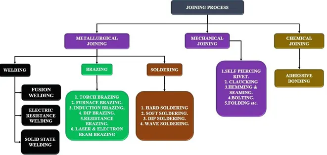
Types of joining process
- The durability & performance of any structure largely depends on the quality & the design of the component joints.
- The whole structure cannot be made in one piece.
- Two fundamental options for joining materials & components are,
- Metallurgical joining
- Mechanical joining
- Chemical joining
1. Metallurgical joining:
- Metallurgical joining are classified into,
- Welding.
- Brazing.
- soldering.
i. Welding:
- The process of joining similar metals by the application of heat is called Welding can be obtained with or without application of pressure and with or without the addition of filler metal, which is known as an electrode. During welding, the edges of these metal pieces are either melted or brought to plastic condition. The welding process is used for making permanent joints, which is obtained by a homogeneous mixture of two materials.
Classification of Welding Process: The types of welding process classified into,
- Fusion
- Electric Resistance
- Solid-state
a. Fusion Welding.
- In infusion welding, the metal at the joint is heated to a molten state, and then it is allowed to solidify.
- The pressure is not applied during the welding process and hence it is also called 'non - pressure welding'.
- Filler materials may be required during this type of welding.
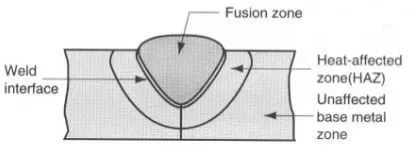
- Classification of fusion welding is,
- Thermit welding
- Arc welding
- Gas welding
I. Thermit Welding
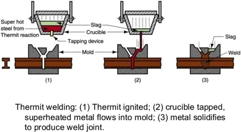
- Welding the parts by using liquid thermit steel around the portions to be welded is called thermit welding. Since it is a fusion welding process, neither arc is produced to heat parts nor flames are used. For getting high temperatures, the exothermic reaction is used.
- The welding principle is the heat of the thermit reaction used for welding in a plastic state & mechanical pressure is applied for the joint.
- It is depending on the chemical reaction between iron oxide & aluminum.
- The reaction in thermit welding is 8Al + Fe3O4 = 9Fe + 4Al2O3. This reaction takes place about 30 sec only and the heat liberation temperature is about 2800 degree Celcius. It is twice the melting temperature of steel.
II. Arc Welding:
- In the arc welding process, the heat is developed by an electric arc. The arc is produced between an electrode and the work. This is a process of joining two metal pieces by melting their edges with an electric arc. In arcwelding the electrical energy is converted into heat energy.
- The electrode & the workpiece are brought nearer with similar a small air gap of 3mm approximately. Then the current is passed through the workpiece and the electrode to produce an electric arc.
- The workpiece is melted by an arc, The electrode is also melted, and hence both the workpieces become a single piece without applying any external pressure. The temperature of the arc is about 5000°C to 6000°C. The electrode supplies additional filler metal into the joints and is deposited along the joint. A transformer or generator is used to supply current. The depth to which the metal is melted and deposited is called the depth of fusion. To obtain a better depth of fusion, the electrode is kept at 70° inclination to the vertical.
- The electrode used in arc welding is generally coated with flux. The flux is used to prevent the reaction of the molten metal with atmospheric air. Also, it removes the impurities of the molten metal and forms a slag. This slag gets deposited over the weld metal. This slag protects the weld seam from rapid cooling.
- The molten metal is forced out of the pool by the electric arc. Hence a small depression is formed in the parent metal where the molten metal is oiled up. This is known as "arc carter".The distance between the tip of the electrode and the bottom of the arc crater is called "arc length".
The types of arc welding are,
Manual Metal-Arc
- Aiming for cleaner, high-quality welds at a lower cost. Manual Metal Arc (MMA) welding is the most flexible and one of the most widely used arc welding processes. It involves striking an arc between a covered metal electrode and a workpiece.
MIG
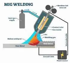
- MIG—i.e., metal inert gas—welding is generally used for large and thick materials. It employs a consumable wire that acts as both the electrode and the filler material. Compared to TIG welding, it is much faster, resulting in shorter lead times and lower production costs
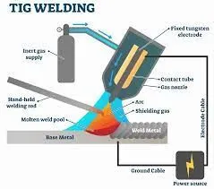
TIG
- In TIG welding, a tungsten electrode heats the metal you are welding, and gas (most commonly Argon) protects the weld puddle from airborne contaminants. TIG welding produces clean, precise welds on any metal.
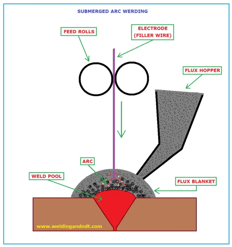
Submerged Arc
- Submerged arc welding (SAW) is so named because the weld and arc zone are submerged beneath a blanket of flux. The flux material becomes conductive when it is molten, creating a path for the current to pass between the electrode and the workpiece.
Plasma Arc
- Plasma arc welding is an arc welding process similar to gas tungsten arc welding. The electric arc is formed between an electrode and the workpiece. The key difference from GTAW is that in PAW, the electrode is positioned within the body of the torch, so the plasma arc is separated from the shielding gas envelope.
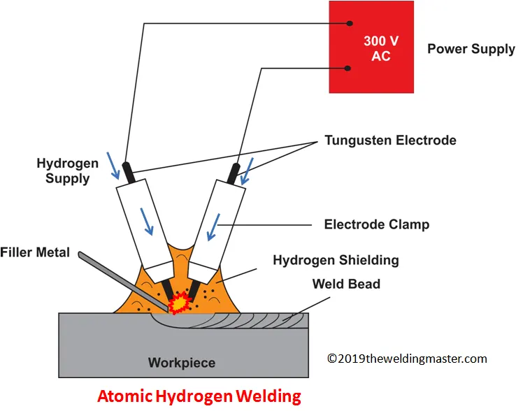
Atomic hydrogen Arc
- Atomic hydrogen welding (AHW) is an arc welding process that uses an arc between two tungsten electrodes in a shielding atmosphere of hydrogen. The process was invented by Irving Langmuir in the course of his studies of atomic hydrogen.
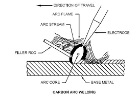
Carbon Arc
- Carbon arc welding (CAW) is a process that produces coalescence of metals by heating them with an arc between a non-consumable carbon (graphite) electrode and the work-piece
Electro slag
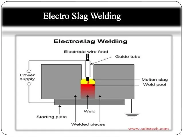
- Electroslag welding (ESW) is a highly productive, single-pass welding process for thick (greater than 25 mm up to about 300 mm) materials in a vertical or close to a vertical position. (ESW) is similar to electro gas welding, but the main difference is the arc starts in a different location.
III. Gas welding
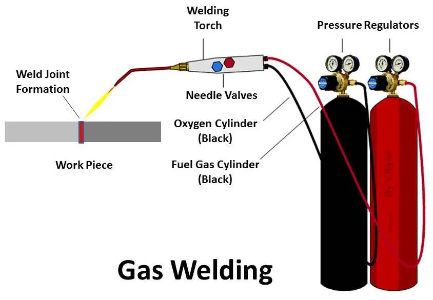
- Gas welding is a welding process that melts and joins metals by heating them with a flame caused by a reaction of fuel gas and oxygen.
- The most commonly used method is
- Oxyacetylene welding, due to its high f la me the temperature.
- The flux may be used to deoxidize and cleanse the weld metal.
- The flux melts solidify and forms a slag skin on the resultant weld metal.
. Electric Resistance Welding:
- Resistance welding is a welding technique widely used in the manufacturing industry for joining metal sheets & This type of welding is very much used in BIW assemblies most common.
- The weld is made by conducting a strong current through the metal combination to heat up & finally melt the metals at localized points predetermined by the design of the electrodes or the workpiece to be welded.
- A force is always applied before, during, and after the application of the current to confine the contact area at the weld interfaces and in some applications to forge the workpieces.
Types of Resistance welding are,
- Resistance Spot welding
- Resistance Seam welding
- Resistance Projection welding
1. Resistance spot Welding:
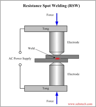
- The process is used for joining sheet materials & uses shaped copper - chromium or zinc conium alloy electrodes to apply pressure and convey the electrical current through the workpiece.
- Heat is developed mainly at the interface between two sheets, eventually causing the material being welded to melt, forming a molten pool, the weld nugget.
- The molten pool is contained by the pressure applied by the electrode tip & the surrounding solid metal.
2. Resistance Seam Welding:
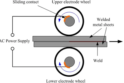
- Seam welding is a resistance welding process for joining metal sheets in continuous, often leak-tight, seam joints by directly applying opposing forces with electrodes consisting of rotary wheels.
- The current & the heat generation are localized by the peripheral shapes of electrode wheels.
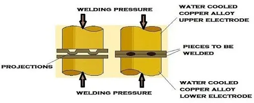
3. Resistance Projection Welding:
- Projection welding is a resistance welding process for joining metal components or sheets with embossments by directly applying opposing forces with electrodes specially designed to fit the shapes of the workpieces.
- The current & the heat generation are localized by the shape of the workpiece either with their natural shapes or with specially designed projection.
- Large deformation or collapse will occur in the projection part of the workpieces implying high.
C. Solid-State Welding:
- Solid-State Welding is a welding process, in which two workpieces are joined under a pressure providing intimate contact between them and at a temperature essentially below the melting point of the parent material. The bonding of the materials is a result of the diffusion of their interface atoms.
The following processes are related to Solid State welding:
- Forge welding
- Cold welding
- Friction welding
- Explosive welding
- Diffusion welding
- Ultrasonic Welding
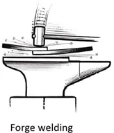
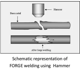
1. Forge Welding:
- Forge Welding is a Solid-state welding process, in which low carbon steel parts are heated to about 1800°F (1000°C) and then forged (hammered).
- Prior to Forge Welding, the parts are scarfed in order to prevent entrapment of oxides in the joint.
- Forge Welding is used in general blacksmith shops and for manufacturing metal art pieces and welded tubes.
2. Cold Welding (CW):
- Cold Welding is a Solid-state welding process, in which two workpieces are joined together at room temperature and under a pressure, causing a substantial deformation of the welded parts and providing intimate contact between the welded surfaces.
- As a result of the deformation, the oxide film covering the welded parts breaks up, and clean metal surfaces reveal. Intimate contact between these pure surfaces provides a strong and defectless bonding.
- Aluminum Alloys, Copper Alloys, low carbon steel, Nickel Alloys, and other ductile metals may be welded by Cold Welding. Cold Welding is widely used for manufacturing bi-metal steel - aluminum alloy strips, for cladding of aluminum alloy strips by other aluminum alloys, or pure aluminum (Corrosion protection coating).
- Bi-metal strips are produced by Rolling technology. Presses are also used for Cold Welding.
- Cold Welding may be easily automated.
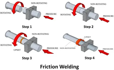
3. Friction Welding (FRW):
- Friction Welding is a solid-state welding process, in which two cylindrical parts are brought in contact by a friction pressure when one of them rotates. Friction between the parts results in heating their ends. Forge pressure is then applied to the pieces providing formation of the joint.
- Carbon steels, alloy steels, tool & die steels, adequate steels, aluminum alloys, copper alloys, magnesium alloys, Nickel alloys, Titanium alloys may be joined by Friction Welding.
4. Explosive Welding (EXW):
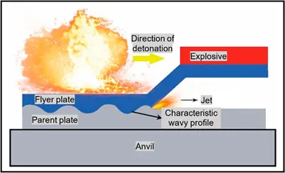
- Explosive Welding is a Solid-state welding process, in which welded parts (plates) are metallurgically bonded as a result of oblique impact pressure exerted on them by a controlled detonation of an explosive charge.
- One of the welded parts (base plate) is rested on an anvil, the second part (flyer plate) is located above the base plate with an angled or constant interface clearance.
- An explosive charge is placed on the flyer plate. Detonation starts at an edge of the plate and propagates at high velocity along with the plate.
- The maximum detonation velocity is about 120% of the material sonic velocity.
- The slags (oxides, nitrides, and other contaminants) are expelled by the jet created just ahead of the bonding front. Most of the commercial metals and alloys may be bonded (welded) by Explosive Welding.
- Dissimilar metals may be joined by Explosive Welding: Copper to steel; Nickel to steel; Aluminium to steel; Tungsten to steel; Titanium to steel; Copper to aluminium.
- Explosive Welding is used for manufacturing clad tubes and pipes, pressure vessels, aerospace structures, heat exchangers, bi-metal sliding bearings, ship structures, weld transitions, corrosion-resistant chemical process tanks.
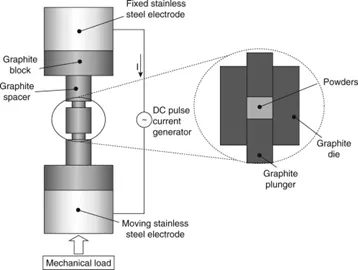
5. Diffusion Welding (DFW):
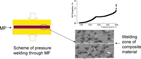
- Diffusion Welding is a Solid-state welding process, in which pressure applied to two workpieces with carefully cleaned surfaces and at an elevated temperature below the melting point of the metals. The bonding of the materials is a result of the mutual diffusion of their interface atoms.
- In order to keep the bonded surfaces clean from oxides and other air contaminations, the process is often conducted in a vacuum.
- No appreciable deformation of the workpieces occurs in Diffusion Welding. Diffusion Welding is often referred to more commonly as Solid-state welding.
- Diffusion Welding is able to bond dissimilar metals, which are difficult to weld by other welding processes: Steel to tungsten; Steel to niobium; Stainless steel to titanium; Gold to copper alloys.
- Diffusion Welding is used in aerospace and rocketry industries, electronics, nuclear applications, manufacturing composite materials.
6. Ultrasonic Welding (USW):
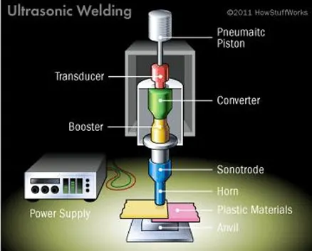
- Ultrasonic Welding is a Solid-state welding process, in which two workpieces are bonded as a result of pressure exerted on the welded parts combined with the application of high-frequency acoustic vibration (ultrasonic).
- Ultrasonic vibration causes friction between the parts, which results in a closer contact between the two surfaces with simultaneous local heating of the contact area. Interatomic bonds, formed under these conditions, provide strong joint. The ultrasonic cycle takes about 1 sec. The frequency of acoustic vibrations is in the range of 20 to 70 kHz.
- The thickness of the welded parts is limited by the power of the ultrasonic generator.
- Ultrasonic Welding is used mainly for bonding small workpieces in electronics, for manufacturing communication devices, medical tools, watches, in the automotive industry.
ii. Brazing:
Brazing is a metal-joining process in which two or more metal items are joined together by melting and flowing a filler metal into the joint, the filler metal having a lower melting point than the adjoining metal.
Brazing differs from welding in that it does not involve melting the work pieces and from soldering in using higher temperatures for a similar process, while also requiring much more closely fitted parts than when soldering. The filler metal flows into the gap between close-fitting parts by the capillary. The filler metal is brought slightly above its melting temperature while protected by a suitable atmosphere, usually a flux. It then flows over the base metal (known as wetting) and is then cooled to join the workpieces together. A major advantage of brazing is the ability to join the same or different metals with considerable strength.
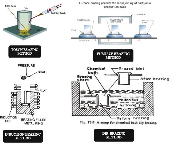
There are different methods/techniques in brazing. They are:
- Torch Brazing: In this method, acetylene, natural gas & butane, or propane are combined with air, or oxygen is used to supply the required heat to melt the filler rod and diffuse the base It is not used for mass production, and flues are used in the form of paste or powder.
- Furnace Brazing: In this process, the heat is supplied by gas or electric heating The furnace can be either box type or continuous type. The preformed shape of filler metal is placed on the parts to be joined before entering the furnace. The use of flux can be avoided if an inert atmosphere is maintained in the furnace. It is used for mass production and the flux is used in the form of a paste.
- Induction Brazing: In this process also, the filler metal is used in the form of preformed The parts are heated by placing within the field of a high-frequency induction coil. The electric and magnetic resistances of the changing induction field are used to produce the eddy current. This eddy current is used to heat the metal. It is also used for mass production and the flux is used in the form of a paste.
- Dip Brazing: The dip brazing is of two They are: i) Chemical dip brazing: In chemical dip brazing, the parts with preformed filler metal are placed into a molten bath of flux. This method is mainly used for joining large parts. ii) Molten metal bath process: In this process, the assembled parts are first prefixed & then immersed into a molten bath or filler metal. It is used only for joining smaller parts.
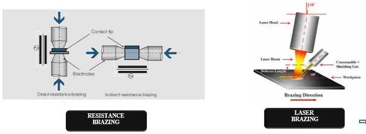
- Resistance Brazing: In this process, the filler metal is placed in the joint, Rapid heating minimizes oxidation and the heat-affected zone is
- Laser Brazing & Electron Beam Brazing: The laser & electron beam brazing methods are costly In laser brazing, the laser beam is used to join the metal and the beam produced by the heat source is used to join the metals in electron beam brazing. It is used only in precision work of high value & relating high-temperature materials.
iii. Soldering:
Soldering is a process in which two or more items are joined together by melting and putting a filler metal (solder) into the joint, the filler metal having a lower melting point than the adjoining metal. Unlike welding, soldering does not involve melting the workpieces. In brazing, the workpiece metal also does not melt, but the filler metal is one that melts at a higher temperature than in soldering. In the past, nearly all solders contained lead, but environmental and health concerns have increasingly dictated the use of lead-free alloy for electronics and plumbing purposes.
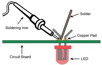
There are different types of soldering methods. They are:
- Hard soldering: In hard soldering, the filler metal is also known as silver soldering. This method is more expensive than plain brazing because the filler metal is more expensive. This hard soldering method is used for joining electrical & refrigeration parts.
- Soft Soldering: This is the most commonly used In this method soldering iron is a copper rod with a thin tip that is used for flattering the soldering material. The soldering iron can be heated by keeping it in a furnace or by means of electrical resistance. The filler material used in soft soldering is called soft solder.
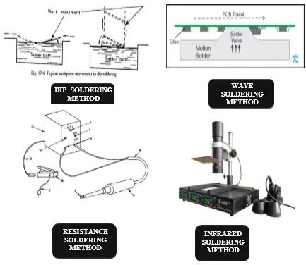
- Dip soldering: In this method, a large amount of solder is melted in a closed Then the parts to be soldered are cleaned & properly dipped in a flux bath as per the requirement. It is then dipped into the molten solder pool and lifted after completing soldering.
- Wave Soldering: It is a different method in which the parts to be soldered are not dipped into the solder tank but a wave is generated into the tank. So the solder comes up & the joint is made. It is used for the mass production of electronic equipment.
- The other methods of soldering are Oven soldering, Resistance soldering, Induction soldering & Infrared.
- Resistance & Induction soldering: In this method, electric energy is used to join the.
- Infrared soldering: In this method, the ultrasonic waves are used to join the.
2. Mechanical joining:
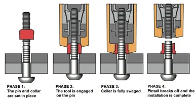
- Mechanical joining includes bolting, riveting, caulking, shrink fitting, Hemming, Seaming, and folding, all of which join workpieces by using mechanical
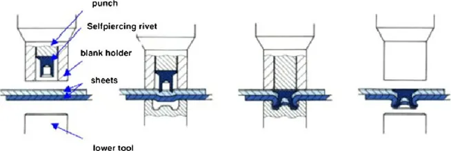
i. Self Piercing Riveting:
- It is a high-speed mechanical fastening process for point joining sheet material, typically steel & aluminum alloys.
- It is a single-step technique generally using a semi-tubular rivet to clinch the sheets in a mechanical joint.
- As the name suggests pre-drilled holes are not required, allowing the joint to be made rapidly in one operation.
ii. Hemming & seaming process:
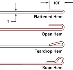
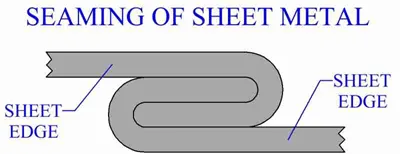
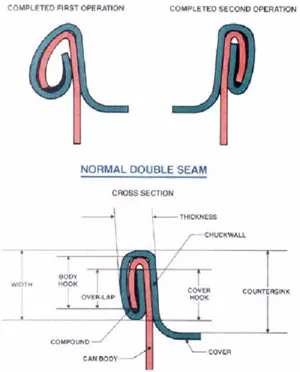
- Hemming & seaming are two similar metalworking processes in which a sheet metal edge is rolled over onto itself.
- Hemming is a process in which the edge is rolled flush to itself, while a seam joins the edges of two materials.
iii. Bolting:
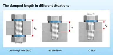
- Bolted joints are one of the most common elements in construction and machine design. They consist of fasteners that capture and join other parts and are secured with the mating of screw threads.
- There are two main types of bolted joint designs: tension joints and shear joints.
- In the tension joint, the bolt and clamped components of the joint are designed to transfer an applied tension load through the joint by way of the clamped components by the design of a proper balance of joint and bolt stiffness. The joint should be designed such that the clamp load is never overcome by the external tension forces acting to separate the joint. If the external tension forces overcome the clamp load (bolt preload) the clamped joint components will separate, allowing relative motion of the components.
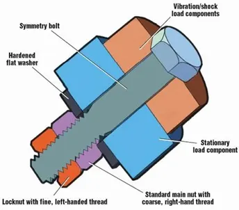
- The second type of bolted joint transfers the applied load in shear of the bolt shank and relies on the shear strength of the bolt. Tension loads on such a joint are only incidental. A preload is still applied but consideration of joint flexibility is not as critical as in the case where loads are transmitted through the joint in tension. Other such shear joints do not employ a preload on the bolt as they are designed to allow rotation of the joint about the bolt but use other methods of maintaining bolt/joint integrity. Joints that allow rotation include clevis linkages, and rely on a locking mechanism (like lock washer, thread adhesives, and locknuts).
Proper joint design and bolt preload provide useful properties:
- For cyclic tension loads, the fastener is not subjected to the full amplitude of the load; as a result, the fastener's fatigue life is increased or—if the material exhibits an endurance limit its life extends indefinitely.
- As long as the external tension loads on a joint do not exceed the clamp load, the fastener is not subjected to motion that would loosen it, obviating the need for locking mechanisms. (Questionable under Vibration Inputs.)
- For the shear joint, a proper clamping force on the joint components prevents relative motion of those components and the fretting wear of those that could result in the development of fatigue cracks.
In both the tension and shear joint design cases, some level of tension preload in the bolt and resulting compression preload in the clamped components is essential to the joint integrity. The preload target can be achieved by a variety of methods: applying a measured torque to the bolt, measuring bolt extension, heating to expand the bolt then turning the nut down, torquing the bolt to the yield point, testing ultrasonically, or by applying a certain number of degrees of relative rotation of the threaded components. Each method has a range of uncertainties associated with it, some of which are very substantial.
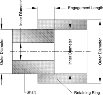
iv. shrink fitting:
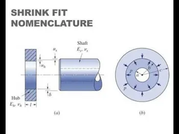
- Shrink-fitting is a technique in which an interference fit is achieved by a relative size change after assembly. This is usually achieved by heating or cooling one component before assembly and allowing it to return to the ambient temperature after assembly, employing the phenomenon of thermal expansion to make a joint. For example, the thermal expansion of a piece of a metallic drainpipe allows a builder to fit the cooler piece to it. As the adjoined pieces reach the same temperature, the joint becomes strained and stronger.
- Other examples are the fitting of a wrought iron tire around the rim of a wooden cartwheel by a wheelwright, or of a steel tire to the wheel of a railway engine or rolling stock. In both cases, the tire will be heated and expands to slightly greater than the wheel's diameter, and is fitted around it. After cooling, the tire contracts, binding tightly in place. A common method used in industry is the use of induction shrink fitting which refers to the use of induction heating technology to pre-heat metal components between 150˚C and 300˚C thereby causing them to expand and allow for the insertion or removal of another component. Other methods of shrink-fitting include compression shrink fitting, which uses a cryogen such as liquid nitrogen to cool the insert and shape memory coupling, which is achieved using a phase transition.
3. Chemical joining:
Chemical joining includes Adhesive bondings.
Adhesive Bonding:
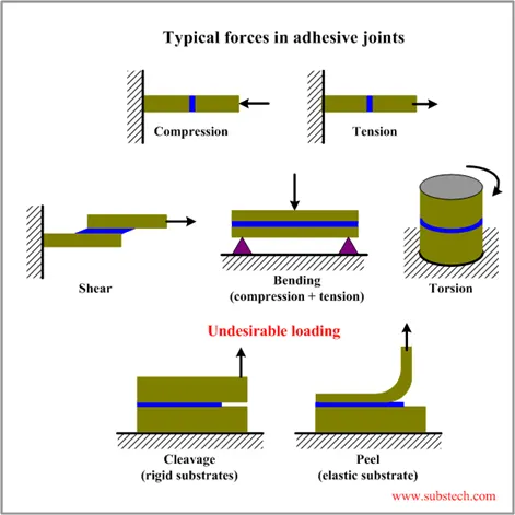
- Adhesive bonding is used to fasten two surfaces together usually producing a smooth bond.
- This joining technique involves glues, epoxies, or various plastic agents that bond by evaporation of a solvent or by curing a bonding agent with heat, pressure, or time.
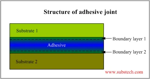
- Adhesive bonding (also referred to as gluing or glue bonding) describes a wafer bonding technique by applying an intermediate layer to connect substrates of different types of materials. Those connections produced can be soluble or insoluble. The commercially available adhesive can be organic or inorganic and is deposited on one or both substrate surfaces. Adhesives, especially the well-established SU-8, and benzocyclobutene (BCB), are specialized for MEMS or electronic component production.
- The procedure enables bonding temperatures from 1000 °C down to room temperature. The most important process parameters for achieving a high bonding strength are:
- adhesive material
- coating thickness
- bonding temperature
- processing time
- chamber pressure
- tool pressure
- Adhesive bonding has the advantage of relatively low bonding temperature as well as the absence of electric voltage and current. Based on the fact that the wafers are not in direct contact, this procedure enables the use of different substrates,
- e.g. silicon, glass, metals, and other semiconductor materials. A drawback is that small structures become wider during patterning which hampers the production of an accurate intermediate layer with tight dimension control.
- Further, the possibility of corrosion due to out-gassed products, thermal instability, and penetration of moisture limits the reliability of the bonding process.
- Another disadvantage is the missing possibility of hermetically sealed encapsulation due to the higher permeability of gas and water molecules while using organic adhesives.
3. Resistance welding & its application in automotive sector
- Resistance welding is technology widely used in manufacturing industry for joining sheet metal & component.
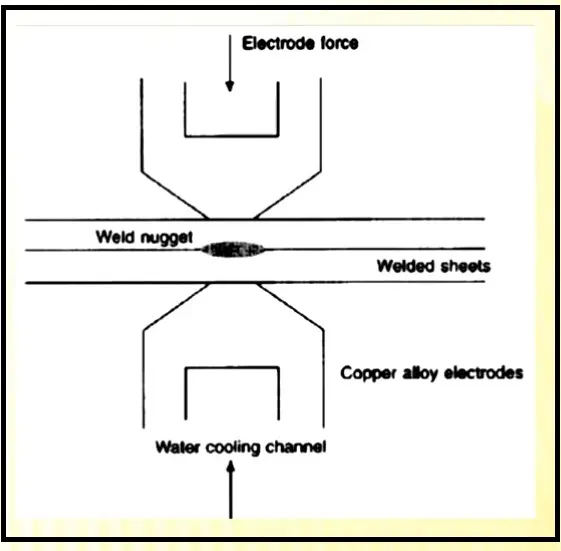
- The weld is made by conducting a strong current through metal combination to heat up & finally melts metal at localized points predetermined by the design of electrodes and or the work piece to be welded.
- A force is always applied before, during & after application of current to confine the contact area at weld interface & in some workpiece to forge the wokpiece. Below fig. shows resistance welding technique.
Types of resistance welding:
- Resistance spot welding
- Resistance seam welding
- Resistance projection welding.
1). Resistance spot welding-
Resistance spot welding widely used in BIW joining processes. The process is used for joining sheet materials & uses shaped copper chromium or zirconium alloy electrode to apply pressure & convey electrical current through the workpiece. Heat is developed mainly at interface between two sheet, eventually causing material being welded to melt, forming a molten pool & weld nugget. The molten pool is contained by the pressure applied by electrode tip & surrounding solid metal. When circuit is completed current will flow from that panel or sheet metal which will generate amount of heat that is sufficient enough to melt that will be melted & get welded together. The molten pool should not move outside of that zone to ensure that proper pressure is applied through electrode tip & surrounding sheet metal. Forcing a large current through the spot will melt the metal and form the weld. The attractive feature of spot welding is that much energy can be delivered to the spot in a very short time (approximately 10–100 milliseconds). That permits the welding to occur without excessive heating of the remainder of the sheet. Strength & durability largely depends on quality of RSW. Below figure illustrate principle of resistance welding.
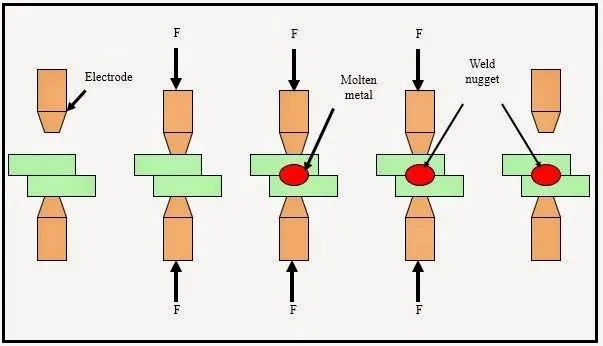
Following are advantages of resistance spot welding.
- Short weld time & hence high weld speed
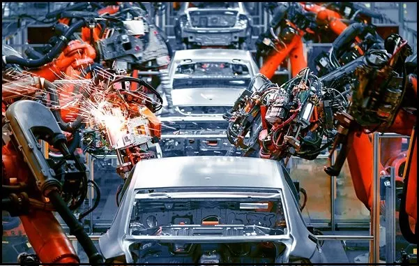
- Highly adaptable to automation & robotic technique. Below figure show robot used in automotive industry for spot welding. Typical BIW contains 500 weld. RSW is automated and used in the form of robotic spot welding in automotive industries to weld the sheet metals to form car body. Below figure illustrate typical application of spot welding using robots.
2).Resistance seam welding:
Resistance seam welding is welding process for joining metal sheets in continuous, often leak tight, and seam joints by directly applying opposing forces with electrode consisting of rotary wheel. It differs from flash welding in that flash welding typically welds the entire joint at once and seam welding forms the weld progressively, starting at one end. The current & the heat generation are localized by peripheral shapes of electrode wheel Seam welding is mostly applied in manufacturing of containers radiators & heat exchangers etc. Resistance seam welding is used where leakage proof continuous welding required. Like spot welding, seam welding relies on two electrodes, usually made from copper, to apply pressure and current. The electrodes are often disc shaped and rotate as the material passes between them. This allows the electrodes to stay in constant contact with the material to make long continuous welds. The electrodes may also move or assist the movement of the material. Seam welding produces an extremely durable weld because the joint is forged due to the heat and pressure applied. A properly welded joint formed by resistance welding can easily be stronger than the material from which it is formed. A common use of seam welding is during the manufacture of round or rectangular steel tubing. Seam welding has been used to manufacture steel beverage cans but is no longer used for this as modern beverage cans are seamless aluminum. In automobile industries, this welding process is used to produce leak proof fuel tanks.
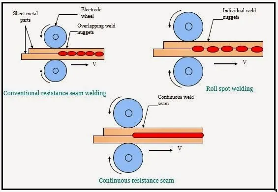
3).Resistance projection welding:
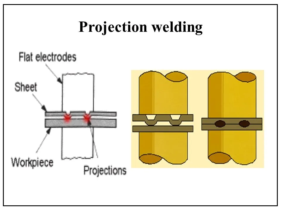
Projection welding is process for joining metal components or sheets with embossment by directly applying opposing forces with electrode specially designed to fit the shape of workpieces. The current & heat generation are localized by shape of workpieces either with their natural shape or with specially designed projection. Large deformation or collapse will occur in projection part of workpiece. This process has the benefit of forcing the welds to occur in very specific and tiny locations, and minimizing the dissipation of heat to the rest of the metal sheets.
It used for mechanical fixing of auto body structure e.g. to weld nut. In BIW body there will be many welded nut, stud, bolt that need to be welded on sheet. It will use further stages for fastening process. So to weld these things we use process like resistance welding. Concept & mechanism is same to use two electrodes. The current will flow, pressure will be applied metal will melt & get welded together. Spot welding will have rounded tip at end of electrode. In projection welding tip will be same as per part as per profile.
4. Fusion welding & types of fusion welding with its application in the automotive sector
Fusion Welding is a process that uses heat to join or fuse two or mare materials by heating them to melting point with or without the use of filler material. Unlike Resistance welding, this process doesn't require application of pressure. Fusion welding is used in the manufacture of many everyday items including airplanes, cars, and structures. It is of following types:
1. Arc Welding
2. Laser Welding
3. Induction Welding
4. Oxy-Fuel Welding
5. Solid Reactant Welding
1. Arc Welding
In this welding technique an arc is formed between the workpiece and welding torch. A filler material is fed into the arc and the melting of filler metal forms the bond between the metals to be joined. This process is widely used as it makes strong and aesthetic welds. Arc welding machines are portable and can reach hard to weld areas. They can be taken to sites where welding needs to be performed. Arc Welding is the most common welding technique in underwater welding. During underwater welding, a pool of gas is formed around the area to be welded. This technique is applied in Ship Hulls repair and oil Rig maintenance.
Types of Arc Welding:
Manual Metal Arc Welding(MMAW)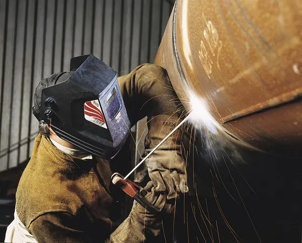
In Manual Metal Arc welding(MMA or MMAW) or Stick Welding uses an electrode which is flux coated and workpiece to create a arc. Both rod and surface material melt to create a weld.
Gas Shielded Metal Arc Welding(Metal Inert Gas(MIG))
It is an arc welding technique in which a consumable electrode is used to weld two metal sheet components together. MIG uses a consumable electrode, DC or AC Supply, Inert Gas Supply.
Shielding gas is used to prevent the weld pool from contamination. Contamination can affect the quality of weld. Shielding Gas also acts as a carrier of Filler Metal in the form of droplets. Shielding gases include 100% CO2 or a mixture of CO2 and Argon. A 75 percent Argon And 25 Percent combination of inert gas acts best for the visual quality of weld.
Gas Shielded Tungsten arc Welding(Tungsten Inert Gas(TIG)Welding)
TIG Welding also called GTAW uses a non consumable electrode to weld metals together. It is very similar to MIG welding. Weld area is protected by a shielding gas preferably Argon. It is called heliarc welding when helium is used as a shielding gas. This a complex process because it involves both the hands engagement as the filler rod is to be separately fed into the weld area and it is also slow compared to other welding techniques. Filler material depends on the nature of workpiece. Tungten has high melting temperature, hence, it remains unaffected during the welding process although some wear and tear can occur. TIG Welding can produce highest quality welds if done by a skilled welder. This welding technique became popular in 1940 as it could join magnesium and aluminum together.
2. Laser Beam Welding
Laser Beam Welding also called Conduction Welding or Radiation Welding is a highly precise welding technique. LASER is abbreviated as Light Amplification by Stimulated emission of Radiation. The beam provides a concentrated heat source, allowing for narrow, deep welds and high welding rates. Light is emitted in the form of bursts called pumps. These bursts of light are channeled along a seqm at the workpiece to be melted and welding is performed. It creates multiple welds at once. The pumps can be split and directed at different directions, which reduces the cost. Laser welding has application in the Automotive industry. The applications of laser in the manufacture of components cover engine parts, transmission parts, alternators, solenoids, fuel injectors, fuel filters, air conditioning equipment and air bags. In the comin years, it is a direct replacement for resistance spot welding or adhesive bonding, where lap joints or hem flange joints are utilised on pressed components for body-in-white assembly. Laser welding is also being applied in the production of partial penetration welds, for example, in hem flanges often used in doors, bonnets, boot lids and other closures.
3. Induction Welding
Induction Welding is a form of resistance welding in which there is no contact between the workpiece and the source. A coil is wrapped around the workpiece to be welded and a high radio frequency cureent is passed through it. The eddy currents produced in the workpiece cause the heating effect due to resistive heating. Plastic materials can also be induction welded by installing ferromagnetic or metallic conductors. Induction welding of carbon fiber reinforced plastics is commonly used in the aerospace industry. Induction welding is used for long production runs and is a highly automated process, usually used for welding the seams of pipes. It can be a very fast process, as a lot of power can be transferred to a localised area, so the faying surfaces melt very quickly and can be pressed together to form a continuous rolling weld.The depth that the currents, and therefore heating, penetrates from the surface is inversely proportional to the square root of the frequency. The temperature of the metals being welded and their composition will also affect the penetration depth. This process is very similar to resistance welding, except that in the case of resistance welding the current is delivered using contacts to the workpiece instead of using induction. This welding is used to make engine parts such as valves, crankshafts, camshafts, connection rods, starter rings and transmission parts, for example CV joints, tulips and axle shafts.
4. Oxy-Fuel Welding
In oxy fuel welding commonly called Gas Welding, a flame of gas is used to weld the metals together. The temperature of the tip of the flame reaches around 2500 celcius and 2500-3000 celcius at the inner core of the flame. In oxy-fuel welding, a welding torch is used to weld metals. Welding metal results when two pieces are heated to a temperature that produces a shared pool of molten metal. The molten pool is generally supplied with additional metal called filler. Filler material selection depends upon the metals to be welded. Oxy Fuel flame uses a mixture of oxygen and acetylene filled in the cylinders under pressure. Apart from acelylene, propane and methanol can also be used but Acetylene is most widely used gas. Before the invention of Arc welding, Gas welding was the only welding which was used to weld all kinds of materials like carbon steel, alloy steels, cast iron, aluminium, and magnesium.Oxy-acetylene welding is still used for metal-based artwork and in smaller home-based shops, as well as situations where accessing electricity. Although in many industrial operations, it has been superseded by Arc Welding due to its high speed and ability to weld highly reactive metals like titanium. It is used in Automotive Industry to weld parts of frame and chassis and is widely used in the Automotive repair works as thin to medium sheet metals are easily weld using gas welding.
5. Solid Reactant Welding
There are many elements and compounds which when react with each others under specific conditions or in presence of a catalyst produce enormous amount of heat. These reactions are called exothermic reactions. These compounds when channeled to the two metals can join them using the heat produced. The heat produced melts the two metals and these metals join together forming a strong bond on cooling. It requires no external source of heat or current. For exmple, Thermite is a compound made up of a metal oxide and Aluminium. The reactants are commonly powdered and mixed with a binder to keep the material solid and prevent separation. The weld quality of chemically pure thermite is low due to the low heat penetration into the joining metals and the very low carbon and alloy content in the nearly pure molten iron. To obtain sound railroad welds, the ends of the rails being thermite welded are preheated with a torch to an orange heat, to ensure the molten steel is not chilled during the pour. Solid reactant welding is widely used to weld railway rails.
5. 3-2-1 principle is used for the design of the fixtures
- For a fixture designer, the major portion of design time is spent deciding how to locate the workpiece in the fixture.
- You know that any free body has a total of twelve degrees of freedom as below:
6 translational degrees of freedom: +X, -X, +Y, -Y, +Z, -Z And
6 rotational degrees of freedom:
- Clockwise around X-axis (CROT-X)
- Anticlockwise around X-axis (ACROT-X)
- Clockwise around Y-axis (CROT-Y)
- Anticlockwise around Y-axis (ACROT-Y)
- Clockwise around Z-axis (CROT-Z)
- Anticlockwise around Z-axis (ACROT-Z)
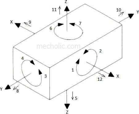
-
To make sure the proper fixing of the part we need to restrict all 12 degrees of freedom of the workpiece. The major portion of the time of BIW fixture designer is spent deciding how to fix these all DOF.
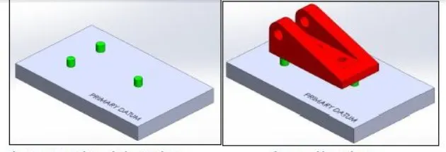
Primary locator
First, the three locators or supports are placed under the workpiece. It will be positioned on the primary locating surface also known as a datum. It will restrict 5 degrees of freedom.
- Axial Movement downward along Z-axis ( No.6 in Fig 1 )
- Rotation about the X & Y axis ( No. 7, 8, 9 & 10 in Fig 1)
Secondary locator
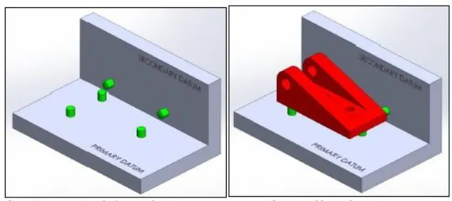
The next two locators are normally placed on the secondary surface, restricting an additional 3 degrees of freedom.
- Axial movement along the Y+ axis ( No.3 in Fig 1 )
- Rotation about the Z-axis ( No. 11 & 12 in Fig 1 )
Tertiary locator
This locator is positioned at the end of the part. It restricts 1 degree of freedom
- Axial movement along the X-axis ( No.2 in Fig 1)
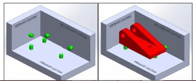
- All these 6 locators will restrict a total of 9 degrees of freedom. The remaining 3 degrees of freedom ( 1, 4 & 5 ) will be restricted by the clamps.
- To minimize the time consumption in assembly and disassembly, Have to use minimum numbers of pins to arrest a maximum number of degrees of freedom.
- The jig and fixture are tools used for holding the workpiece in a correct location for mass production. Various types of fixtures (like drilling fixtures, milling fixtures, and welding fixtures) are used in industry. The 3-2-1 method is the fundamental principle for all types of fixture design.
6. BODY COORDINATE SYSTEM (Part Locating System)
The body coordinate system has been widely used in the automotive industry for drawing of body parts, product & process design. A coordinate system is a reference system consisting of a set of points, lines & surfaces, used to define the positions of points in space in either two or three dimensions. In general BCS is also called as car line & body line.
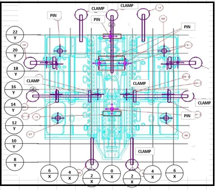
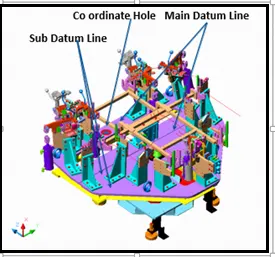
Car lines are the (grid lines) shown on the fixture, which virtually represent the same location in BIW. All the car line on fixture displays the coordinate at corner for reference. With these lines one can easily relate the location in BIW.
Sometimes single coordinate hole is given in fixture that also represents the car line coordinates, from that reference point fixture is made & can be inspected. Body coordinate are mentioned near hole. Below figure show car line on fixture.
Automotive sheet metal components are designed in CAD (Computer aided Design) software e.g. CATIAv4-v5, UG, ProE, Ideas,
In any cad tool, there is a default axis system X, Y, Z.
Lets us consider if every designer starts the design of the BIW Door Assembly part a default axis system, then it will be difficult to assembly or position the part with respect to each other.
Due to avoid this issue, BIW car panels are designed with reference to car axis means at their
Original position of the final car built.
Reference axis system of the software is used for the design of the various features of the parts (e.g. hole, fillet, threads,) To correlate the position of all the automotive components during the final assembly the axis system of the vehicle is used. Most of the time vehicle axis system and software axis system is the same. e.g. In most of European OEM, The X-axis represents the length of the vehicle Y-axis represents the width of the vehicle Z-axis presents the height of the vehicle. Y-axis is considered to be located at the front axle. All BIW welding fixtures are designed with reference to the car line
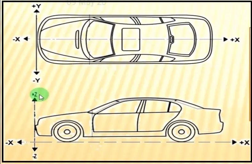
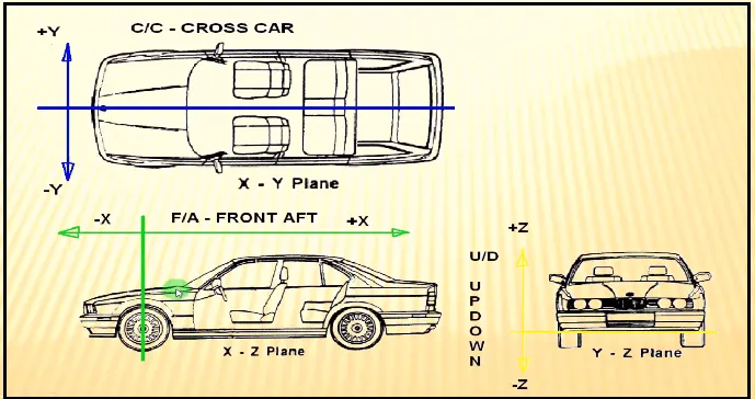
These datum schemes provide a reference system for all part surfaces and features using body coordinates. Figure below illustrates a typical body coordinate system. This system replaces the traditional X, Y, and Z directional designations with fore/aft (X), in/out (Y), and up/down or high/low (Z). The 0,0,0 point of the car is the front, lower, and center position.
Vehicle orientation : All vehicle product drawings are identified numerically relative to three vehicle planes described and shown below.
X= longitudinal direction (fore & after-F/A) or (Front O line-FOL).
Y= transverse direction (Cross car-C/C) or (Centre O line-COL).
Z= Vertical direction (Up & down- U/D) or (Bottom O Line-BOL).
The origin of the body coordinate system (OX) is defined at the front centre of a vehicle. It indicates a length of car & the coordinate system (OZ) is below its underbody indicates height of car & the coordinate system (OY) its starting point is the centre of car body indicates width of car.
Maintaining X,Y & Z coordinates in fixture is very important factor.
We should try that the coordinates of locating & clamping points should not be in three decimal (e.g. X=100.124, Y=245.127, Z=450.458)
They should be in the whole nos or max upto 1 decimal. Once these coordinate are maintained automatically the BIW base structure is mainteined.
7. Body plane system & its essentials.
Body planes are the reference plane in an automotive car. These planes are used to define the GD & T of all car parts in a automotive domain.
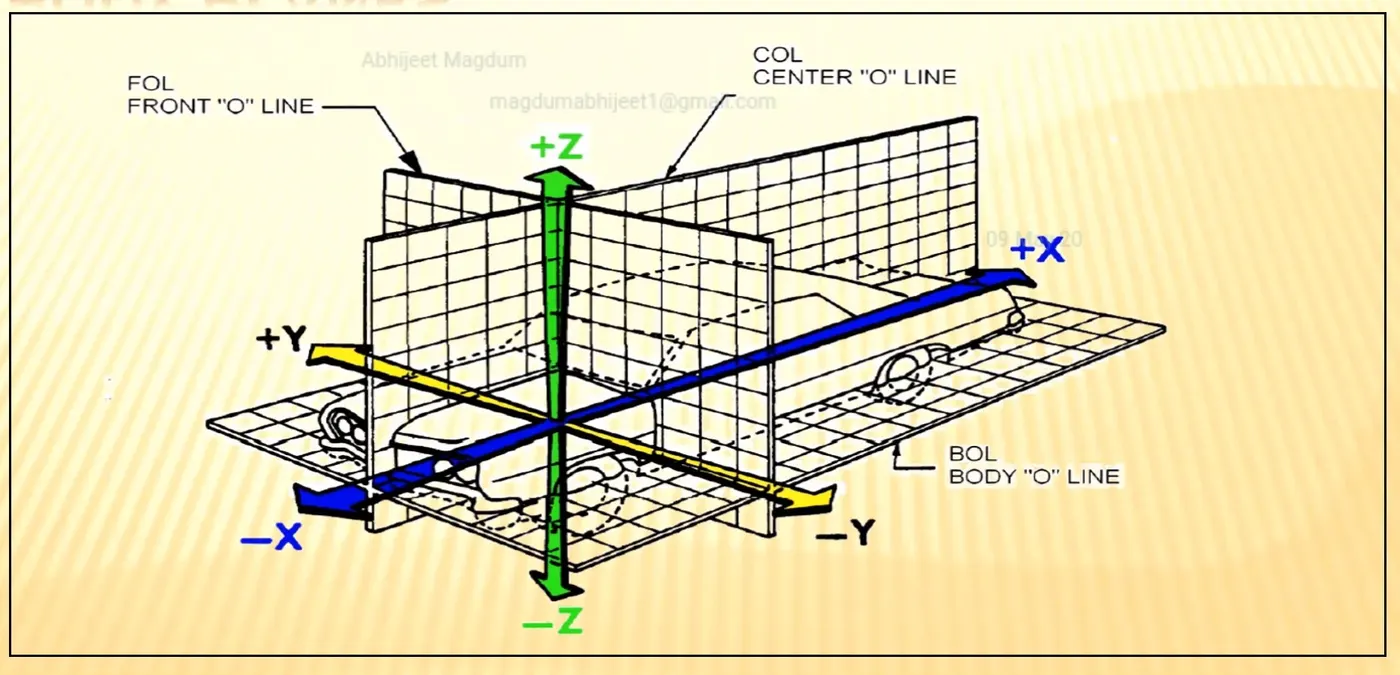
Body planes are three mutually perpendicular imaginary planes. These are generally considered to be present at the driver position or sometimes at the engine location or at the front end of the car depending on the customer.
The measurements from the body planes to the parts are called as body line dimension.
These body planes are called as
FOL Front “O” line.
COL Centre “O” line
BOL Body “O’ line
The measurement along FOL or X-axis is called as F/A Front aft.
The measurement along COL or Y-axis is called as C/C Cross car.
The measurement along BOL or Z-axis is called as U/DUP down.
In below figure origin is somewhere below driving sheet as it depends or changes from customer to customer. But axis system is commonly same.
Bodyline dimensions are essential for the reasons stated below,
- It defines the exact position of each product in the vehicle w.r.t. a fixed origin.
- It ensures flawless design for assembly.
- While designing lines, all the designs are carried out relative to the bodyline, viz, fixture, turn table etc.
- It assists in easy location of different parts in a vehicle.
- It aims in creating a standardized system.
- It assists in quality checks.
These are basic essential thing that body line dimension would help in BIW. It could help in designing lines like welding lines, assembly lines or car body through fixture & turntable etc. This help in designing every tools. Particular assembly or parts are designed w.r.t body lines or an axis system or car line also helps in quality while doing CMM of that system. CMM is basically done with the help of coordinate. It has relate particular fixture with that car part, because that dimension, coordinates of hole & pin should match so it will help in quality check also. We just give co-ordinates that belong to that hole both coordinate should match. With this matching means quality is approved. Below figure shows some example.
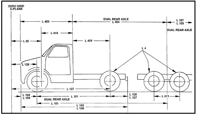
Below fig show use of X plane to define the length of car.
Below figure show use of Y plane to define width of car.
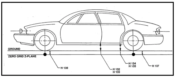
Below figure shows use of Z plane to define height of car.