Week 2:- BiW Fixture Basics Challenge
1. What is the process of project execution activity?
Project Activity:- It is a milestone, a section, or a task that has many sub-tasks under it. In simple words, any activity that requires several tasks to be completed to complete that activity is known as a project activity.
Below are the different stages of Project activities.
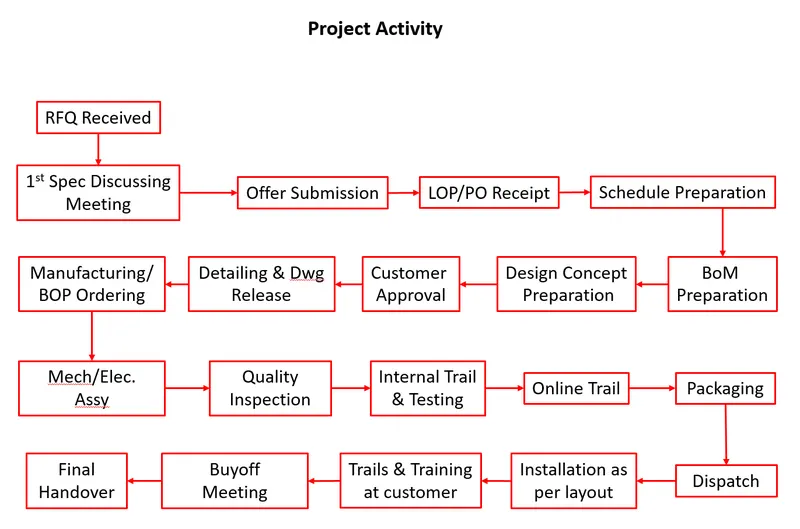
Fig 1:- Project Activity of Fixture Manufacturing
Request for Quote (RFQ):- The first and foremost step in the process of project execution activity is receiving a request for a quote from the customers with the requirements and specifications.
The RFQ contains the quantities and specifications of the product, which will be sent to various suppliers to figure out the best quote for the quantity they need.
RFQ is generally used by companies for large-scale procurement and used to solicit vendors and suppliers to narrow down choices for project bids.
1st Spec Discussion Meeting:- Upon receiving RFQ the Supplier Team huddles for a discussion to understand the voice of the customer and their requirements.
They start the benchmarking processes and validate their abilities to meet the customer requirements in the best possible way.
Offer Submission:- Based on the outcomes a detailed offer is proposed which contains details such as the Total Estimated cost of the project, Tentative Delivery timeline, Setting expectations of how project activities are executed, Customer -Supplier contract and guidelines, and request for further detailed information.
Thus the Offer is very detailed and unique to potentially grab the attraction of the customer and to differentiate from its competitors.
OI/PO Receipt:- A successful Project proposal will receive a Letter of Invitation or Purchase Order receipt. Thus this embarks the Project kick-off and the supplier starts to prepare a Project Schedule. In this phase, Technical details of the parts to be manufactured are also received.
Project Schedule:- Project Management tools such as CPM, Gantt chart, or software such as Primavera, and Windchill are used to schedule detailed project activities for the timeline. A detailed schedule is essential to track the project activities and to achieve critical milestones like Design, BOM Preparation, Raw Material Purchase, Production, Quality Checking, Installation, etc. and would lead to the successful completion of the Project on time.
BOM Preparation:- Based on the LOI Review meeting the parts for the fixtures are categorized and a detailed Bill of Materials is prepared.
Design Concept Preparation:- With BOM being prepared concept sketch is developed through Ideation and carry-over study to develop the base, pin, stand, and clamp units. This will follow all the specifications and guidelines defined by the client.
Customer Approval Stage:- The prepared concept will be sent to the customer to validate all details and for approval. Any changes or modifications will be notified by the client and subsequent changes are made.
Detailing & Design Stage:- After the approval from the customer, the fixtures design process and detailing will start. All the parts to be produced are designed in the CAD software. The concept will be validated through simulation software and then a Manufacturing BOM is prepared.
Manufacturing/BOP ordering:- The BOM will be cross-checked by the Quality Team to verify the process and then the Manufacturing Team will start procurement of parts for manufacturing. The development stage will carry out the feasibility report to analyze whether the design is manufacturable and based on the DFM reports. The Production phase will start after conformance with Quality Team and Design Team.
Mechanical/Electrical Assembly:- The Next stage of Fixture Design is Assembly. A detailed Assembly procedure is developed and the parts are assembled and mounted for inspection.
Quality Inspection:- The Quality inspection stage will verify all the units using CMM and other inspection devices and the quality report generated through CMM will be compared with the initial drawing release. After approval from the Quality team, a physical simulation environment is set up to do a trial-and run
Internal trial & testing:- The internal trial and testing team will check the functions of the various fixtures like clamping and also measure the tolerance deviation and relative dimension between the mating parts. The initial trial and test will validate the fixture and material handling techniques and the parts will pass the Quality Check.
Online trial:- Online Trial stage is where all the automation functions of the fixtures are tested to check the efficiency of sensors in clamp opening and closing and the movement of the Clamp Handles and various movements. The Reed switch and sensor movement is validated. Once the fixtures reach the quality benchmark level the testing and inspection are completed and parts are transferred for packaging
Packaging & Dispatch:- The manufactured fixtures after completing the production trials and online trials, is sent for packaging and dispatch. The number of parts involved and the layout of the assembly are transcended to the customers with the shipment details and Expected Delivery Date.
Installation as per layout:- The dispatched parts are verified to the supplier evaluation procedure to verify the quantity of the parts and the customer/client team will verify with the LOI after approval the fixtures are assembled as per the layout and the Fixture assembly is ready for another trail at customer end
Training & Trials at Customer:- In this stage, the client workforce is trained about the fixture and how to operate in a simulated work environment. The efficiency and function of the fixtures are demonstrated at the customer end.
Buy-off meeting:- The Buy off meeting is done to get the feedback of the customer and any modifications mentioned will be sought and any additional requirements prescribed will involve additional quotation. The service and warranty options of the fixture will also be discussed and the after-sales team will create suitable documents for Service Engineers and a Service Level Agreement is signed.
Final Handover:- After completing all the stages the Fixtures are handed over to the customer.
2. What are the types of joining processes?
Metal Joining is defined as the joining of two material parts either temporarily or permanently with or without the application of heat or pressure.
Generally, these joining techniques are divided into two main categories, i.e
1. Mechanical Joining:- Mechanical joining includes bolting, riveting, caulking, shrink fitting, and folding, all of which join workpieces by using mechanical energy.
2. Metallurgical Joining:- Metallurgical joining includes fusion welding, pressure welding, and brazing/soldering which use different energies.
3. Chemical Joining:- There are also methods of chemical joining that use adhesives.
Every joining method has advantages and disadvantages. To ensure efficient joining, you need to select the right method according to the materials and joining conditions.
1. Mechanical Joining
- Riveting:- Riveting is a semi-permanent and non-thermal joining method that involves using a mechanical fastener/rivet (a metallic part with a dome-shaped head) to join sheet metal parts.
Riveting involves drilling a hole in the two sheet metal parts you want to join together and installing a rivet.
Fig 2:- Rivet Joint
- Caulking:- Caulking is a process employed on riveted joints of pressure vessels like tanks, and steam boilers to make joints leakproof and fluid-tight.
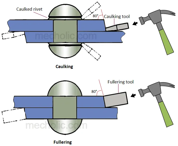
Fig 3:- Caulk Joint
- Bolting:- A bolted joint is one of the most common elements in construction and machine design. It consists of a male-threaded fastener that captures and joins other parts, secured with a matching female screw thread.
Fig 4:- Bolt's joint
- Shrink fitting:- Shrink fitting refers broadly to techniques in which thermal expansion and contraction effects are used to achieve an interference fit. Commonly, this involves the heating of the 'outer' part so that it undergoes thermal expansion. The two pieces can then be relatively easily fitted together.
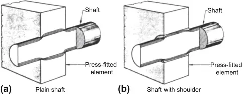
Fig 5:- Shrink Fitting
- Folding:- Sheet metal parts can be connected by folding or bending tabs in the form of a buckle and a clamping slot.
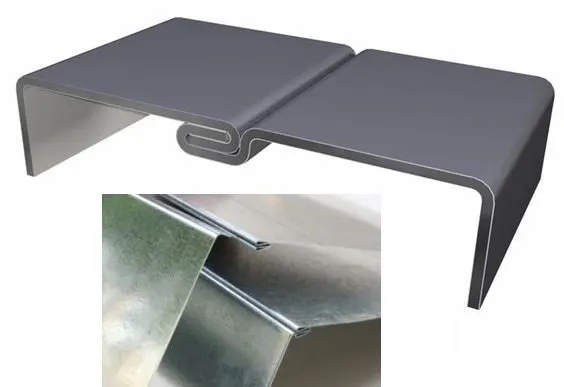
Fig 6:- Folding Joint
2. Metallurgical Joining
Metallurgical joining includes fusion welding, pressure welding, and brazing/soldering which use different energies. Below are the well know metallurgical Joining methods.
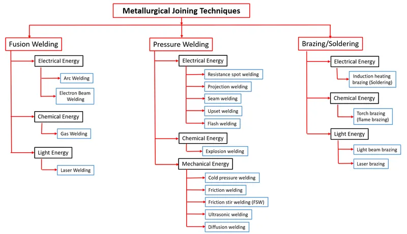
Fig 7:- Metallurgical Joining Techniques
A. Fusion Welding:- Fusion welding is a process that uses heat to join or fuse two or more materials by heating them to the melting point. The process may or may not require the use of a filler material. External application of pressure is not required for fusion welding processes, except for resistance welding, where substantial contact pressure is required during welding for sound joining.
a. Arc Welding:- Arc welding is one of many fusion welding processes used to join metals. It uses an electric arc to create intense heat to melt and join metals. A power source generates an electric arc between a consumable or non-consumable electrode and base metal. Arc welders can use either direct current (DC) or alternating current (AC).
Process:- Arc welding is a fusion welding process used to join metals. An electric arc from an AC or DC power supply creates an intense heat of around 6500°F which melts the metal at the joint between two work pieces.
Fig 8:- Arc Welding
The arc can be either manually or mechanically guided along the line of the join, while the electrode either simply carries the current or conducts the current and melts into the weld pool at the same time to supply filler metal to the joint.
Because the metals react chemically to oxygen and nitrogen in the air when heated to high temperatures by the arc, a protective shielding gas or slag is used to minimize the contact of the molten metal with the air. Once cooled, the molten metals solidify to form a metallurgical bond.
Below are the types of Arc welding.
- Shielded Metal Arc Welding (Stick Welding)
- Gas Metal Arc Welding (MIG or MAG Welding)
- Flux-Cored Arc Welding
- Gas Tungsten Arc Welding (TIG Welding)
- Plasma Arc Welding
- Carbon Arc Welding
- Submerged Arc Welding
- Atomic Hydrogen Welding
- Electroslag Welding
- Drawn Arc (DA) Stud Welding
b. Electron Beam Welding:- Electron beam welding (EBW) is a welding process in which a beam of high-velocity electrons is applied to the materials being joined or fused. When these high-velocity electrons impact the workpieces, the kinetic energy of the electrons is transformed into heat, which melts the workpieces.
Working Principle of Electron Beam Welding
A typical schematic of the electron beam welding (electron beam gun) is shown in the figure below.
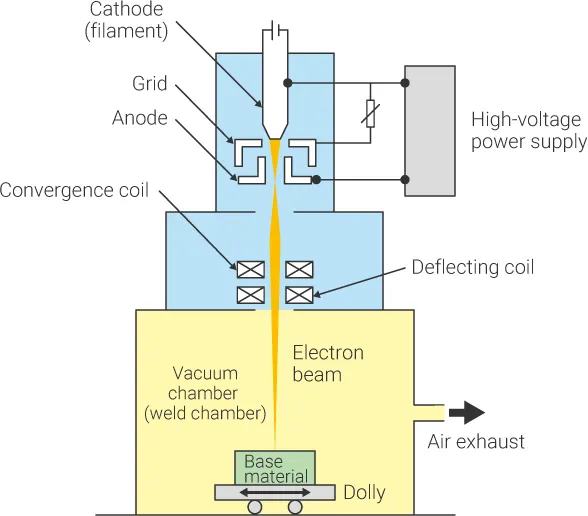
Fig 9:- Electron Beam Welding
In electron beam welding, when a cathode in a vacuum is heated by a filament, it emits a beam of high-velocity electrons. These electrons are further accelerated by voltage and are converged by an electromagnetic coil. When the electron beam strikes the workpiece, the kinetic energy of the electrons is converted into heat. This heat energy generated is then utilized for the welding process.
For a typical electron beam welding machine, the diameter of the beam spot is about 0.2 mm. The electron beam welding allows less distortion, as the heat applied to the area around the weld is low.
c. Laser Welding:- Laser Beam Welding is a fusion welding process in which two metal pieces are joined together by the use of a laser. The laser beams are focused on the cavity between the two metal pieces to be joined. The laser beams have enough energy and when it strikes the metal pieces produce heat that melts the material from the two metal pieces and fills the cavity. After cooling a strong weld is formed between the two pieces.
Working Principle
It works on the principle that when electrons of an atom get excited by absorbing some energy. And then after some time when it returns to its ground state, it emits a photon of light. The concentration of this emitted photon is increased by stimulated emission of radiation and we get a high energy concentrated laser beam.
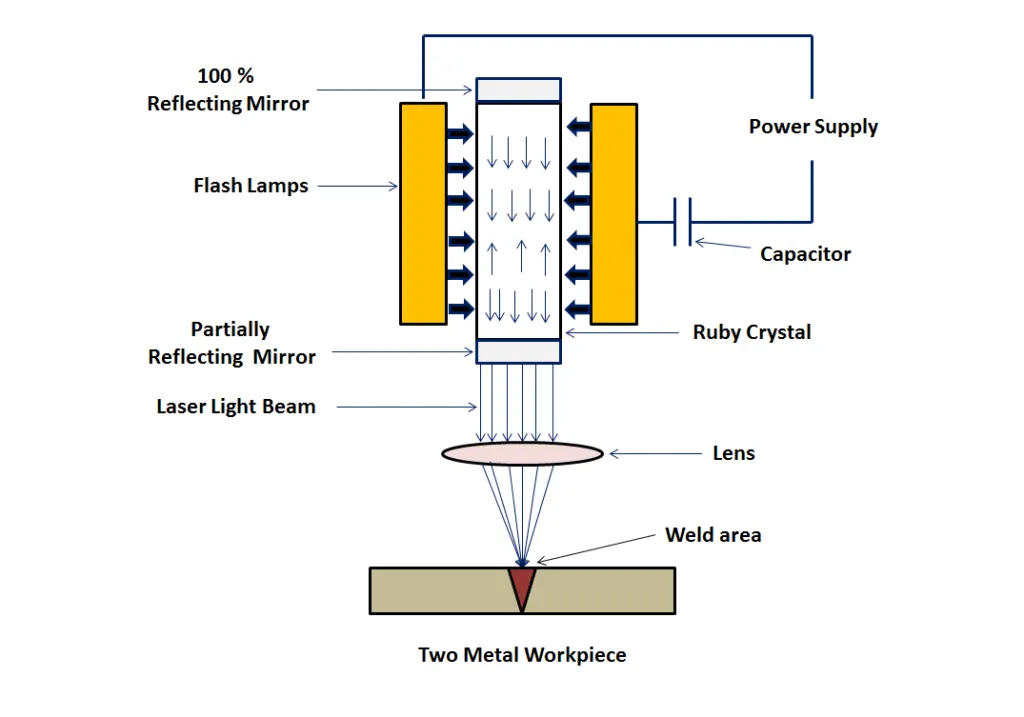
Fig 10:- Laser Beam Welding
First, the setup of the welding machine at the desired location (in between the two metal pieces to be joined) is done.
After setup, a high-voltage power supply is applied to the laser machine. This starts the flash lamps of the machine and it emits light photons. The energy of the light photon is absorbed by the atoms of the ruby crystal and electrons get excited to their higher energy level. When they return to their ground state (lower Energy state) they emit a photon of light. This light photon again stimulates the excited electrons of the atom and produces two photons. This process keeps continue and we get a concentrated laser beam.
This highly concentrated laser beam is focused on the desired location for the welding of the multiple pieces together. The lens is used to focus the laser on the area where welding is needed. CAM is used to control the motion of the laser and workpiece table during the welding process.
As the laser beam strikes the cavity between the two metal pieces to be joined, it melts the base metal from both pieces and fuses them. After solidification, we get a strong weld.
This is how laser Beam Welding Works.
B. Pressure Welding:- Pressure welding uses friction or explosion to heat the joining section of metal workpieces and join them under pressure. The process is also called solid-state welding. Pressure welding is a generic term for welding methods that weld workpieces by applying mechanical pressure on the joining section (weld joint).
Below are the types of Pressure welding.
- Resistance spot welding
- Projection welding
- Seam welding
- Upset welding
- Flash welding
- Explosion welding
- Cold pressure welding
- Friction welding
- Friction stir welding (FSW)
- Ultrasonic welding
- Diffusion welding
a. Resistance spot welding:- Spot welding (also known as resistance spot welding) is a resistance welding process. This welding process is used primarily for welding two or more metal sheets together by applying pressure and heat from an electric current to the weld area.
It works by contacting copper alloy electrodes to the sheet surfaces, whereby pressure and electric current are applied and heat is generated by the passage of current through resistive materials such as low-carbon steels.
A form of resistance welding, spot welding is one of the oldest welding processes whereby two or more sheets of metal are welded together without the use of any filler material.
The process involves applying pressure and heat to the weld area using shaped alloy copper electrodes which convey an electrical current through the weld pieces. The material melts, fusing the parts at which point the current is turned off, pressure from the electrodes is maintained and the molten “nugget” solidifies to form the joint.
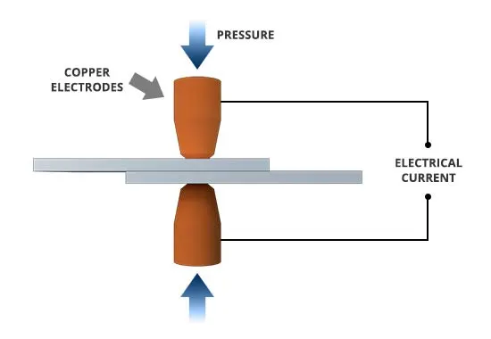
Fig 11:- Resistance spot welding
The welding heat is generated by the electric current, which is transferred to the workpiece through copper alloy electrodes. Copper is used for the electrodes as it has high thermal conductivity and low electrical resistance compared to most other metals, ensuring that the heat is generated preferentially in the workpieces rather than the electrodes.
b. Projection welding:- Like other Resistance Welding Processes, Projection Welding uses heat generated by resistance to the flow of welding current, as well as force to push the workpieces together, applied over a defined period. Projection Welding localizes the welds at predetermined points by using projections, embossments, or intersections, all of which focus on heat generation at the point of contact. Once the weld current generates sufficient resistance at the point of contact, the projections collapse, forming the weld nugget.
Solid Projections are often used when welding fasteners to parts. Embossments are often used when joining sheet or plate material. An example of Projection Welding using material Intersections is cross-wire welding. In this case, the intersection of the wires themselves localizes heat generation, and therefore resistance. The wires set down into one another, forming a weld nugget in the process.
c. Seam Welding:- Resistance Seam Welding is a subset of Resistance Spot Welding using wheel-shaped electrodes to deliver force and welding current to the parts. The difference is that the workpiece rolls between the wheel-shaped electrodes while weld current is applied. Depending on the particular weld current and weld time settings, the welds created may be overlapping, forming a complete welded seam, or may simply be individual spot welds at defined intervals.
d. Flash Welding:- Like other Resistance Welding Processes, Flash Welding uses heat generated by resistance to the flow of welding current, as well as force to push the workpieces together, applied over a defined period. Flash Welding is a Resistance Welding Process that generates resistance using flashing action. This action is created using very high current density at very small contact points between the workpieces. At a predetermined point after the flashing process has begun, force is applied to the workpiece, and they are moved together at a controlled rate. Rapid upset created by this force expels oxides and impurities from the weld.
e. Upset Welding:- Like other Resistance Welding Processes, Upset Welding uses heat generated by resistance to the flow of welding current, as well as force to push the workpieces together, applied over a defined period. While similar to Flash Welding, in Upset Welding the workpieces are already in firm contact with one another, so no flashing occurs. Pressure is applied before the current is started, and is maintained until the process is complete.
f. Explosion welding:- The explosive welding technique has found major use for cladding low-cost plates (usually carbon steel) with more expensive corrosion-resistant materials. This clad plate is typically used in the chemical and petrochemical industries as a tube sheet for heat exchangers.
Explosive welding differs from other traditional joining processes as it does not depend on the melting of two metals to be joined, or on plastic deformation of the surfaces in contact as occurs with cold or hot pressure welding. In simple terms, an explosive weld is achieved by impelling the cladding plate against the substrate plate material using the considerable energy from an explosive discharge, resulting in a high energy rate impact. The high interfacial pressure at the point of contact (or collision front) between the cladding plate and the substrate plate must be greater than the yield strength of both materials, to permit plastic deformation within the surface layers to occur. A jet of highly softened metal is formed at the collision front and is projected in front of it as it progresses rapidly across the weld interface. As the jet progresses, it thoroughly cleans the surfaces, thus permitting solid phase bonding to occur between the two materials.
Fig 12:- Explosion welding
Because bonding occurs in the solid phase, it is possible to weld metals with different melting points and some of the common clad layers deposited onto steel plates are aluminum, copper, bronze, titanium, Monel, nickel alloys, and zirconium. Alternatively, explosive welding can be used to repair or plug tubes in heat exchangers on-site, where conventional welding methods are difficult to use.
g. Cold pressure welding:- Cold welding, also known as cold pressure welding or contact welding, is a solid-state welding process where the joining of two metals takes place without fusion or heating at the interface of the two parts being welded together. This means there is no liquid or molten phase present in the joint and joining process.
Procedure:- The process of cold welding works by using pressure to join two metals or materials. Generally speaking, when two metals are pressed together they don’t weld to each other. This is mainly due to there being an oxide layer or thin barrier on the surface of the two materials which prevents them from diffusing together.
Fig 13:- Cold Pressure welding
However, cold welding overcomes this by preparing the metals beforehand. This preparation involves cleaning and brushing the metals to such a high degree that this top barrier or oxide layer is removed.
Through degreasing and wire brushing the metal before the welding takes place, it enables a desirable clean surface in which the metals can be pressed together with the right amount of force and thus welded together.
Cold welding material tips: the materials must not have undergone severe hardening and must be ductile. Soft metals are often the best choices for cold welding.
h. Friction Welding:- Friction welding, as the name implies, uses friction to weld joints. There is no external heat that is applied in the joining process.
Hence, friction welding is not a fusion weld process but a solid-state weld process where the resultant joint is often as strong as the parent metal. This welding technique is employed in several industries to join parts.
The process of friction welding
If you rub your palms against each other, you’ll observe that your palms will become hot. As you increase the pressure and speed further, you will start feeling warmer.
The same principle of heat generation by friction is used in friction welding, where the metal parts are made to rub against each other at extremely high speed and pressure.
This interaction between the two surfaces results in mechanical friction. Even if the two materials to be welded together may seem smooth to the naked eye, there are irregularities at the microscopic level. These irregularities are enough to generate friction between their surfaces.
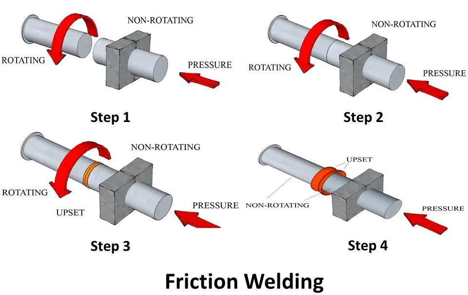
Fig 14:- Friction welding
When two materials undergo friction welding, the relative motion between each other, and the pressure applied to them generates heat at the contact points. As the process continues further, the heat generation also rises, and the two materials will start becoming viscous at the contact points.
Again, the motion between the two promotes the mixing of the two parts at their contact points, creating a bond or a weld.
i. Friction stir welding (FSW):- Friction stir welding is the optimal joining process for non-ferrous metals with a low melting temperature and for mixed-metal combinations.
Friction stir welding (FSW): the process
Friction stir welding is a process in which a rotating pin is traversed along the contact surfaces between the workpieces. The frictional heat plasticizes the material, which is welded together.
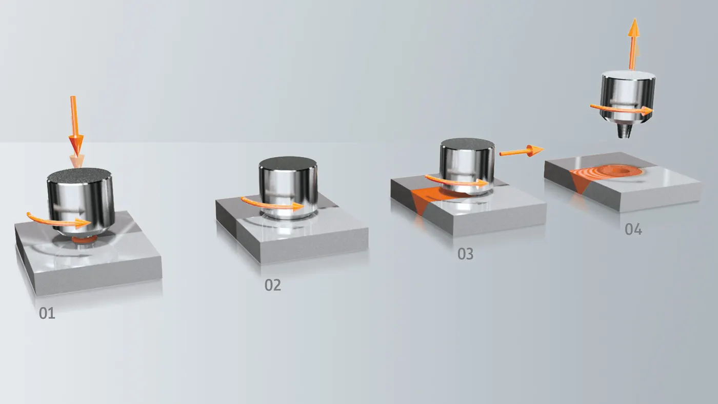
Fig 15:- Friction Stir welding
The FSW process is particularly suitable for joining non-ferrous metals with a low melting temperature and for mixed-material joints. Even materials that are difficult to weld or dissimilar materials such as aluminum with magnesium, copper, or steel can be friction stir welded.
j. Ultrasonic welding:- Ultrasonic welding (USW) is a solid-state welding process that produces a weld by local application of high-frequency vibratory energy while the workpieces are held together under pressure. A sound metallurgical bond is produced without melting the base material.
Principle:- It works on the basic principle of energy of ultrasonic waves. Ultrasonic vibration creates dynamic shear stress between the contacts of two workpieces. Due to local plastic deformation and heat generate due to friction between contact surfaces, joint formation will take place at the interface.
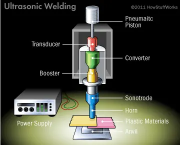
Fig 16:- Ultrasonic welding
Working:- This welding works as follows.
- At the start, high-frequency current passes through a piezoelectric transducer. This transducer converts high-frequency electrical signals into mechanical vibration.
- This vibration is further supplied to the booster which amplifies its frequency.
- The amplified high-frequency vibration passes through the horn which is in contact with the welding plate.
- This welding creates a lap joint. One plant of the weld is fixed into the fixture and the other one is in direct contact with the horn. These plates are fixed under moderate pressure force.
- The horn supplies high-frequency mechanical vibration to the welding plate.
- Due to this vibration, oscillation shear force act at the interface between welding plates which results in elastoplastic deformation at the interface.
- It also creates a localized temperature rise due to mechanical force and friction. This heat helps in plastic deformation at the interface and makes a strong joint without melting the workpiece or using filler metal.
k. Diffusion welding:- Diffusion bonding or diffusion welding is a solid-state welding technique used in metalworking, capable of joining similar and dissimilar metals. It operates on the principle of solid-state diffusion, wherein the atoms of two solid, metallic surfaces intersperse themselves over time. This is typically accomplished at an elevated temperature, approximately 50-75% of the absolute melting temperature of the materials. Diffusion bonding is usually implemented by applying high pressure, in conjunction with necessarily high temperature, to the materials to be welded; the technique is most commonly used to weld "sandwiches" of alternating layers of thin metal foil, and metal wires or filaments. Currently, the diffusion bonding method is widely used in the joining of high-strength and refractory metals within the aerospace and nuclear industries.
Fig 17:- Diffusion welding
C. Brazing/Soldering
Brazing:- Brazing joins metal surfaces together with a filler metal that has a low melting point. The process uses capillary action wherein the homogenous liquid flow of the filler material bonds with the base metals.
A unique quality in the brazing process is that it keeps the mechanical properties of the metals which are useful in applications such as silver brazing or other similar metals.
Brazing Process:- One of the most crucial steps in the metal joining process is the cleaning of the base metal surfaces. Emery cloth or wire brush are both great tools to remove contaminants.
Fig 17:- Brazing
Having calculated joint gaps for the liquid filler metal to achieve surface tension with the workpiece, the brazing operation begins with properly positioning the assembly. A torch is normally used to slowly heat the workpiece’s metal surface and filler metal into its brazing temperature.
Soldering:- Soldering is a joining process used to join different types of metals together by melting solder. Solder is a metal alloy usually made of tin and lead which is melted using a hot iron. The iron is heated to temperatures above 600 degrees Fahrenheit which then cools to create a strong electrical bond.
The soldier is melted by using heat from an iron connected to a temperature controller. It is heated up to temperatures beyond its melting point at around 600 degrees Fahrenheit which then causes it to melt, which then cools creating the soldered joint.
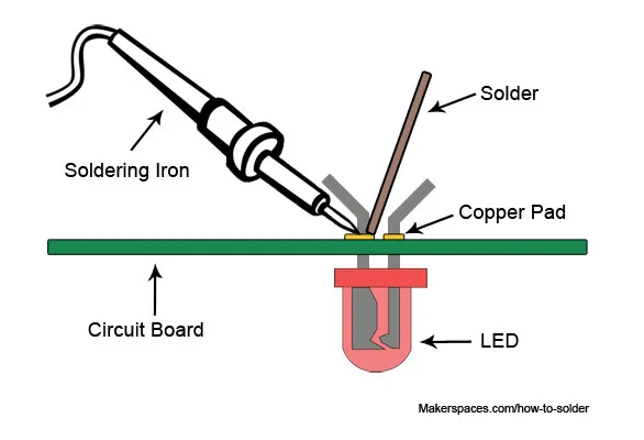
Fig 17:- Soldering
As well as creating strong electrical joints solder can also be removed using a desoldering tool.
Solder is a metal alloy used to create strong permanent bonds; such as copper joining in circuit boards and copper pipe joints. It can also be supplied in two different types and diameters, lead and lead-free, and also can be between .032” and .062”. Inside the solder core is the flux, a material used to strengthen and improve its mechanical properties.
3. What is Resistance Welding & its application in the automotive sector?
Resistance welding:- Resistance welding can be defined as; it is a liquid-state welding method where the metal-to-metal joint can be formed within a liquid state or otherwise molten state. This is a thermoelectric method where heat can be generated at the It is a thermo-electric process in which heat is generated at the edge planes of welding plates because of electric resistance and a weld joint can be created by applying low-pressure to these plates. This type of welding uses electric resistance to generate heat. This process is very efficient with pollution free but the applications are limited because of the features like equipment cost is high, and material thickness is limited.
Resistance Welding Working Principle
The working principle of resistance welding is the generation of heat because of electric resistance. Resistance welding such as seam, spot, and protection works on the same principle. Whenever the current flows through electric resistance, then heat will be generated. The same working principle can be used within the electric coil. The generated heat will depend on the material’s resistance, applied current, conditions of a surface, applied the current period
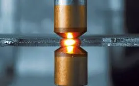
Fig 18:- Resistance Welding
This heat generation takes place because of the energy conversion from electric to thermal. The resistance welding formula for heat generation is
H = I2RT
Where
‘H’ is a generated Heat, and the unit of heat is a joule
‘I’ is an electric current, and the unit of this is ampere
‘R’ is an electric resistance, and the unit of this is Ohm
‘T’ is the time of current flow, and the unit of this is second
The generated heat can be used to soften the edge metal to shape a tough weld joint with fusion. This method generates weld with no application of any flux, filler material, or shielding gases.
Types of Resistance Welding
Different types of resistance welding are discussed below.
Spot Welding
Spot welding is the simplest type of welding where the work portions are held jointly below the force of the anvil face. The copper (Cu) electrodes will make contact with the work portion & the flow of current through it. The work portion material applies a few resistances within the current flow which will cause limited heat production. The resistance is high at the edge surfaces because of the air gap. The current begins to supply through it, then it will reduce the edge surface.
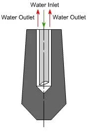
Fig 19:- Spot Welding
The current supply & the time must be enough for the correct dissolving of edge faces. Now the flow of current will be stopped however the force applied with the electrode continued for a second, whereas the weld quickly cooled. Later, the electrodes eliminate as well as get in touch with a new spot to create a circular piece. The piece size mainly depends on electrode size (4-7 mm).
Seam Welding
This type of welding is also known as continuous spot welding where a roller-form electrode can be utilized to supply current throughout work parts. Initially, the roller electrodes are getting in touch with the work part. High current can be supplied through these electrode rollers to melt the edge surfaces & shape a weld joint.
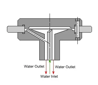
Fig 20:- Seam Welding
At present, the electrode rollers will begin rolling on work plates to make a permanent weld joint. The weld timing & electrode movement can be controlled to guarantee that the weld overlap & work part doesn’t acquire too warm. The speed of the welding can be about 60 in per min within seam welding, which is used to make airtight joints.
Projection Welding
Projection welding is similar to spot welding apart from a dimple that can be generated on work parts at the place wherever weld is preferred. At present the work parts held among electrodes as well as a huge quantity of current flows through it. A little quantity of pressure can be applied throughout the electrode on welding shields. The flow of current throughout the dimple dissolves it & the force reasons the dimple to level & shape a weld.
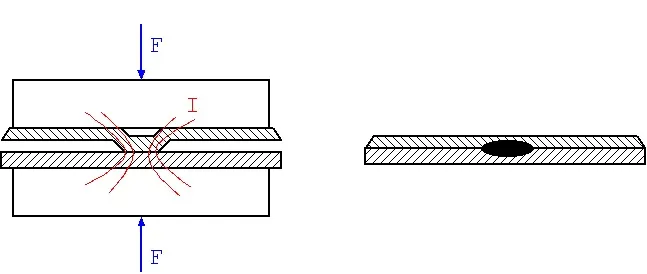
Fig 21:- Projection Welding
Flash butt Welding
Flash butt welding is a form of resistance welding, used for welding tubes as well as rods within steel industries. In this method, two work parts are welded which will be held tightly during the electrode holders as well as a high pulsed flow of current within the 1,00,000 ampere range can be supplied toward the work part material.
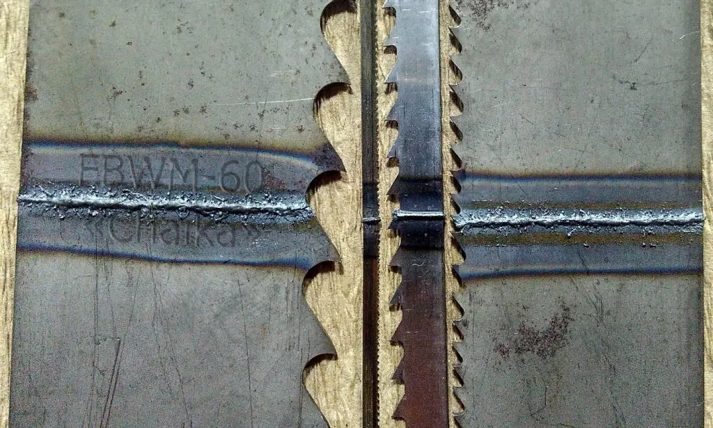
Fig 22:- Flash butt Welding
In the two electrode holders, one is permanent & other is changeable. At first, the flow of current can be supplied & changeable clamp will be forced against the permanent clamp because of the get in touch with the two work parts at high current, and the spark will be generated. Whenever the edge surface approaches a plastic shape, the flow of current will be stopped as well as axial force can be improved to create a joint. In this method, the weld can be formed because of plastic deformation.
Resistance Welding Applications
The applications of resistance welding include the following.
- This type of welding can be widely used within automotive industries, making nuts as well as a bolt.
- Seam welding can be utilized to generate leak-prove joints necessary within little tanks, boilers, etc.
- Flash welding can be used for welding tubes and pipes.
- Resistance Welding Advantages and Disadvantages
- The advantages & disadvantages of resistance welding include the following
Advantages
- This method is simple and does not necessarily high expert labor.
- The resistance welding metal thickness is 20mm, & thinness is 0.1 mm
- Automated simply
- The rate of production is high
- Both related, & different metals can be welded.
- Welding speed will be high
- It does not need any flux, filler metal & protecting gases.
Disadvantages
- Tools cost will be high.
- The work section thickness is limited because of the current requirement.
- It is less proficient for high-conductive equipment.
- It consumes high electric power.
- Weld's joints contain small tensile & fatigue power.
Resistance welding Applications in the Automotive sector
To reduce vehicle mass, automakers are incorporating lightweight materials within vehicle bodies at an ever-increasing rate. The primary focus has been on incorporating ultra-high strength steels such as press-hardened steels, complex phase steels, and others. Even further mass reductions can be achieved by incorporating aluminum alloy materials such as sheets, extrusions, and castings into a multi-material body. These lightweight materials must be joined to form automotive body structures in such a way as to reduce mass, yet the ideal joint is a compromise between robust performance and an easily implemented production solution that is low-cost and high quality.
Fig 23:- Resistance welding
Typical body structure assembly plants are based upon resistance spot welding technology as it is flexible, low-cost, fast, and can be applied to both aluminum-aluminum and steel-steel joints. However, resistance spot welding offers several interesting metallurgical challenges that must be addressed to form robust joints as advanced material alloys and combinations such as aluminum steel are introduced. An introduction to joining in the automotive industry will be given with special emphasis on the metallurgy of resistance spot welding and the aluminum-steel spot welding process. Case studies will be presented that describe the static and dynamic mechanical performance of the dissimilar aluminum-steel welds and their robustness to production conditions such as gaps between sheets, electrodes off normal (at an angle) to the metal sheets, and changes in current.
4. What is fusion welding & types of fusion welding with its application in the automotive sector?
Fusion Welding:- Fusion welding is a process that uses heat to join or fuse two or more materials by heating them to the melting point. The process may or may not require the use of a filler material. External application of pressure is not required for fusion welding processes, except for resistance welding, where substantial contact pressure is required during welding for sound joining.
a. Arc Welding:- Arc welding is one of many fusion welding processes used to join metals. It uses an electric arc to create intense heat to melt and join metals. A power source generates an electric arc between a consumable or non-consumable electrode and base metal. Arc welders can use either direct current (DC) or alternating current (AC).
Process:- Arc welding is a fusion welding process used to join metals. An electric arc from an AC or DC power supply creates an intense heat of around 6500°F which melts the metal at the joint between two work pieces.
Fig 24:- Arc welding
The arc can be either manually or mechanically guided along the line of the join, while the electrode either simply carries the current or conducts the current and melts into the weld pool at the same time to supply filler metal to the joint.
Because the metals react chemically to oxygen and nitrogen in the air when heated to high temperatures by the arc, a protective shielding gas or slag is used to minimize the contact of the molten metal with the air. Once cooled, the molten metals solidify to form a metallurgical bond.
Below are the types of Arc welding.
- Shielded Metal Arc Welding (Stick Welding)
- Gas Metal Arc Welding (MIG or MAG Welding)
- Flux-Cored Arc Welding
- Gas Tungsten Arc Welding (TIG Welding)
- Plasma Arc Welding
- Carbon Arc Welding
- Submerged Arc Welding
- Atomic Hydrogen Welding
- Electroslag Welding
- Drawn Arc (DA) Stud Welding
Shielded Metal Arc Welding (SMAW):-
Shielded metal arc welding (Stick welding, Manual metal arc welding) uses a metallic consumable electrode of a proper composition for generating an arc between itself and the parent workpiece. The molten electrode metal fills the weld gap and joins the workpieces.
This is the most popular welding process capable to produce a great variety of welds.
Fig 25:- Shielded Metal Arc Welding
The electrodes are coated with a shielding flux of suitable composition. The flux melts together with the electrode metallic core, forming a gas and a slag, shielding the arc and the weld pool. The flux cleans the metal surface, supplies some alloying elements to the weld, protects the molten metal from oxidation, and stabilizes the arc.
The slag is removed after Solidification.
Advantages of Shielded Metal Arc Welding (SMAW):
- Simple, portable, and inexpensive equipment;
- Wide variety of metals, welding positions, and electrodes are applicable;
- Suitable for outdoor applications.
Disadvantages of Shielded Metal Arc Welding (SMAW):
- The process is discontinuous due to the limited length of the electrodes;
- Weld may contain slag inclusions;
- Fumes make difficult process control.
Gas Metal Arc Welding:- Metal Inert Gas Welding (Gas Metal Arc Welding) is an arc welding process, in which the weld is shielded by an external gas (Argon, helium, CO2, argon + Oxygen, or other gas mixtures).
Consumable electrode wire, having a chemical composition similar to that of the parent material, is continuously fed from a spool to the arc zone. The arc heats and melts both the workpiece’s edges and the electrode wire. The fused electrode material is supplied to the surfaces of the workpieces fills the weld pool and forms joints.
Fig 26:- Metal Inert Gas Welding
Due to the automatic feeding of the filling wire (electrode), the process is referred to as semi-automatic. The operator controls only the torch positioning and speed.
Advantages of Metal Inert Gas Welding (MIG, GMAW):
- The continuous weld may be produced (no interruptions).
- A high level of operator skill is not required.
- Slag removal is not required (no slag).
Disadvantages of Metal Inert Gas Welding (MIG, GMAW):
- Expensive and non-portable equipment is required.
- Outdoor applications are limited because of the effect of wind, dispersing the shielding gas.
Gas Tungsten Arc Welding:- Tungsten Inert Gas Arc Welding (Gas Tungsten Arc Welding) is a welding process, in which heat is generated by an electric arc struck between a tungsten non-consumable electrode and the workpiece.
The weld pool is shielded by an inert gas (Argon, helium, Nitrogen) protecting the molten metal from atmospheric contamination.
Fig 27:- Tungsten Inert Gas Welding
The heat produced by the arc melts the workpiece edges and joins them. A filler rod may be used if required.
Tungsten Inert Gas Arc Welding produces a high-quality weld of most metals. Flux is not used in the process.
Advantages of Tungsten Inert Gas Arc Welding (TIG, GTAW):
Weld composition is close to that of the parent metal;
- High-quality weld structure
- Slag removal is not required (no slag);
- Thermal distortions of workpieces are minimal due to the concentration of heat in a small zone.
Disadvantages of Tungsten Inert Gas Arc Welding (TIG, GTAW):
- Low welding rate;
- Relatively expensive;
- Requires a high level of operator skill.
Plasma Arc Welding (PAW):- Plasma Arc Welding is the welding process utilizing heat generated by a constricted arc struck between a tungsten non-consumable electrode and either the workpiece (transferred arc process) or water-cooled constricting nozzle (non-transferred arc process).
Plasma is a gaseous mixture of positive ions, electrons, and neutral gas molecules.
The transferred arc process produces a plasma jet of high energy density and may be used for high-speed welding and cutting of Ceramics, steels, Aluminum alloys, Copper alloys, Titanium alloys, and Nickel alloys.
Fig 28:- Plasma Arc Welding
Non-transferred arc process produces plasma of relatively low energy density. It is used for the welding of various metals and plasma spraying (coating). Since the workpiece in non-transferred plasma arc welding is not a part of an electric circuit, the plasma arc torch may move from one workpiece to another without extinguishing the arc.
Advantages of Plasma Arc Welding (PAW):
- Requires less operator skill due to good tolerance of arc to misalignments;
- High welding rate;
- High penetrating capability (keyhole effect);
Disadvantages of Plasma Arc Welding (PAW):
- Expensive equipment;
- High distortions and wide welds as a result of high heat input (in the transferred arc process).
Submerged Arc Welding (SAW):- Submerged Arc Welding is a welding process, which utilizes a bare consumable metallic electrode producing an arc between itself and the workpiece within a granular shielding flux applied around the weld.
The arc heats and melts both the workpiece edges and the electrode wire. The molten electrode material is supplied to the surfaces of the welded pieces, fills the weld pool, and joins the workpieces.
Fig 29:- Submerged Arc Welding
Since the electrode is submerged in the flux, the arc is invisible. The flux partially melts and forms a slag protecting the weld pool from oxidation and other atmospheric contaminations.
Advantages of Submerged Arc Welding (SAW):
- Very high welding rate;
- The process is suitable for automation;
- High-quality weld structure.
Disadvantages of Submerged Arc Welding (SAW):
- Weld may contain slag inclusions;
- Limited applications of the process - mostly for welding horizontally located plates.
Electron Beam Welding:- Electron Beam Welding is a welding process utilizing heat generated by a beam of high-energy electrons. The electrons strike the workpiece and their kinetic energy converts into thermal energy heating the metal so that the edges of the workpiece are fused and joined together forming a weld after Solidification.
The process is carried out in a vacuum chamber at a pressure of about 2*10-7 to 2*10-6 psi (0.00013 to 0.0013 Pa). Such a high vacuum is required to prevent the loss of the electrons' energy in collisions with air molecules.
The electrons are emitted by a cathode (electron gun). Due to a high voltage (about 150 kV) applied between the cathode and the anode, the electrons are accelerated up to 30% - 60% of the speed of light. The kinetic energy of the electrons becomes sufficient for melting the targeted weld. Some of the electrons' energy transforms into X-ray irradiation.
Electrons accelerated by an electric field are then focused into a thin beam in the focusing coil. The deflection coil moves the electron beam along the weld.
Electron Beam is capable to weld workpieces with thicknesses from 0.0004” (0.01 mm) up to 6” (150 mm) of steel and up to 20” (500 mm) of aluminum. Electron Beam Welding may be used for joining any metals including metals, which are hardly weldable by other welding methods: refractory metals (tungsten, molybdenum, niobium) and chemically active metals (titanium, zirconium, beryllium). Electron Beam Welding is also able to join dissimilar metals.
Fig 30:- Electron Beam Welding
Advantages of Electron Beam Welding (EBW):
- Tight continuous weld;
- Low distortion;
- Narrow weld and narrow heat affected zone;
- Filler metal is not required.
Disadvantages of Electron Beam Welding (EBW):
- Expensive equipment;
- High production expenses;
- X-ray irradiation.
Laser Welding:- Laser Beam Welding is a fusion welding process in which two metal pieces are joined together by the use of a laser. The laser beams are focused on the cavity between the two metal pieces to be joined. The laser beams have enough energy and when it strikes the metal pieces produce heat that melts the material from the two metal pieces and fills the cavity. After cooling a strong weld is formed between the two pieces.
Working Principle
It works on the principle that when electrons of an atom get excited by absorbing some energy. And then after some time when it returns to its ground state, it emits a photon of light. The concentration of this emitted photon is increased by stimulated emission of radiation and we get a high energy concentrated laser beam.
Fig 31:- Laser Beam Welding
First, the setup of the welding machine at the desired location (in between the two metal pieces to be joined) is done.
After setup, a high-voltage power supply is applied to the laser machine. This starts the flash lamps of the machine and it emits light photons. The energy of the light photon is absorbed by the atoms of the ruby crystal and electrons get excited to their higher energy level. When they return to their ground state (lower Energy state) they emit a photon of light. This light photon again stimulates the excited electrons of the atom and produces two photons. This process keeps continue and we get a concentrated laser beam.
This highly concentrated laser beam is focused on the desired location for the welding of the multiple pieces together. The lens is used to focus the laser on the area where welding is needed. CAM is used to control the motion of the laser and workpiece table during the welding process.
As the laser beam strikes the cavity between the two metal pieces to be joined, it melts the base metal from both pieces and fuses them. After solidification, we get a strong weld.
Fusion Welding Applications in the automotive industry
- Arc welding is used to weld chassis parts in the automotive industry.
- Arc welding is used to weld body parts in the automotive industry. Low heat input welding of thin steel sheets prevention of burn through due to excessive heat input is important in the welding of car body parts of thin sheets. For this reason thin welding wire with a diameter of 0.9 mm, enable welding at low currents & low heat input welding power source.
- TIG welding is used to join thin stainless steel parts & various piping parts in the automobile industry. TIG welding can work on both AC and DC power sources. One of the greatest strengths of TIG welding is that it can be used for welding non-ferrous metals like aluminum, copper, magnesium, copper, nickel, titanium, etc.
- Rebuilding: MIG welding is used for repairing work in the automobile industry. To repair especially to dismantle & reassemble with new parts. Example: to rebuild an old car. When it comes to fixing broken parts in the field, there are three steps to master: cutting & removal of the failed component, preparation of the new joint/ part, and welding & cleanup. Worn parts can be repaired using MIG welding in a variety of coatings (stainless steel, bronze, nickel, aluminum, or hard surfacing) & in a range of hardness, for a fraction of the cost of purchasing a new par
5. What is the 3-2-1 principle?
Every part has 6 degrees of freedom (3 linear + 3 rotaries) which need to be arrested to ensure the proper location of the part in space. The location principle used to achieve this is called the 3-2-1 principle.
Any rectangular body may have three axes along the x-axis, y-axis, and z-axis. It can move along any of these axes or any of its movement can be released to these three axes. At the same time, the body can also rotate about these axes too. So the total degree of freedom of the body along which it can move is six. For processing the body it is required to restrain all the degrees of freedom (DOF) by arranging suitable locating points and then clamping it in a fixed and required position
The basic principle used to locate the points is desirable below. Six Points Location of a Rectangular Block. It is made to rest on several points on the jig body.
3 stands For - Minimum 3 Rests with clamps to establish a part plane thus restricting 1 up-down motion plus 2 Rotary motion. 3 locators position a part in a primary plane or direction. Provide a rest to the workpiece on three points on the bottom x-y surface. This will stop the movement along the z-axis, rotation concerning the x-axis and y-axis. Supporting it on the three points is considered better support than one point or two points
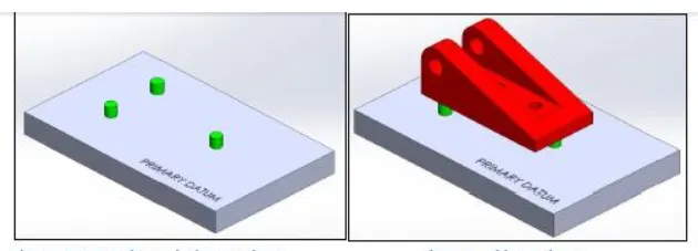
Fig 32:- Primary Datum
For the primary locating datum, the area of the triangle formed by the three locating points should be as large as possible.
2 stands For – Two locating pins in a round hole that restricts motion in the two directions in the established plane. 2 locators then position the part in a second direction (e.g., in/out). Rest the workpiece on two points of the side surface (x-z), this will fix the movement of the workpiece along the y-axis and rotation concerning the z-axis
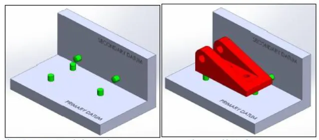
Fig 33:- Secondary Datum
For the secondary locating datum, the distance between the two locating points is as large as possible, and the line segment connecting the two locating points should be parallel to the primary locating datum if possible.
1 stands For – A Round locating Pin in a slot that restricts the rotary motion in the established plane about the round pin. 1 locator for the tertiary direction. Provide support at one point of the adjacent surface (y-z) that will fix other remaining free movements
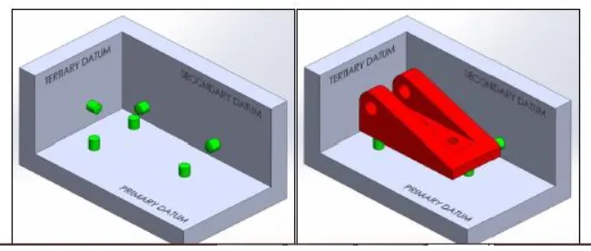
Fig 34:- Tertiary Datum
For some product designs, manufacturers replace the three locators for the secondary and tertiary directions using two round pins, one fitting a circular hole and the other a slot. The pin locates the part in two directions (e.g., in/out and fore/aft). The slot then becomes the other locator for the secondary direction (e.g., in/out).
This principle of the location of fixing points on the workpiece is also named the 3-2-1 principle of fixture design as the numbers of points selected at different faces of the workpiece are 3, 2, and 1 respectively. This approach satisfies the six degrees of freedom constraint of the part in jig/fixture design.
This approach satisfies the six degrees of freedom constraint of the part in jig/fixture design.
LOCATING SELECTION CRITERIA FOR EXAMPLE
Locating pins is the preferred choice for the primary location.
The best and most cost-effective method of part location is referred to as the 3-2-1 method.
3.) Minimum (3) locator blocks to establish the part plane.
2.) (1) Round locating pin in a round hole that defines the location in four directions (4 ways perpendicular to the plane previously established).
1.) (1) Round locating pin in a slot that defines two of the directions of the other pin (2-way)
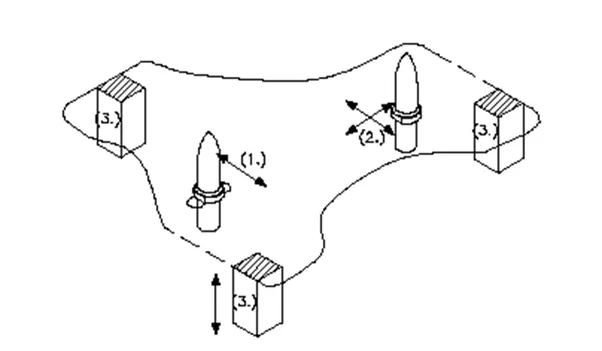
Fig 34:- 3-2-1 Principle in fixture design
Locating pins: If the angle between the hole axis and direction of loading and unloading is more than 3 deg, use a retractable pin, otherwise use a fixed pin.
- Pins must be shimmed parallel to body lines, if the location pin is at an angle then 3-direction shimming is done.
- Pins must be oriented parallel to the perpendicular of the hole or slot.
- Panel engagement with a pin flat surface should be as close as possible or 4 mm to avoid panel fouling.
- Retractable pins may be required to overcome a hole fouling condition that could cause product damage using a stationary pin ie. Multiple pins where pin center lines are not parallel, Pin center line not parallel to the direction of automatic load/unload
- Shimming is done in one direction only if the angle is < 30 deg between Mylar and the panel. it needs to be done in two directions if the angle is > 30 deg.
- L-Blocks are used in conjunction with locator blocks to provide additional planes of adjustment when required.
- Mylars touching reinforcements should be of S45C and those touching skin panels may be considered nylon to avoid scratches on the skin panels.
- Dowel position and machined face should be in the car line.
- CLAMP stoppers are used when accuracy is required in the parts in clamped condition, to grip or hold the parts during the welding process. It doesn’t touch the panel and is provided near the fulcrum. The most common stopper used is V block stopper
6. Define the Body coordinate system?
Co-ordinate system:- Coordinate systems are used to describe the position of an object in space. A coordinate system is an artificial mathematical tool that we construct in order to describe the position of a real object.
In general BCS is also called as car line or Body line
Car lines are the (Grid lines) shown on the fixture, which virtually represent the same location in the BIW. All the car lines on fixture display the coordinate at the corner for reference. With these lines one can easily relate the location in BIW.
Sometimes the single coordinate hole is given in the fixture, which also represents the car line coordinates, from that reference point fixture is made and can be inspected. Body coordinates are mentioned near the hole
Fig 35:- Body Coordinate System
-We should try that coordinatesates of locating and clamping points should not be in three decimal (e.g. X=100.124, Y=245.127, Z=450.458).
They should be in the whole nos. or max up to 1 decimal. Once these co-ordinates are maintained automatically the BIW base structure is maintained.
All vehicle product drawings are identified numerically relative to three vehicle planes Description is shown below.
1. ( X ) It is in width of BIW – 0 X - is Body Center Line
2. ( Y ) It is in the length of BIW – 0 Y is Near Front Bumper
3. ( Z ) It is in Height of BIW - 0 Z is about the Center of the Wheel
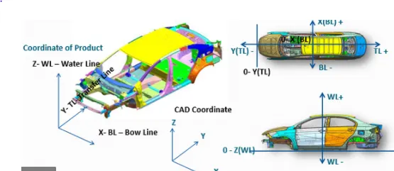
Fig 36:- Body Coordinate System
7. Elaborate Body plane system & its essentials.
Body planes are the reference plane in an automotive car. These planes are used to define the GD & T of all car parts in the automotive domain.
Body planes are three mutually perpendicular imaginary planes. These are generally considered to be present at the driver position or sometimes at the engine location or at the front end of the car depending on the customer.
The measurements from the body planes to the parts are called body line dimensions.
These body planes are called as
FOL Front “O” line.
COL Centre “O” line
BOL Body “O’ line
The measurement along FOL or X-axis is called as F/A Front aft.
The measurement along COL or Y-axis is called as C/C Cross car.
The measurement along BOL or Z-axis is called as U/DUP down.
In below figure origin is somewhere below driving sheet as it depends or changes from customer to customer. But axis system is commonly same.
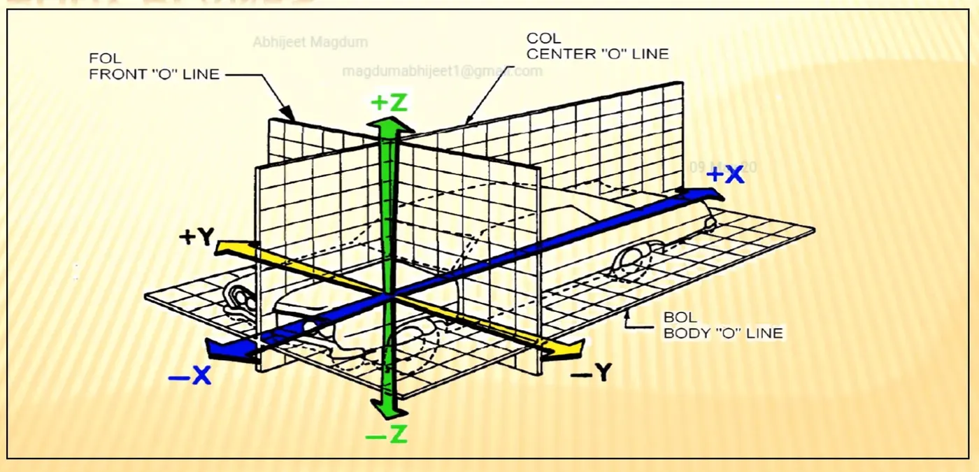
Fig 37:- Body Plane System
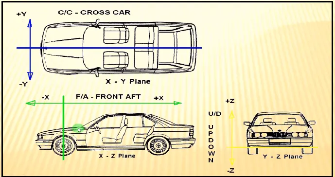
Fig 38:- Body Plane System
Bodyline dimensions are essential for the reasons stated below,
- It defines the exact position of each product in the vehicle w.r.t. a fixed origin.
- It ensures flawless design for assembly.
- While designing lines, all the designs are carried out relative to the bodyline, viz, fixture, turn table, etc.
- It assists in the easy location of different parts in a vehicle.
- It aims in creating a standardized system.
- It assists in quality checks.
These are basic essential things that body line dimension would help in BIW. It could help in designing lines like welding lines, assembly lines, or car body through fixtures & turntables, etc. This help in designing every tool. Particular assemblies or parts are designed w.r.t body lines or an axis system or car line also helps in quality while doing CMM of that system. CMM is basically done with the help of coordination. It has to relate a particular fixture with that car part, because the dimension, coordinates of hole & pin should match so it will help in quality check also. We just give coordinates that belong to that hole both coordinate should match. With this matching means quality is approved. The below figure shows some examples.
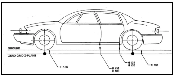
Fig 39:- X plane to define the length of car.
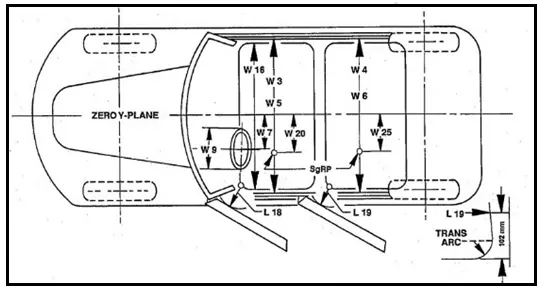
Fig 40:- Y plane to define the length of car.
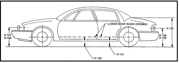
Fig 41:- Z plane to define the length of car.