Week 2:- BiW Fixture Basics Challenge
- What is the process of project execution activity?
A Project Execution Plan is a governing document that defines how a project is to be executed, monitored, and controlled.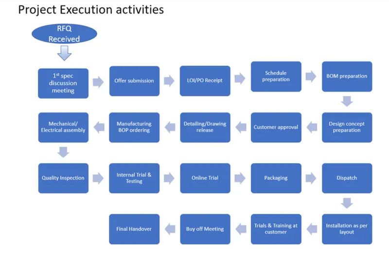
1.RFQ received
It is the first stage of the project. RFQ stands for request for quotation. The customer specifies the requirement and specification of the project in the form of data or a document. The technical offer, commercial offer and the timeline for the completion of the project are also specified by the customer.
2.1st Spec discussion meeting
After receiving the RFQ from the customer, the documents regarding the technical offer, commercial offer, and timeline are prepared. The timeline includes the time required for design, Simulation, manufacturing till the installation of the product to the customer.
3.Offer submission
The prepared document is then submitted to the customer to work on it, to check whether the requirements are met and the time period mentioned is acceptable and feasible for them.
4.LOI/PO receipt
The documents which are submitted will be studied by the customer. The customer also gets documents from other firms, compares them, and select the best offer that would suit their requirement. Once the customer chooses the best offer the purchase order is generated and the work will be started. Meanwhile, the project team does a little work on the project so that they would adhere to the timeline once the PO is given to them.
5.Schedule Preparation
After the PO is received the project officially starts and the schedule is prepared for the various stages of the project to complete the project within the specified timeline. All the activities including the time before PO receipt is added to the schedule. The time is segregated and deadlines are set for every stage to make sure the whole project gets completed within the deadline specified by the customer.
6.BOM
BOM stands for Bill of material which is prepared for the project for the parts that are required for the project like motors, cylinders, etc.
7.Design Concept Preparation.
The data is received like the 3d data from the car panel and 2d drawings from the customer along with the LOI/PO regarding the requirements. Using this data, the design concepts are prepared to fulfill the customer's needs.
8.Customer approval
After the design concept is prepared from the data provided by the customer. The designed concept is sent to the customer for approval. The customer checks whether the submitted design adheres with the technical offer or not. If it is satisfied then the customer approves the design and if not few changes will be made in the design and later will be approved.
9.Detailing and Drawing Release
Once the final approval is given by the customer after making the required changes, the design drawings are released with all the necessary details like dimensions, tolerances, etc.
10.Manufacturing / BOM Ordering
The released drawing is submitted to the manufacturing team and they start manufacturing the parts like the riser, Mylar, etc, and the parts like the motors, sensor, and cylinders are ordered.
11.Mechanical /Electrical Assembly
The ordered parts undergo prior quality control checks and also they are checked for the required specifications. Once the quality check is done the mechanical and electrical parts are assembled as per the design.
12.Quality Inspection
After the assembly again the quality inspection is done to check whether the dimensions are as per the design data, the coordinates, and accuracy. The relative dimensions between the two pins are also checked. CMM is used for inspection purposes.
13.Internal Trial and Testing
Once the assembly is quality approved, internal trial and testing are done where the assembly is put into the fixture and checked for the position of the pins and whether the clamping is proper or not. Operations like welding, Loading, and unloading are also tested during the trial.
14.Online Trial
In the Online trial, everything is done using the control panel in an automated mode and checked whether the sequence of operation is as per the specification. The customer approves the part after the online trial.
15.Packaging and Dispatch
Once the customer approves after the online trial. He asks the team to send the part for installation. The fixture is packed and proper packaging is ensured so that there is damage during the transportation of the fixture both functionally and aesthetically. After the packaging is done the fixture is dispatched to the customer.
16.Installation as per layout
A layout will be designed at a very initial level to show the position of mounting of the robot, mounting of fixtures. This layout is designed as per the functional requirements of the customer.
17.Trials and Training at the customer.
After the installation, there will be a trial at the customer's place. Production trials are to see whether the number of units processed by the fixture is meeting the requirement or not and whether the quality standards are met or not. Then training is given to the engineers, operators at the customer end regarding the controls, the operating sequence.
18.Buyoff meeting and Final Handover.
The customer will check all the requirements and whether the listed specification is available or not. Customers will sometimes give few additions and finally if the customer is satisfied with the part, the project is handed over to the customer.
- 2. What are the types of joining processes?
Mechanical fastening is the most common method of joining many materials within industry. Originally used for metal joining, it is also well established for joining plastics to themselves and to other materials. There are two main categories of industrial fasteners, permanent and nonpermanent. Screws are examples of nonpermanent fasteners, since they can be removed, replaced, and reused. These parts increase the product cost due to the increased assembly time and are more difficult to handle and align. Permanent fasteners, such as snap-fits, which are integrated into the parts through direct molding, are more robust and do not have the potential for working loose. Screws are a reliable and inexpensive method of mechanical fastening. They do not require molded-in threads or threaded inserts, reducing molding and assembly costs. Dissimilar materials can be joined, and disassembly and reassembly of the joint is possible, often up to ten disassembly/reassembly cycles. Connections have good impact resistance and are made in localized regions of the part. Full-strength joints can be obtained immediately, without the cure time associated with adhesive bonding, and no special application tools are required. Screws, nuts, bolts, and washers are nonpermanent fasteners and materials joined in this way are disassembled and reassembled a number of times until the material being joined fails. Failure is normally a result of cracking or crazing due to tensile stresses that can be induced under high pressure. Compressive stress is much more desirable due to the lower susceptibility to localized stress cracking.
Joining processes have been classified in to 2 categories namely Permanent fastenings and temporary fastenings
Permanent fastenings : in which the strength of the joined materials will be almost similar to the parent material and in this type of joints one part is going to be damaged while dismantling some of the examples of permanent joint is Welding while adhesive bonding, brazing, and soldering processes are mainly used to provide permanent joints.
Temporary fastenings: in this type of joints the strength of the jpoint will not be same to parent material but while dismantling the joint no part is going to be damaged some examples are threaded joints , riveting, gluing
In joining processes we can choose between mechanical and metallurgical joining based on the material and place of joining.
- Mechanical Fasteners
- Adhesive bonds
Adhesive Bonding is the process of joining two surfaces together, usually with the creation of a smooth bond. This may involve the use of glue, epoxy, or one of a wide range of plastic agents that bond either through the evaporation of a solvent or through curing via heat, time, or pressure.
HEMMING:
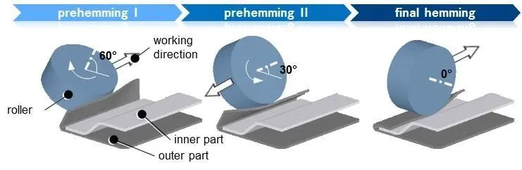
Hemming is the metalworking process in which a sheet metal edge is rolled into itself.The outer surface of the panel is rolled 2 or 3 times over the inner panel.In first roll the panel is bent slightly,and in the second roll the sheet metal is rolled even more and in the last roll it completely fits or covered the inner panel.There must be a 0.2mm gap between outer and inner panel in both upper and lower side.
Pinned (bolted) joints/connections are an extremely important, but very difficult to analyze, engineering component. They constitute a class of inverse problems whose pin/hole interface stresses are typically unknown. Failures of mechanical or structural systems often initiate at connections and their contact stresses are frequently the “Achilles’ heel”. A consequence of this multiply-connected geometry in which neither closed boundary is self-equilibrated is that stresses depend on Poisson’s ratio. Purely analytical or numerical solutions to such non-linear (contact area changes with load) problems that account for finite geometry, pin/hole friction and clearance are extremely difficult. Most pinned-joint analyses ignore friction for simplicity, but some contact friction is virtually always present. Known boundary conditions, along with some stresses from measured strains, are utilized here to evaluate the unknown coefficients of an assumed Airy stress function so as to provide the stresses throughout the entire plate. This includes the complete state of stress on the pin/hole interface. Although both pin/hole friction and clearance are accounted for here, no assumptions are made as to what is occurring on the pin/plate contact boundary.
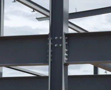
Metallurgical joining: only permanent joining processes.
- Welding
It is an economical way to join components in terms of material usage and fabrication costs. Other methods of assembly require, for example, drilling of holes and usage of rivets or bolts which will produce a heavier structure.
there are many types of welding
- Arc Welding
Arc welding is a type of welding process using an electric arc to create heat to melt and join metals. It is a fusion welding in which base metal is melted to make a joint and sometimes filler material is also used . there will be different types of welding processes in which it has been classified as Ac welding and DC welding
Out of DC welding we will be having straight polarity and reverse polarity types in which the electrode is connected to the Positive terminal then it is called as straight polarity or DCEP on the other hand if the electrode is connected to the negative terminal then it is called as DCEN.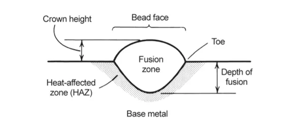
types of arc welding
- Gas tungsten arc welding
- Gas metal arc welding
- plasma arc welding
- Resistance welding
Resistance welding is the joining of metals by applying pressure and passing current for a length of time through the metal area which is to be joined.
types of resistance welding
- Spot welding
- Seam welding
- projection welding
- Resistance butt welding
Thermochemical welding
Thermit Welding
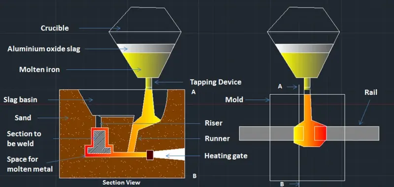
Thermit welding (TW) is a process that uses heat from an exothermic reaction to produce coalescence between metals. The name is derived from ‘thermite’ the generic name given to reactions between metal oxides and reducing agents. The thermite mixture consists of metal oxides with low heats of formation and metallic reducing agents which, when oxidized, have high heats of formation. The excess heats of formation of the reaction products provide the energy source to form the weld.
Let us consider an example; if fine aluminum particles and metal oxides are blended and ignited by an external heat source, the aluminothermic reaction will precede according to the following equation:
Metal oxide+aluminum→aluminum oxide+metal+heat
The most common thermit welds reactions are listed in the following table:
(12)
34Fe3O4+2Al→94Fe+Al2O3 (ΔH=838kJ)
(13)
3FeO+2Al→3 Fe+Al2O3 (ΔH=880kJ)
(14)
Fe2O3+2Al→2 Fe+Al2O3 (ΔH=860kJ)
(15)
3CuO+2Al→3Cu+Al2O3(ΔH=1 210kJ)
(16)
3Cu2O+2Al→6Cu+Al2O3 (ΔH=1 060kJ)
The theoretical estimated maximum temperature of the reaction listed above is 3,200°C (5,800°F). In practice however, the heat ranges between 2,200°C (4,000°F) and 2,400°C (4,350°F). The ignition temperature of the thermit granules used for welding is about 1,200°C (2,200°F), therefore it is safe from fire hazards if stored away from open heat sources.
Thermit welding is a chemical welding process in which an exothermic chemical reaction is used to supply the essential heat energy.
types of thermochemical welding
- thermit welding
- atomic hydrogen welding
- Friction welding
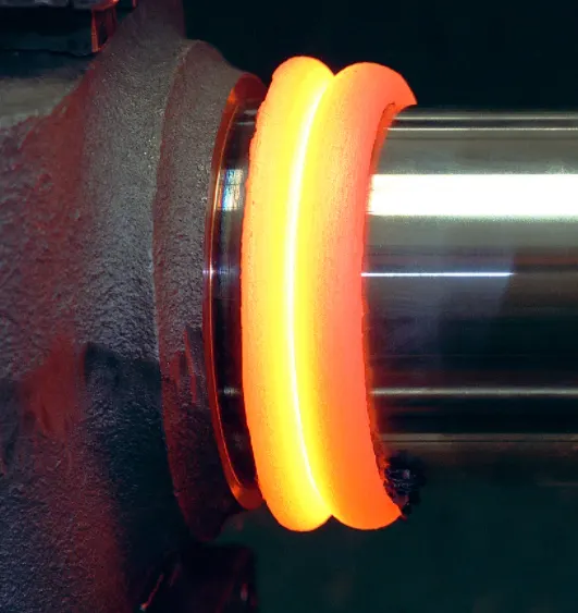
Friction welding refers to joining two metallic surfaces by the frictional heat generated at their interface due to relative motion applied between them. The parts being joined are held under high compressive load. The relative motion between the two parts can be created either by rotary motion or by linear motion of one part with respect to the other that is usually held stationary. The former process is called the rotary friction welding or spin welding (shown in Fig. 8.13) and is suitable for round surfaces (e.g., drive shafts and axles), while the latter is called linear friction welding or vibration welding and is suitable for square surfaces (e.g., bracket mounts). As the frictional heat starts to soften the materials at the interface, the applied compressive load creates a hot forging type action that forms a metallurgical bond between the two surfaces. The joint thus produced has a narrow HAZ in the plastically deformed zone adjacent to the joint, but no fusion zone. If there is any flash or extruded material on the sides, it can be removed by a later operation. One advantage of friction welding is that no preweld surface preparation is needed, since the initial rubbing action between the two surfaces removes any contaminants, oil or oxide layer that may be present on them.F
Friction welding (FRW) is a solid-state welding process that generates heat through mechanical friction between workpieces in relative motion to one another
- Brazing
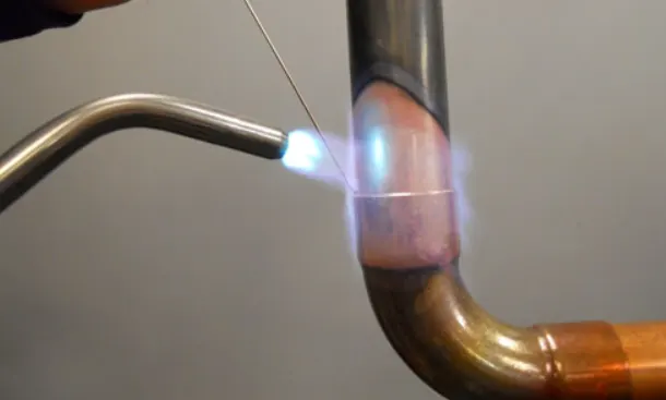
Brazing is a metal-joining process in which two or more metal items are joined together by melting and flowing a filler metal into the joint, with the filler metal having a lower melting point than the adjoining metal. Brazing differs from welding in that it does not involve melting the workpieces.
- Soldering
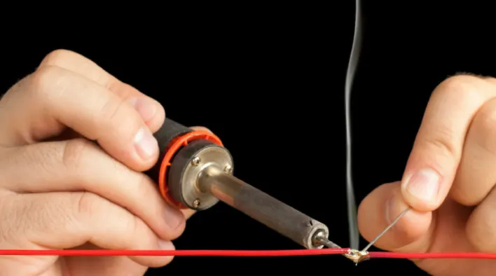
soldering is a joining process used to join different types of metals together by melting solder. Solder is a metal alloy usually made of tin and lead which is melted using a hot iron. The iron is heated to temperatures above 600 degrees Fahrenheit which then cools to create a strong electrical bon
- What is Resistance Welding & its application in the automotive sector?
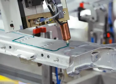
Resistance welding is the process in which two or more parts are welded by the coordinated and regulated use of heat and pressure. The heat in the resistance welding process is generated by the resistance offered by the workpieces to the flow of low voltage high-density electric current. The resistance welding processes include spot welding, seam welding, roll spot welding, projection welding, upset welding, flash welding,,, and percussion welding.
Resistance welding is one of the oldest of the electric welding processes in use by industry today. The weld is made by a combination of heat, pressure and time. As the name resistance welding implies, it is the resistance of the material to welded, to current flow that causes a localized heating in the part.
The pressure exerted by the tongs and electrode tips, through which the current flows, holds the parts to be welded in intimate contact before, during and after the welding current time cycle. The required amount of time current flows in the joint is determined by material thickness and type, amount of time current flowing and the cross-sectional are of the welding tip contact surfaces.
Fundamentals of Resistance Welding
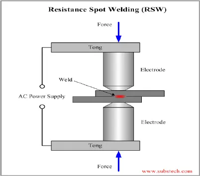
Resistance spot welding is accomplished when current is caused to flow through the electrode tips and the separate pieces of metal to be joined. The resistance of the base metal to electric current flow causes localized heating in the joint and the weld is made.
The resistance spot weld nugget is formed internally with relation to the surface of the base metal. The below illustration shows a resistance spot weld nugget compared to a gas tungsten – arc spot weld.
The gas tungsten – arc spot is made from one side only. The resistance spot weld is normally made with the electrodes on each side of the workpiece. Resistance spot welds may be made with the workpiece in any position.
The resistence spot weld nugget is formed when the interface of the weld joint is heated due to the resistance of the joint surfaces to electric current flow. In all cases, of course, the current flow MUST flow or the weld can not be made. The pressure of the electrode tips on the work piece holds the part in close and intimate contact during the making of the weld. Remember however, that resistance spot welding machines are NOT designed as force clamps to pull the workpieces together for welding.
1 – Heat Generation
A modification of Ohm’s Law may be made when watts and heat are considered synonymous. When current is passed through a conductor the electrical resistance of the conductor to current flow will cause heat to be generated. The basic formula for heat generation may be stated:
H = I R where:
H= HEAT, I2 = WELDING CURRENT SQUARED, and R= RESISTANCE
The secondary portion of a resistance spot welding circuit, including parts to be welded, is actually a series of resistances. The total additive value of this electrical resistance affects the current output of the resistance spot welding machine and the heat generation of the circuit.
The key fact is, although current value is in the same in all parts of the electrical circuit, the resistance values may vary considerably at different points in the circuit.
The resistance spot welding machines manufactured by Miller Electric Mfg. Co. are constructed so minimum resistance will be apparent in the transformer, flexible cables, tongs and electrode tips. Miller resistance spot welding machines are designed to bring the welding current to the weldment in the most efficient manner. It is at the weldment that the greatest relative resistance is required. The term “relative” means with relation to the rest of the actual welding circuit.
Resistance welding is the joining of metals by applying pressure and passing current for a length of time through the metal area which is to be joined.
types of resistance welding
- Spot welding
- Seam welding
- projection welding
- Resistance butt welding
- Resistance spot welding
In this process, the fusion of electrodes is done by electrodes having opposing charges at one location. The sheet thickness has to be less than 3 mm for a good spot weld.
- Seam welding
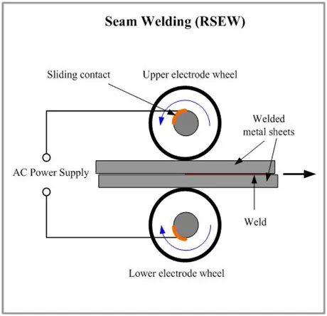
In principle, seam welding is similar to spot welding except that it uses disc-shaped electrodes. Unlike spot welding,,, the disc-shaped electrodes are not separated after each weld but maintain a continuous pressure over the workpieces.
- Flash welding
Flash welding is a type of resistance welding that does not use any filler metals. The pieces of metal to be welded are set apart at a predetermined distance based on material thickness, material composition, and desired properties of the finished weld.
Its applications in the automotive sector are
Resistance Spot Welding (often just called spot welding) is a cost-effective joining technology that continues to be very popular in the automotive industry where high reproducibility and automation are essential criteria. resistance spot welding has proven itself as the dominant technology when joining thin metal sheets.
In particular, the automotive industry continues to use resistance spot welding as its main joining process, despite strong competition from the processes of beam welding, adhesive bonding,,, and mechanical joining. The main reason for this are that resistance spot welding offers high productivity at a low cost and is therefore, likely to maintain its position into the future.
- Resistance welding is used in mass production for welding sheet metal, wire,and tubes.
- It is used in welding bars, boxes, cans, rods, pipes, and frames metals of medium and high resistance materials such as steel, stainless steel, money metal, and silicon bronze which are easy to weld.
- It is used for making fuel tanks for cars, tractors, etc.
4. What is fusion welding & types of fusion welding with its application in the automotive sector?
Welding is a fabrication process whereby two or more parts are fused together by means of heat, pressure or both forming a join as the parts cool. Welding is usually used on metals and thermoplastics but can also be used on wood. The completed welded joint may be referred to as a weldment.
Some materials require the use of specific processes and techniques. A number are considered 'unweldable,' a term not usually found in dictionaries but useful and descriptive in engineering.
The parts that are joined are known as a parent material. The material added to help form the join is called filler or consumable. The form of these materials may see them referred to as parent plate or pipe, filler wire, consumable electrode (for arc welding), etc.
Consumables are usually chosen to be similar in composition to the parent material, thus forming a homogenous weld, but there are occasions, such as when welding brittle cast irons, when a filler with a very different composition and, therefore, properties is used. These welds are called heterogeneous.
It is an economical way to join components in terms of material usage and fabrication costs. Other methods of assembly require, for example, drilling of holes and usage of rivets or bolts which will produce a heavier structure.
there are many types of welding
- Arc Welding
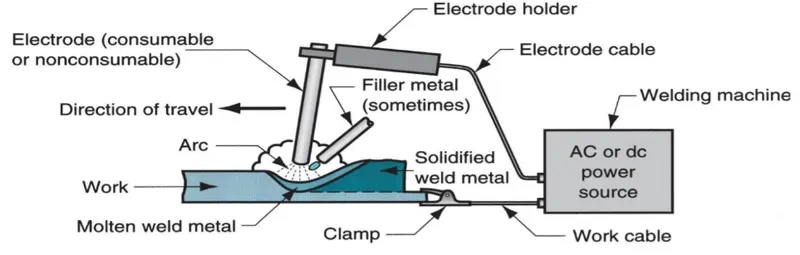
Arc welding is a type of welding process using an electric arc to create heat to melt and join metals. It is a fusion welding in which base metal is melted to make a joint and sometimes filler material is also used . there will be different types of welding processes in which it has been classified as Ac welding and DC welding
Out of DC welding we will be having straight polarity and reverse polarity types in which the electrode is connected to the Positive terminal then it is called as straight polarity or DCEP on the other hand if the electrode is connected to the negative terminal then it is called as DCEN.
- Gas welding
Gas-welding process involves the utilization of a centered and outrageous high-temperature burst which is created by the consumption of gas or gases blend (Ogundimu, 2017). This engaged blast is then used to condense the workpieces to be joined; combined with an outer filler material for legitimate welding. Oxyacetylene gas welding is the most widely recognized sort of gas-welding process. In oxyacetylene gas welding, a blend of oxygen and acetylene combusts and produces fire at a temperature of around 3500°C. At the point when the engaged fire gets in contact with the workpieces, it softens the surface framing a liquid pool and surrendering welding to occur (Shiri, Nazarzadeh, Sharifitabar, & Afarani, 2012). This welding procedure can likewise be utilized for brazing, bronze welding, molding metal, and cutting. Other fusion welding classification includes
Gas welding involves the melting of base metal and filler metal is used, through the flame produced at the tip of a welding torch.
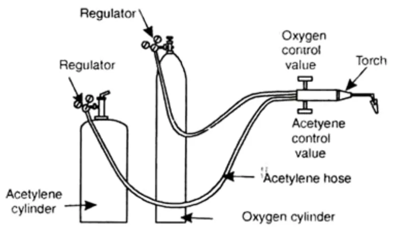
types of gas welding
- oxy-acetylene gas weld
- oxyhydrogen gas weld
- air- acetylene gas weld
- pressure gas weld
Friction welding
Friction welding refers to joining two metallic surfaces by the frictional heat generated at their interface due to relative motion applied between them. The parts being joined are held under high compressive load. The relative motion between the two parts can be created either by rotary motion or by linear motion of one part with respect to the other that is usually held stationary. The former process is called the rotary friction welding or spin welding (shown in Fig. 8.13) and is suitable for round surfaces (e.g., drive shafts and axles), while the latter is called linear friction welding or vibration welding and is suitable for square surfaces (e.g., bracket mounts). As the frictional heat starts to soften the materials at the interface, the applied compressive load creates a hot forging type action that forms a metallurgical bond between the two surfaces. The joint thus produced has a narrow HAZ in the plastically deformed zone adjacent to the joint, but no fusion zone. If there is any flash or extruded material on the sides, it can be removed by a later operation. One advantage of friction welding is that no preweld surface preparation is needed, since the initial rubbing action between the two surfaces removes any contaminants, oil or oxide layer that may be present on them.
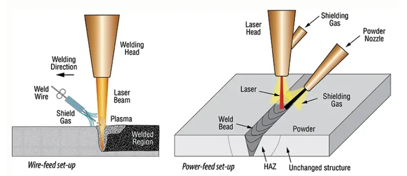
Laser Beam welding
Laser welding utilizes a laser beam as a concentrated heat source to join multiple pieces together. Delivering a focused heat source, laser welding creates a strong seam at a high speed.
The processes and applications of laser welding are most prominent in the automotive industry, where lasers boost productivity at a low cost when welding automotive parts – such as roof, door, or filter assemblies – together.
5. What is the 3-2-1 principle?
3-2-1 Principle
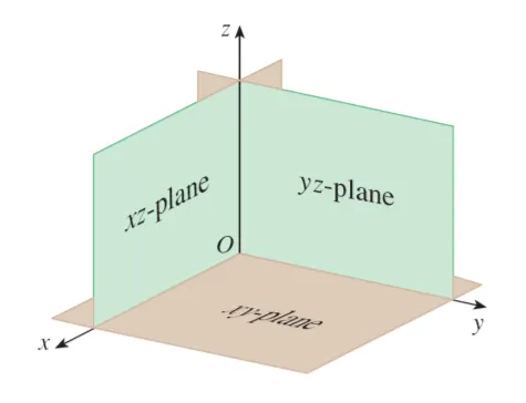
- The 3-2-1 method is a work-holding principle where three pins are located on the 1st principle plane, i.e., either XY, YZ, ZX. And two pins are located on the 2nd plane perpendicular to the 1st plane, and at last, one pin on the plane is mutually perpendicular to the 1st and 2nd planes.
- It represents the minimum requirement for the locating elements.
- The locators along with the clams which hold the part in place, provide equilibrium for all the forces.
- Stability is satisfactory if all three rest buttons are widely spaced and the resulting cutting force lies within the triangular area between the buttons.
- If the resultant cutting force lies outside the triangular area then it generates a moment which in turn lifts or overturns the component.
Degrees of Freedom
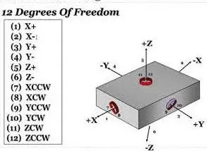
There are 12 degrees of freedom of a workpiece, movement about the negative and positive axis and clockwise and anti-clockwise rotation about the three axis.
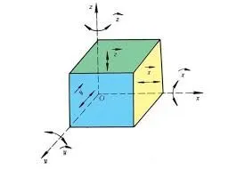
There are 6 translational degrees of freedom +X, -X, +Y, -Y, +Z, -Z,
6 rotational degrees of freedom which are
- Clockwise around X axis (CROT-X)
- Anticlockwise around X axis (ACROT-X)
- Clockwise around Y axis (CROT-Y)
- Anticlockwise around Y axis (ACROT-Y)
- Clockwise around the Z axis (CROT-Z)
- Anticlockwise around the Z axis (ACROT-Z)
We must fix all the 12 degrees of freedom except the three translational degrees of freedom (-X, -Y and -Z) in order to locate the work piece in the fixture. So, the 9 degrees of freedom of the workpiece needs to be fixed.
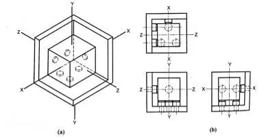
The jig and fixture are tools used for holding the work piece in a correct location for mass production. Various types of fixtures (like drilling fixtures, milling fixtures, and welding fixtures) are used in industry. The 3-2-1 method is the fundamental principle for all types of fixture design.
Translational & rotational position along the X-axis
Translational & rotational position along the Y-axis
Translational & rotational position along the Z-axis
These six coordinates are known as the six degrees of freedom of a three-dimensional object. The translational and rotational positions can vary in either direction concerning each of the three axes.
To completely prevent movement, all six degrees of freedom must be restricted.
So, to arrest each DOF Fixtures are used to contain the part for working.
- Define Body coordinate system?
In geometry, a coordinate system is a system that uses one or more numbers, or coordinates, to uniquely determine the position of the points or other geometric elements on a manifold such as Euclidean space. The order of the coordinates is significant, and they are sometimes identified by their position in an ordered tuple and sometimes by a letter, as in "the x-coordinate".
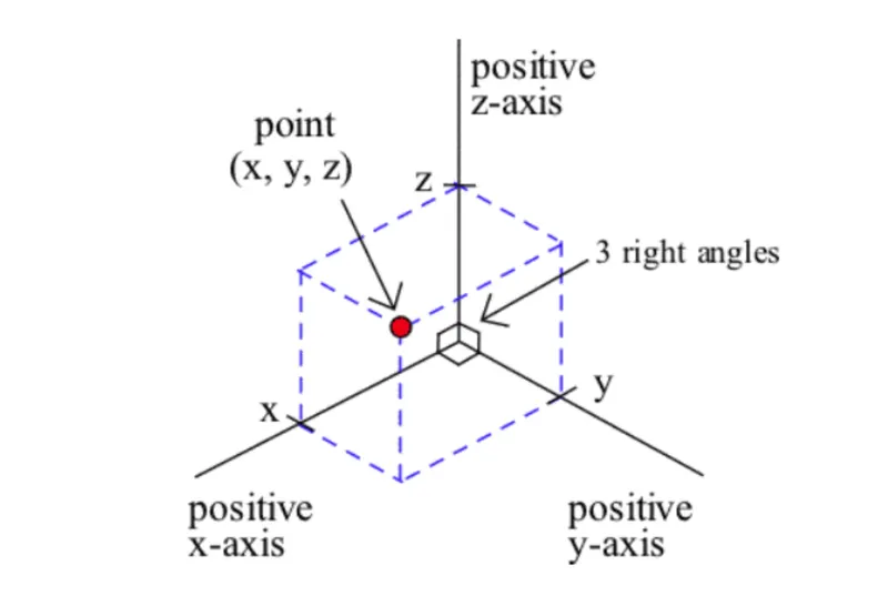
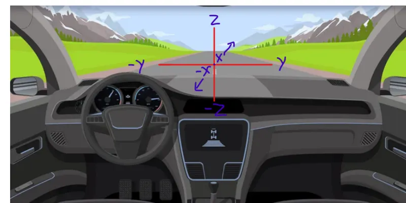
In-Vehicle body coordinate system. the (XYZ) coordinates are defined as,
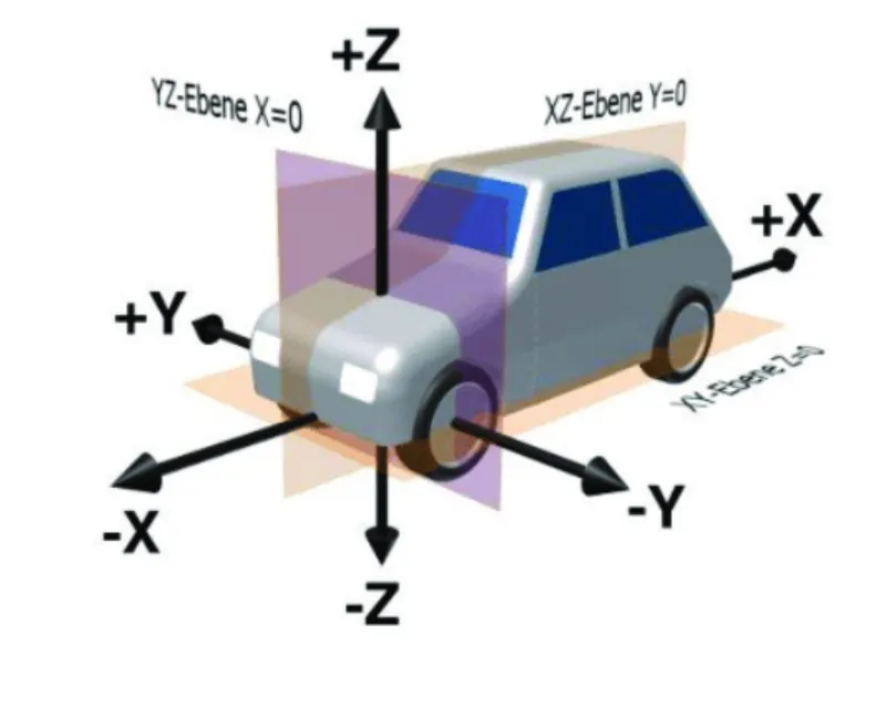
A coordinate system is used for the positioning of the points, lines, or even parts as in the design perspective
if we take an example from the driver's point of view, we can understand the coordinate system more easily
- A driver's front and back view from the vehicle is called ( X and - Xaxis). In automotive industries, these x coordinates are mentioned as " car forward and Car Rearward".
- A driver's left and right side view from the vehicle is called ( Y and - Y-axis). in automotive industries, these Y coordinates are mentioned as" car outboard and car inboard".
- A driver's top and bottom side view from the vehicle is called ( Z and - Zaxis).
- Elaborate Body plane system & its essentials.
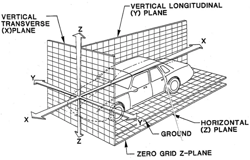
A plane system is used to create the points or lines on a particular view or surface.
The essentials of plane system is,
- By using plane system we can maintain standards within country.
- by using plane system for creation of single parts, the assembling is easier.
- by coordinate plane system we can identify the points or parts location quickly.