Advanced Sheet Metal Design Using NX Cad Challenge_2_Box Assembly
1. TITLE : Modeling of BOX ASSEMBLY using NX CAD Sheet metal
2. Objective : Draw Casing in NX CAD using Sheet Metal workbench and list the procedure like tools used to create BOX ASSEMBLY
3. Introduction : A Sheet Metal is a engineering raw material which is used to make car bodies, aircraft bodies, food beverages tins, etc. if the thickness of the sheet is less than 6 mm then it is called as sheet metal on the other hand if the thickness of the sheet is greater than 6 mm then it is called as metal plank. These sheets have to undergo various operations to get in to a requires shape , these shapes have to pre designed in drawing sheet by designer which will be a blueprint for the production department,
The blueprint can be made by manually or conventional method or we can give the blueprint in a soft copy by using CAD tools.
In this project we are using NX CAD version 12, Sheet Metal Design to draft a casing. NX CAD is software with various work benches in it , this software is developed by SIEMENS company
4. Approach :
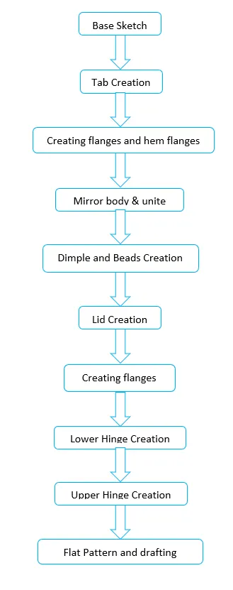
5. Description :
Tools used in this project
1.Sketch
2.Tab
3.Flange
4.Closed Corner
5.Flange for making hem
- Hem Flange
- Mirror Body
- Unite
9.Dimple
- Beads
- Hem Flange
- Tab For Lid Creation
- Flange for Lid
- Un Bend
- Cutout
- Re Bend
- Drafting
Explanation of Tools
1.Sketch: it is a tab in which we can create 2D sketches and give the required dimensions by incorporating different geometrical shapes like rectangle , line, curve, circle etc, this 2D sketch is used for the 3D developments by using Tab option
2.Tab: creates a base feature by extruding a sketch along a vector by a thickness value or adds a material to a plane face
3.Flange : Adds a flange to an angle to a planar face and adds a bend between the two
4. Closed Corner : Used to close a corners where two adjacent flanges meet by extending the bends and flanges
5. Hem Flange : It is used to modify the model by folding the edge of a flange. The main purpose of this feature is to increase the stiffness and safe handling.
6. Mirror Body : This feature is used to make a copy of the half sketch or solid body along any axis
7. Unite : This feature is used to unite the mirrored bodies to make it as a single body
8.Dimple :this command lifts an area of the model inside a sketch that simulates stamping a tool.
9.Bead : Lifts a material along a counter of sketch that simulates stamping a tool
10.Undbend : It makes the part unbend that all the features done are made flat. This is useful while sketching on the corners and bends
11.Cut Out : it is used to create a pocket in desired shape, one can remove material by sketching the shape on the solid body and using this Cut Out tab
12.ReBend : This command puts back all the bends already created also along with a new feature includes while in unbent state
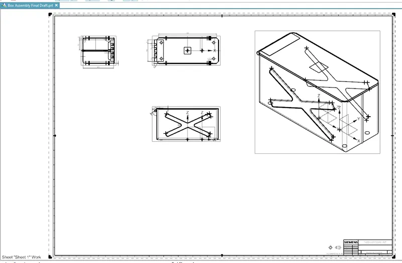
13.Drafting : it is the blueprint which is submitted to the production department , this drawing have all the necessary dimensions along with tolerances if any and it will be in 2D drafting
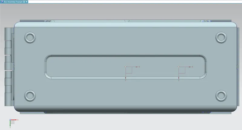
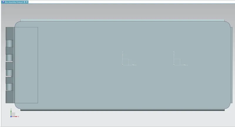
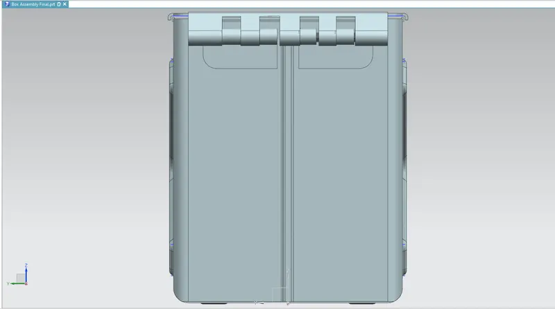
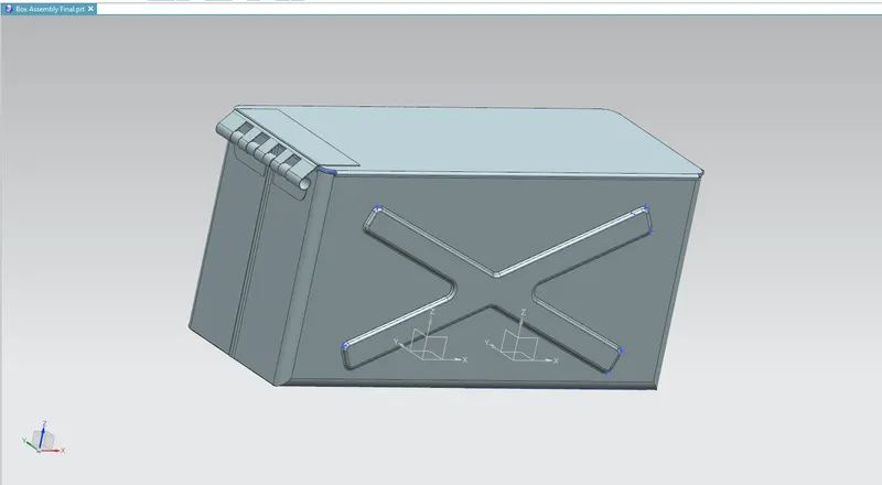
6. MODEL IMAGES
Bottom View
Top View
Side View
Isometric View
Drafting
7. Conclusion : The Box Assembly have been drafted by using NX CAD software version 12