Advanced Sheet Metal Design Using NX Cad Challenge_6_Bracket
1. TITLE : Modeling of BRACKET using NX CAD Sheet metal
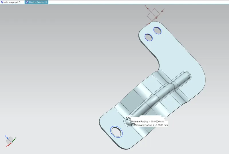
2. Objective : To Draw 3D BRACKET in NX CAD using Sheet Metal workbench by using 2D drawing and list the procedure like tools used to create BRACKET
3. Introduction : Brackets found their application for mounting of any products starting from antennas to TV, projectors or street lights and many more.These are manufactured by conducting stamping or die casting operation. it is sheet metal component have to be designed according to the requirement in a presize manner this can be achived by drafting in NX CAD Software by using various commands loke Sketch, TAB, Hole, Bead etc.
Brackets typically consist of two or more planes connected along one edge, and often to simplest way to fabricate this kind of object is to bend a flat object (i.e. a piece of sheet metal) in two or more places: the simplest example would be adding a 90° bend to a flat rectangle with a straight profile .
These sheets have to undergo various operations to get in to a required shape , these shapes have to pre designed in drawing sheet by designer which will be a blueprint for the production department,
The blueprint can be made by manually or conventional method or we can give the blueprint in a soft copy by using CAD tools.
In this project we are using NX CAD version 12, Sheet Metal Design to draft a casing. NX CAD is software with various work benches in it , this software is developed by SIEMENS company
4. Approach :
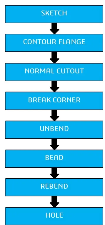
5. Description :
Tools used in this project
1.Sketch
2.Tab
3.Cut Out
4.Contour Flange
5.Break Corner
6.Undbend
7.Bead
8.ReBend
9.Hole
10.Drafting
Explanation of Tools
1.Sketch: it is a tab in which we can create 2D sketches and give the required dimensions by incorporating different geometrical shapes like rectangle , line, curve, circle etc, this 2D sketch is used for the 3D developments by using Tab option
2.Tab: creates a base feature by extruding a sketch along a vector by a thickness value or adds a material to a plane face
3.Cut Out : it is used to create a pocket in desired shape, one can remove material by sketching the shape on the solid body and using this Cut Out tab
4. Contour Flange : This feature is used to create a base feature by extruding sketch along a vector or it adds material along the edge or chain of edges of the sketch by using this feature many complex shapes can be easily created by just creating the sketch of the edge and extruding it.
5. Break Corner : this commands allows to rounding off the sharp corners
6. Undbend : It makes the part unbend that all the features done are made flat. This is useful while sketching on the corners and bends
7.Bead : Lifts a material along a counter of sketch that simulates stamping a tool
8.ReBend : This command puts back all the bends already created also along with a new feature includes while in unbent state
9.Hole : his command allows user to create a hole in the part by sketching a point on the sheet metal
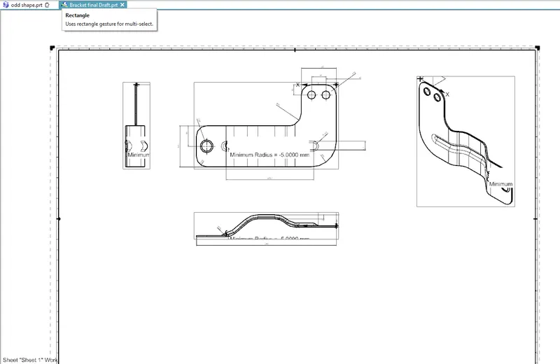
10.Drafting : it is the blueprint which is submitted to the production department , this drawing have all the necessary dimensions along with tolerances if any and it will be in 2D drafting
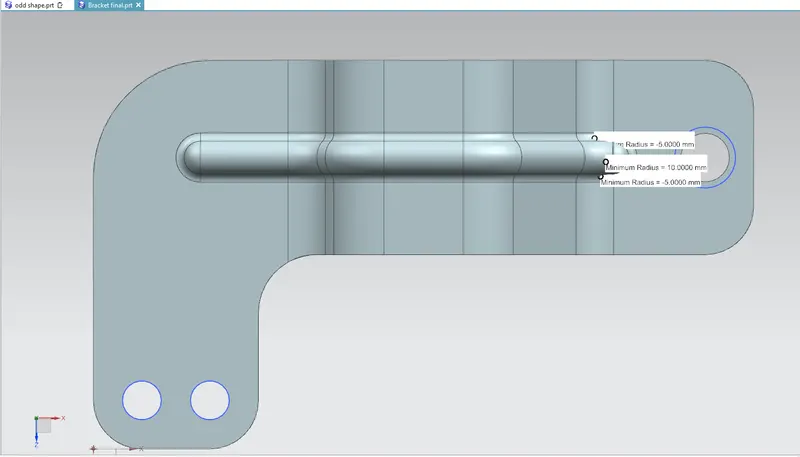
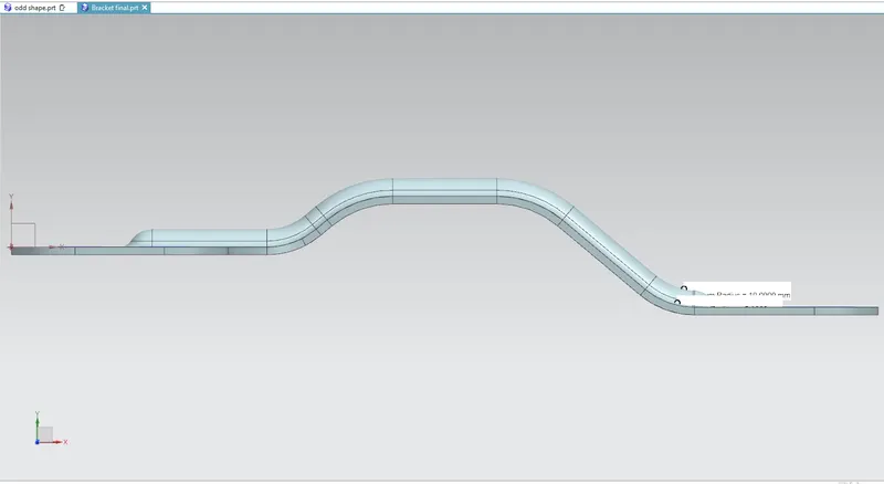
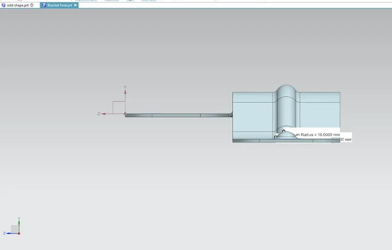
6. MODEL IMAGES
Top View
Front View
Side View
Isometric View
Drafting
7. Conclusion : The Bracket have been drafted by using NX CAD software version 12