Week 2:- BiW Fixture Basics Challenge
Week 2:- BiW Fixture Basics Challenge
Hello sir,
Question No:-1. What is the process of project execution activity?
Answer:-
PROJECT ACTIVITIES
Project Activity is basically a milestone, a section, or a task that has many sub-tasks under it. In simple words, any activity that requires a number of tasks to be completed in order to complete that activity is known as a project activity.
Steps to be followed by project activities......
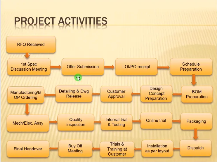
RFQ Received:
This is the first step in the project RFQ stands for Request for Quotation. This customer gives the requirements or specifications in detail for the given projects in the form of data or documents. The customer gives Technical offers, Commercial offers, and a timeline for the project and asks for a quotation of the overall project.
1st Spec Discussion Meeting:
After the Technical requirements, Specifications, Technical offers, Commercial offers, and Timeline received from the customer. The overall data is going to be analyzed with certain terms like 3D Design concept, Analysis of Design, simulation validation of Design, Quality check, 2D drawing Release, Manufacturing, Assembly installation, and commissioning. Then the cost of the overall process and Time is considered and Final Quotation is submitted to the Customer.
Offer Submission:
After the finalization of the Quotation in the meeting, the offers will be submitted from the customer's end. Based on the Technical cost, Quality, Standard, and Brand name of the Industry, the customer will be finalizing the offer.
LOI/PO receipt:
Customers will not be restricted to taking quotations from a single company, they will take quotations from different companies and they will compare quotations and choose one company which suits them best and they put an order to the company which is known as PO
(Purchase Order). After getting a PO from the customer, the company should start working on the project.
Schedule preparation:
Once the PO is received from the customer, the project will start by preparing a schedule of the project to be complete by the deadline. It is prepared by considering certain terms like Design data study, 3D design, Simulation validation, Manufacturing, Assembly, Release of BOM, Finishing, Installation, Trial Run, and Quality check. Then the schedule is prepared by allotting time to specific processes for certain employees and allotting shifts accordingly by considering accidental situations (if the specific process is not completed in the allotted time).
BOM preparation:
A bill of materials (BOM) is a comprehensive inventory of the raw materials, assemblies, subassemblies, parts, and components, as well as the quantities of each, needed to manufacture a product. In a nutshell, it is the complete list of all the items that are required to build a product.
Design Concept Preparation:
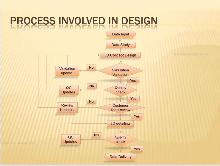
Based on the data given by the customer, we have to study the data, of consumer requirements. By analyzing all the requirements Rough sketches of the Fixture with all its sub-assembly are sketched and the flow of the overall design process is assumed. It is designed by considering the load acting on the panel, stages of welding processed, avoiding interference between welding guns, type of welding, spot plan, welding position, and time of each process. In design concept preparation, the design of the layout is been prepared at a very initial level which gives the information about continuing robots and fixtures.
Customer Approval:
After finalizing the design of the Fixture, which is ready for Fabrication with all the requirements given by the customer. A call will be given to the customer to review the design according to the need and corrections will be given by the customer. Corrections are rectified by the team and the customer will give the Final Approval for the project for continuing further process.
Detailing & Drawing Release:
Once the customer approves the design, a detailed 2D drawing design will be released by the designing team to the manufacturing team which contains all the parts with specified dimensions necessary for manufacturing.
Manufacturing/BOP Ordering:
The mechanical and electrical parts like sensors, cylinders, etc. required for manufacturing the product are ordered as per the design specifications.
Mech/Elec. Assy:
Once all the parts are received then a Quality control check will be done as per the requirements. After checking Mechanical or Electrical assemblies are prepared as per the design.
Quality Inspection:
After all the parts get assembled once again the quality check is done by checking all the dimensions and position using the CMM machine.
Internal Trial & Testing:
After the QC check is done internal trials are taken to check whether it operates as per the requirement. The simulation of the design is done before project execution for this purpose. This Fixture is checked with clamping, welding, and positioning of the workpiece.
Online Trail:
After the Internal trial and Testing Online Trial will be done. In this, the Fixture does work automatically through all electrical connections. The online Trial will be done under customer surveillance for the approval of the customer as per this design requirements. The process sequence of operations is checked as per the design way.
Packaging:
To reduce damage to the fixture while transportation packaging of different assemblies is done. After QC passes packaging is done as per standards. Different companies follow different packaging standards.
Dispatch:
After proper packaging of the product then the product is ready to dispatch.
Installation as per layout: The design of the layout is done at very initial levels. According to the functionality, operation, process, and sequence layout is done. As per the layout installation of different assemblies is done.
Trials & Training at Customer:
Production trials will be done with the customer. The company team should produce the required no. of parts using our products as per the technical offers given by the company at the beginning. Once the outcome is achieved training is given to the employees, and engineers who are involved in that process. The sequence of operations will be explained in detail.
Buy Off Meeting:
After production trials at the customer end. In this meeting, the customer will check all the requirements as per the finalized quotation and gives a review of the fixture, if he wants any additional work regarding the product, that will be done.
Final Handover:
The documents related to the fixture will be handover to the customer. Clamp validation documents and design documents will be handover to the customer.
Question No: 2. What are the types of joining processes?
Answer:
METALLURGICAL JOINING
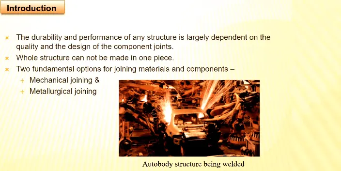
Joining Comprises a large number of processes used to assemble individual parts into a larger, more complex component or assembly. The individual parts of a component meet at the joints. Joints transmit or distribute forces generated during service from one part to the other parts of a component that meet at the joints. Joints transmit or distribute forces generated during service from one part to the other parts of the assembly. A joint can be either temporary or permanent. The five joint types that are predominately used in the joining of parts are the butt, tee, corner, lap, and edge joints.
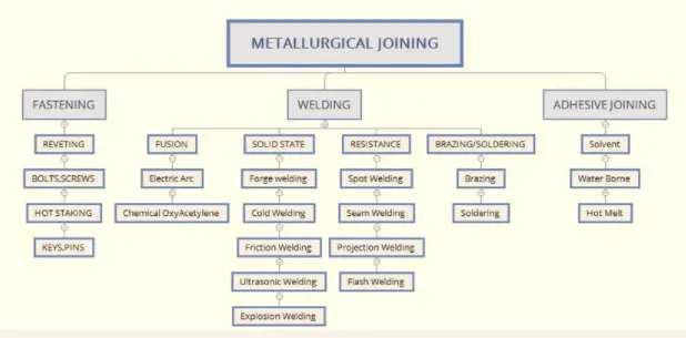
Classification of metallurgical joining
 `
`
FASTENING: A Fastener is a hardware device that mechanically joins or affixes two or more objects together. In general, fasteners are used to create non–permanent joints; that is, joints that can be removed or dismantled without damaging the joining components. Welding is an example of creating permanent joints. Steel fasteners are usually made of stainless steel, carbon steel, or alloy steel.
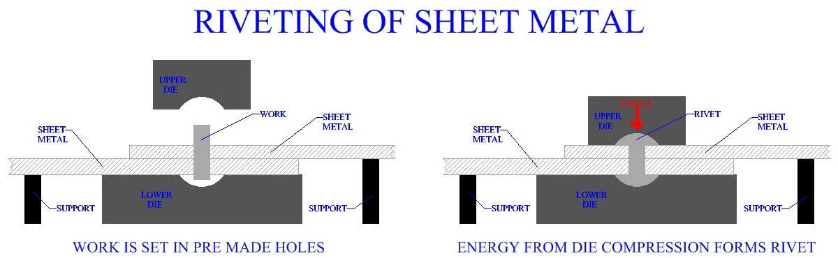
REVERTING:
- When installed the rivet is either drilled, placed, or punched into a hole, afterwards the tail is then deformed, holding the rivet in place.
- The rivet is deformed by pounding or smashing of the tail, which makes the material flatter and usually causes the tail to be expanded by about one and a half times the size of the stem’s original diameter.
- When finished the tail has the appearance of a dumbbell shape completing the riveted joint.
- Riveting can create either lap or butt joints with a variety of different rivet configurations, including single, double and zig-zag formations.
BOLTS, SCREWS: Many threaded fasteners can be described as either screws or bolts, depending on how they are used. Bolts are often used to make a bolted joint. This is a combination of the nut applying an axial clamping force and also the shank of the bolt acting as a dowel, pinning the joint against sideways shear forces.
HOT STAKING: Staking is the process of connecting two components by creating an interference fit between the two pieces. One workpiece has a hole in it while the other has a boss that fits within the hole. The boss is very slightly undersized so that it forms a slip fit. A staking punch is then used to expand the boss radially and to compress the boss axially so as to form an interference fit between the workpieces. This forms a permanent joint.
KEYS, PINS: Keys and pins are used to prevent relative rotary motion between machine parts intended to act together as one piece.
WELDING:
Welding is a fabrication or sculptural process that joins materials, usually metals or thermoplastics, by using high heat to melt the parts together and allowing them to cool, causing fusion. These are categorized into four types as follows,
FUSION WELDING: Fusion welding is a process that uses heat to join or fuse two or more materials by heating them to a melting point. The process may or may not require the use of filter material. These are categorized into four types as one piece.
ELECTRIC ARC WELDING: Arc welding is a type of welding process using an electric arc to create heat to melt and join metals. A power supply creates an electric arc between a consumable or non – consumable electrode and the base material using either direct (DC) or alternating (AC) currents.
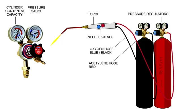
CHEMICAL OXY – ACETYLENE WELDING: Oxyacetylene welding, commonly referred to as gas welding, is a process that relies on the combustion of oxygen and acetylene.
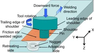
SOLID STATE WELDING: Solid State Welding is a welding process, in which two workpieces are joined under a pressure providing intimate contact between them and at a temperature essentially below the melting point of the parent material. The bonding of the materials is a result of the diffusion of their interface atoms. These are different types as follows,
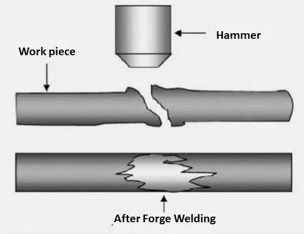
FORGE WELDING: Forge welding (FOW) is a solid-state welding process that joins two pieces of metal by heating them to a high temperature and then hammering them together.
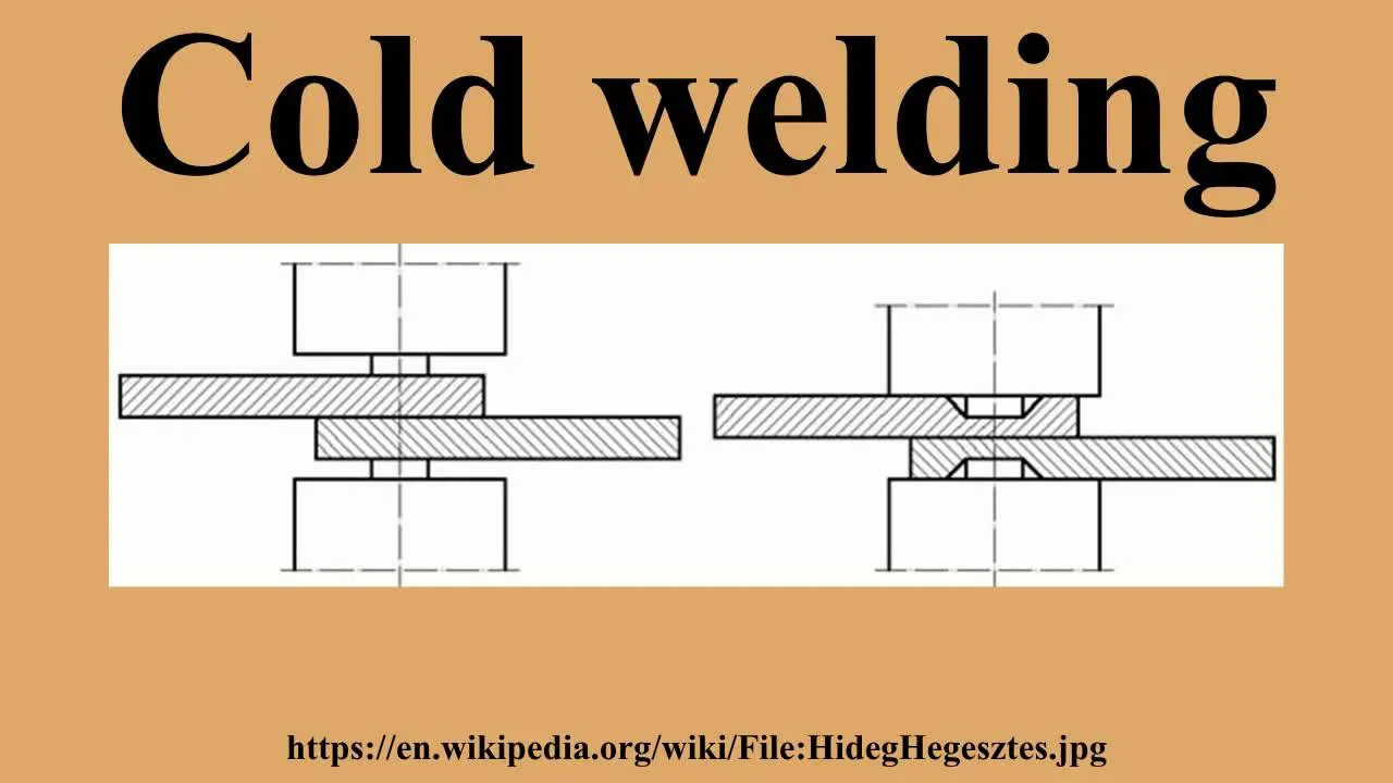
COLD WELDING: Cold welding or contact welding is a solid-state welding process in which joining takes place without fusion/ heating at the interface of the two parts to be welded. Unlike in the fusion–welding processes, no liquid or molten phase is present in the joint.
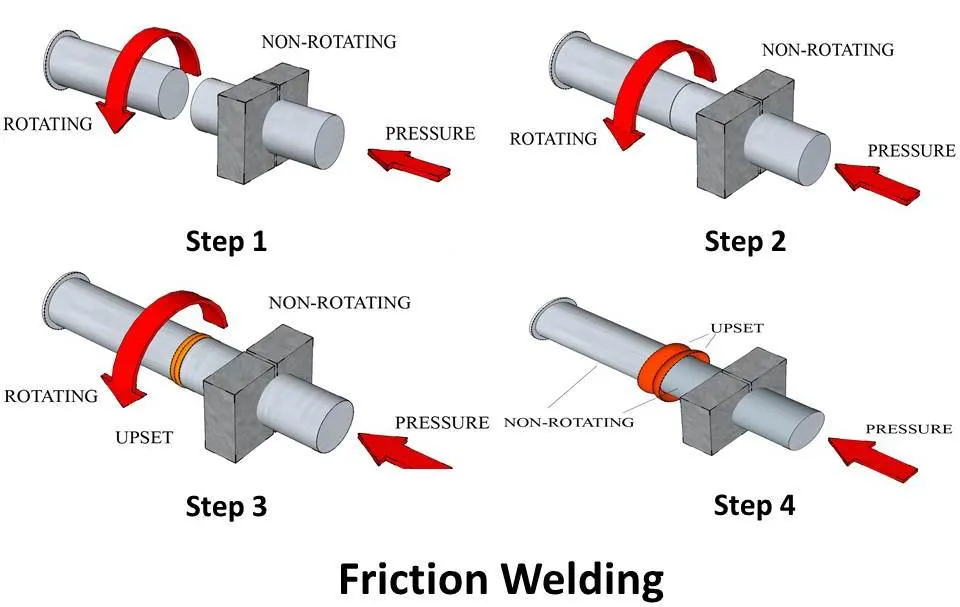
FRICTION WELDING: Friction welding (FRW) is a solid-state welding process that generates heat through mechanical friction between workpieces in relative motion to one another, with the addition of lateral force called “upset” to plastically displace and fuse the materials.
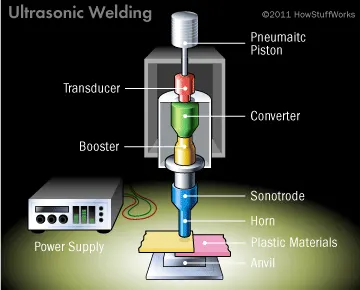
ULTRASONIC WELDING: Ultrasonic welding is an industrial technique whereby high–frequency ultrasonic acoustic vibrations are locally applied to workpieces being held together under pressure to create a solid-state weld.
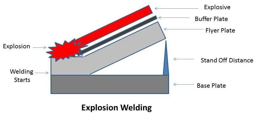
EXPLOSION WELDING: Explosion welding (EXW) is a solid-state (solid-phase) process where welding is accomplished by accelerating one of the components at an extremely high velocity through the use of chemical explosives.
RESISTANCE WELDING: Resistance welding is the joining of metals by applying pressure and passing current for a length of time through the metal area which is to be joined. The key advantage of resistance welding is that no other materials are needed to create the bond, which makes this process extremely cost-effective.
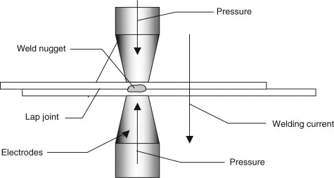
There are several types as follows
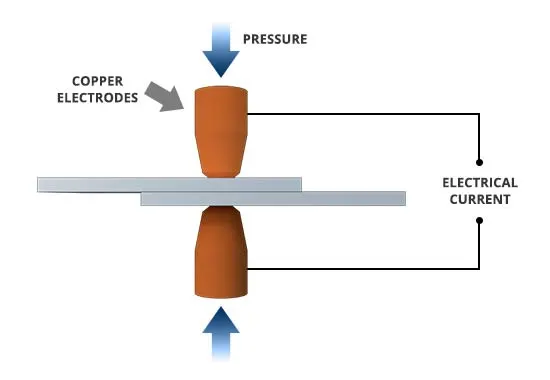
SPOT WELDING: Spot welding (or resistance spot welding) is a type of electric resistance welding used to weld various sheet metal products, through a process in which contacting metal surface points are joined by the heat obtained from resistance to electric current.
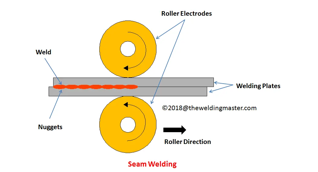
SEAM WELDING: Seam welding is the most expanded technique for on-live welding as a continuous process to ensure coil-to-coil assembly at the entry of continuous annealing lines and galvanizing lines. This is a resistance welding technique that requires an overlap of the two extremities of the coils so one can be joined to another. Seams are copper-based, round electrodes that ensure current conduction and the joule heating effect.
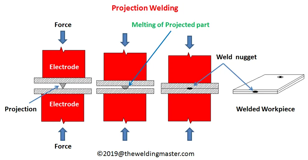
PROJECTION WELDING: Projection welding is a resistance weld where the design or shape of the part is used to make discreet individual point contacts to concentrate the current during the welding process. In most applications, multiple small projections are formed on one surface of the parts to be welded.
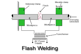
FLASH WELDING: Flash welding is a type of resistance welding that does not use any filler metals. The pieces of metal to be welded are set apart at a predetermined distance based on material thickness, material composition, and desired properties of the finished weld.
BRAZING: Brazing is a metal-joining process in which two or more metal items are joined together by melting and flowing a filtered metal into the joint, the filter metal having a lower melting point than the adjoining metal.

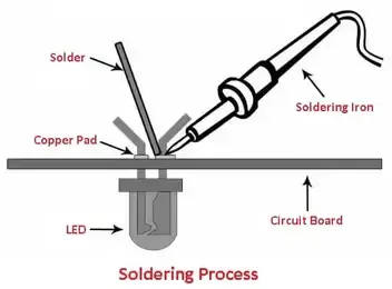
SOLDERING: Soldering is a process in which two or more metal items are joined together by melting and then flowing a filtered metal into the joint – the filter metal having a relatively low melting point. Soldering is used to form a permanent connection between electronic components.
ADHESIVE JOINING:
Adhesive bonding is a process in which joining between two or more parts is accomplished by the solidification or hardening of a non–metallic adhesive material.
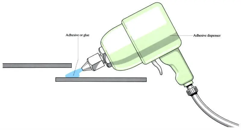
These are of several types in which some are described below
SOLVENT JOINING: Solvent welding, also known as solvent cementing or solvent bonding, is the process of joining articles made of thermoplastic resins by applying a solvent capable of softening the surfaces to be joined, and pressing the softened surfaces together. Pipe and fittings are bonded together by means of chemical fusion.
WATER BORNE JOINING: Waterborne Polyurethane Dispersions (PUDs) are coatings and adhesives that use water as the primary solvent.
HOT MELT: Hot melt adhesive (HMA), also known as hot glue, is a form of thermoplastic adhesive that is commonly sold as solid cylindrical sticks of various diameters designed to be applied using a hot glue gun.
Question No:- 3. What is Resistance Welding & its application in the automotive sector?
Answer:-
RESISTANCE WELDING
Resistance welding can be defined as; it is a liquid state welding method where the metal-to-metal joint can be formed within a liquid state otherwise a molten state. This is a thermoplastic method where heat can be generated at it is a thermo-electric process in which heat is generated at the edge planes of welding plates because of electric resistance and a weld joint can be created by applying low-pressure to these plates. This type of welding uses electric resistance to generate heat. This process is very efficient with pollution-free but the applications are limited because of the features like equipment cost is high, and material thickness is limited.
WORKING PRINCIPLE:
The working principle of resistance welding is the generation of heat because of electric resistance. resistance welding such as seam, spot, and projection works on the same principle. whenever the current flows through electric resistance, then heat will be generated. the same working principle can be used within the electric coil. the generated heat will depend on materials resistance, the applied current condition of a surface, applied the current time period.
This heat generated takes place because of the energy conversion from electric to thermal. the resistance welding formula for heat generation is,
H=l2RT
H is a generation heat, and the unit of the heat is the joule.
I is an electric current, and the unit is ampere.
H is a generation heat, and the unit of the heat is joule.
H is a generation heat, and the unit of the heat is joule.
H is a generation heat, and the unit of the heat is joule.
R is an electric resistance, and the unit is ohm.
T is the time flow, the unit is second.
TYPES OF RESISTANCE WELDING
SPOT WELDING:
Spot welding is the simplest type of welding where the work portions are jointly below the force of the anvil face. the copper electrodes will make contact with the work portion & the flow of current through it. the work portion materials apply a few resistances within the current flow which will cause limited heat production. the resistance is high at the edge surface because of the air gap. the current begins to supply through it, then it will reduce the edge surface. the current supply & the time must be enough for the correct dissolving of the edge. now the flow of current will be stopped however the applied with electrode continued for a second, whereas the weld quickly cooled. later, the electrodes were eliminated as well as getting in touch with a new spot to create a circular piece.
the piece size mainly depends on electrode size (4-7mm)
SEAM WELDING:
This type of welding is also known as continuous spot welding whereas roller form electrodes can be utilized to supply current throughout work parts. initially, the electrodes are getting in touch with the work part. high current can be supplied through these electrode rollers to melt the edge surface & shape a weld joint. at present, the electrode rollers will begin rolling on work plates to make a permanent weld point. the weld timing & electrode movement can be controlled to guarantee that the weld overlap & work doesn't acquire to the arm. the speed of the welding can be about 60 in per min within seam welding, which is used to make airtight joints.
PROJECTION WELDING:
Projection welding is similar to spot welding apart from a dimple that can be generated on work parts at the place wherever weld is preferred. At present, the work parts are held among electrode as well as a huge quantity of current flow through it. A little quantity of the pressure can be applied throughout the electrode on welding shields. the flow of current throughout the dimple which dissolves it & the force reasons the dimple level & shapes a weld.
FLASH BUTT WELDING:
Flash butt welding is a form of resistance welding, used for welding tubes as well as rods within steel industries. in this method two parts are welded which will be held tightly during the electrode holders as well as a high pulsed flow of current within the 100000-ampere range can be supplied towards the work part material, in the two electrode holders one is permanent & other is changeable. At first, the flow of current can be supplied & changeable clamp will be forced against the permanent clamp because if they get in touch with the two work parts at a high current the spark will be generated. whenever the edge surface approaches into plastic shape, the flow of current will be stopped as well as axial force can be improved to create jointly. in this method the weld can be formed because of plastic deformation.
APPLICATION:
- Resistance welding is widely used in the automotive industry.
- projection welding is widely used in the production of nuts and bolts.
- seam welding is used to produce leak-proven joints required in small tanks and boilers.
- flash welding is used to welding pipes and tubes.
ADVANTAGE:
- it can weld thin (0.1mm) as well as (20mm) metals.
- high welding speed.
- easily automated.
- both processes are simple and fully automated so does not require highly skilled labor.
- high production rate
- it is an environment-friendly process.
- it does not require any filter metal, flux or shielding gases.
DISADVANTAGE:
- high equipment cost.
- the thickness of the workpiece is limited due to the current requirements.
- It is efficient for high conductive materials.
- High electric power required
Question No:- 4. What is fusion welding & types of fusion welding with its application in the automotive sector?
Answer:-
FUSION WELDING:
fusion welding is a process that uses to join or fuse two or more materials by heating them to melting points. the process may or may not require the use of filler material. external application of pressure is not required for fusion. welding processes, except for resistance welding where substantial contact pressure is required during welding for sound joining. fusion welding processes can be grouped according to the source of the heat, for example, electric arc, gas, electrical resistance, and high energy.
TYPES OF FUSION WELDING
ARC WELDING:
Arc welding is a type of welding process using an electric arc to create heat to melt and join metals. A power supply creates an electric arc between a consumable or non-consumable electrode and the base materials using either direct (DC) or alternating (AC) currents.
Arc welding can use either direct or alternating current and uses consumable or non-consumable electrodes coated in flux the temperature in arc welding gets up as high as 6500 degrees Fahrenheit. some of the most common uses for arc welding include steel erection heavy equipment repair, pipelines welding, and many major construction projects.
APPLICATIONS:
Arc welding is widely used for chassis parts because of advantages such as the ease of continuous joining to secure high strength and rigidity of joints and wide freedom of joint shape to allow easy joining to pipes, brackets, or other accessories.
Many industries use GTAW for welding thin workpieces, especially nonferrous metals. it is used extensively in the manufacture of space vehicles and is also frequently employed to weld small-diameter, thin-wall tubing such as those used in the bicycle industry uses for arc welding include steel erection, heavy equipment repair, pipelines welding, and many major construction projects.
METAL INERT GAS (MIG) AND MRTAL ACTIVE GAS (MAG) WELDING:
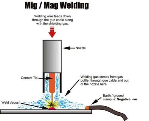
MIG welding is an arc welding process in which a continuous solid wire electrode is fed through a welding gun and into the weld pool, joining the two base materials together. Shielding gas is also sent through the welding gun and protects the weld pool from contamination. The MIG stands for metals inert gas. the technical name for it is gas metal arc welding (or GMAW) and the slang name for it is wire welding.
APPLICATION:
- Used for most types of sheet metals welding
- fabrication of pressure vessels and sheet structure
- Automotive industry and home improvement industry
TUNGSTEN INERT GAS WELDING (TIG):
TIG welding uses the heat generation by an electric arc struck between a non-consumable tungsten electrode and the workpiece to fuse metals in the joint area and produce a molten weld pool. The arc area is shrouded in an inert or reducing gas shield to protect the weld pool and non-consumable electrode. The process may be operated autogenously, that is without filler may be added by feeding a consumable wire or rod into the established weld pool. TIG produces very high-quality welds across a wide range of materials with thickness up to about 8 or 10mm it is particularly well suited to sheet materials.
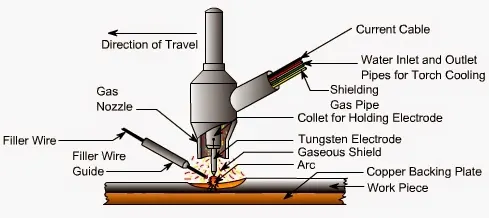
APPLICATION:
- TIG is most commonly used to weld thin sections of stainless steel and non-ferrous metals such as aluminum, magnesium, and copper alloys.
- one of the advantages of TIG welding is making rust-resistant metal fusion. The ability applied in the automobile industry to avoid rusting of crucial vehicle parts. Additionally, it strengthens the bond making it tough and therefore safer.
PLASMA ARC WELDING:
plasma arc welding is very similar to TIG as it the formed between a pointed tungsten electrode and the workpiece. however, by positioning the electrode within the body of the torch, the plasma arc can be separated from the shielding gas envelope plasma is the force through a fine-bore copper nozzle that constricts the arc. The PAW (plasma arc welding) method is related to GTAW(Gag tungsten arc welding) this arc welding can be formed among the metal as well as an electrode. The major difference between the PAW & GTAW is that in PAW the welder is capable of placing the electrode in the touch's body; so this will allow the PAW to be divided from the protecting gas.
APPLICATION:
- it is mainly used to fix tools, mold, and die.
- it is used to coating otherwise welding on the turbine blade.
- it is used to join stainless tubes and pipes
SUBMERGED ARC WELDING:
Submerged arc welding is one type of welding method where arc can travel under a layer of granular flux. In this type of welding, a tubular electrode otherwise consumable solid can be fed constantly to the region. At the same time, a layer of granular fusible flux can be poured over the weld zone which immersed the welding arc as well as defends it from atmospheric pollution.
APPLICATION:
- The main application of submerged arc welding is carbon steel (structure & vessel construction)low alloy.
FLUX-CORED ARC WELDING:
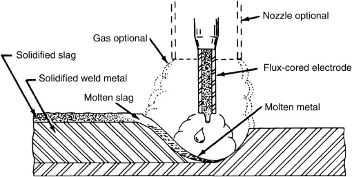
Flux-cored arc welding (FCAW or FCA) is a semi-automatic arc welding process. it requires a continuously- fed consumable tubular electrode containing a flux of a constant -voltage or, less commonly, a constant-current welding power supply. An externally supplied shielding gas is sometimes used, but often the flux itself is relied upon to generate the necessary protection from the atmosphere, producing both gaseous protection and liquid slag protecting the weld. the process is widely used in construction because of its high welding speed and portability.
Question:- 5. What is the 3-2-1 principle?
Answer:
The 3-2-1 principle of location principle is used to contain the movement of the workpiece along with the three-axis XX, YY, ZZ. this is achieved by providing six locating points, 3 pins in the base plane, 2 pins in the vertical plane, and 1 pin a pin which is perpendicular to first two planes.
it is known as the SIX point location principle. In this, the three adjacent locating surfaces of the blank (workpiece) are resting against 3,2 and 1 pins respectively, which prevent 9 degrees of freedom. the rest three degrees of freedom are arrested by three external forces usually provided directly by clamping. the 3-2-1 principle states that the six locators are sufficient to restrict the required degree of freedom of any workpiece. This motion is restricted using clamps and locators. A three-pin base can restrict five motions and six pins restrict nine motions.
METHODOLOGY OF THE 3-2-1 PRINCIPLE:
for this refer to the below images,
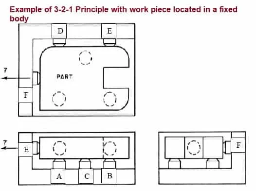
- The workpiece is resting pins A, B &C which are inserted into the base of the fixed body.
- The workpiece can't rotate about the axis XX, YY, and also can't move downward.
- In this way, the five degrees of freedom 1,2,3,4 & 5 have been arrested.
- Two pins D and E are inserted in the fixed body, in a plane perpendicular to the plane containing pins A, B & C.
- Now the workpiece can't rotate about the Z-axis and also it can't move towards the left.
- Hence the addition of pins can't D and E restrict three more degrees of freedom, namely 6, 7and 8.
- Another pin F in the second vertical face of the fixed body arrested degree of freedom 9.
The above method of locating a workpiece in a fixture is called the 3-2-1 principle.
LOCATING PROCESS:
We have two objectives when mounting a part in a fixture for machining:
1. Accurately position the part at the desired coordinates.
2. Restrict all six degrees of freedom so that the part cannot move.
A widely used method of accomplishing these two objectives uses the 3-2-1 principle, so-called because it entails three steps that employ three, then two, then one fixed point of known location. Since that adds up to six fixed points, it’s also known as the six-point method.
In the three steps of the 3-2-1 method, three mutually perpendicular planes, called datum planes, are introduced, one at each step. These three planes define the workpiece position, and together with opposing clamping forces fully constrain the part. Let’s take a look at the details of the 3-2-1 method
The Locating Process: Degrees of Freedom
In order to completely specify the position in space of a three-dimensional
object (such as the cube that’s shown), we refer to six coordinates:
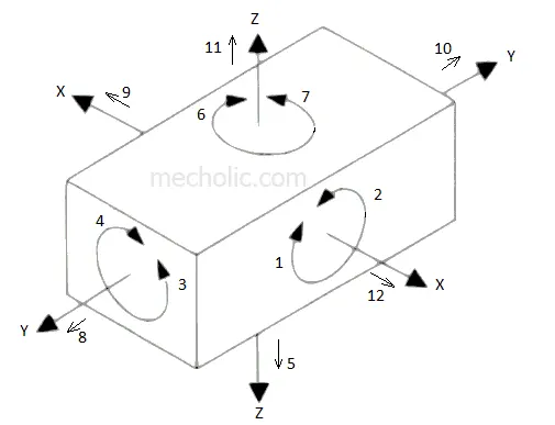
- Translational position along the X-axis
- Translational position along the Y-axis
- Translational position along the Z-axis
- Rotational position about the X-axis
- Rotational position about the Y-axis
- Rotational position about the Z-axis
These six coordinates are known as the six degrees of freedom of a three-dimensional object. As the double-headed arrows indicate, the translational and rotational positions can vary in either direction with respect to each of the three axes.
To completely prevent movement, all six degrees of freedom must be restricted.
The Locating Process: 3-2-1 Method
We have two objectives when mounting a part in a fixture for machining:
1. Accurately position the part at the desired coordinates.
2. Restrict all six degrees of freedom so that the part cannot move.
A widely used method of accomplishing these two objectives uses the 3-2-1 principle, so-called because it entails three steps that employ three, then two, then one fixed point of known location. Since that adds up to six fixed points, it’s also known as the six-point method.
In the three steps of the 3-2-1 method, three mutually perpendicular planes, called datum planes, are introduced, one at each step. These three planes define the workpiece position, and together with opposing clamping forces fully constrain the part. Let’s take a look at the details of the 3-2-1 method.
First Plane
Geometry tells us that three points are required to define a plane. This is the "3" in 3-2-1. So, three specific points are used to define the first plane. Fewer than three points cannot define a plane, and in the real world, dimensional tolerances mean that four or more points will not be coplanar. A real-world, less than ideally perfect part placed on four or more reference points will, in fact, rest on only three of the points due to its less than perfect surface. Different parts may rest on different combinations of three points, resulting in variation between finished parts. A stool can be used to illustrate this concept. A two-legged stool would certainly be unstable. A three-legged stool sits rock-solid. A four-legged stool is often found to rock. In the illustration, a three-dimensional part, represented by a cube, is placed on a datum plane defined by three support points. The part’s six degrees of freedom have now been reduced to three. It can still move along the X or Y axes, and it can still be rotated about the Z-axis. (The part cannot move along the Z-axis because it is held against the plane by clamping force.
Second Plane
A second plane, if it is perpendicular to the first, can be defined by two points, the "2" in 3-2-1. The part is now constrained to one degree of freedom: movement along the Y-axis. (The part cannot move along the X or Z axes because it is held against the planes by clamping force.)
Third Plane
A third plane, if it is perpendicular to both of the first two planes, can be defined by one point, the "1" in 3-2-1. The part is now entirely constrained. It cannot move along or rotate about the X, Y, or Z axes. (Remember that the part is held against each of the three planes by clamping force.)
Question No:- 6. Define the Body coordinate system?
Answer:-
CO-ORDINATE SYSTEM
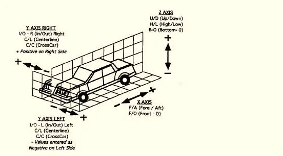
A coordinate system is a reference system consisting of a set of pipes, lines, and surfaces used to define the position in space either in 2 or 3 dimensions. In general, BCS is also known as a car line or body line.
BODY CO_ORDINATE SYSTEM
when locating the vehicle origin front whereas vehicle dimensions are taken from
- The x plane run from to back of the vehicle when viewed inside (front of vehicle pointing left)
- the plane runs from side to side of the vehicle (door mirror) when viewed in front, rear, or plan view.
- note the right-hand side of the vehicle is always positive y and the left-hand side of the vehicle is always negative y.
This is irrespective of the actual drive of the vehicle.
for vehicle development we use,
- x positive reward; origin at the front axle position
- z positive up; origin at a convenient position on the vehicle (on a structural frame perhaps, depending on the vehicle).
- y positive left; centered on the symmetry plane
- for the vehicle dynamics work, it is different
- x positive forward; origin at the front axle position
- z positive up; origin at the ground plane
- y positive right; centered on the symmetry plane.
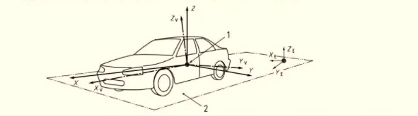
intermediate axis system
(X, Y, Z)
Axis system (2,3) whose X and Y axes are parallel to the ground plane (2,5), with the axis aligned with the
vertical projection of the x, axis onto the ground plane (2,5)
see figure 1.
Note 1: for multi-unit combination, a separate intermediate system may be defined for each vehicle unit (3,1)
Note 2: the intermediate axis system is used to facilitate the definition of angular orientation .... and the components of
force moment and vector an intermediate coordinate system is not defined
Question No:- 7. Elaborate Body plane system & its essentials.
Answer:-
BODY PLANE COORDINATE SYSTEM:
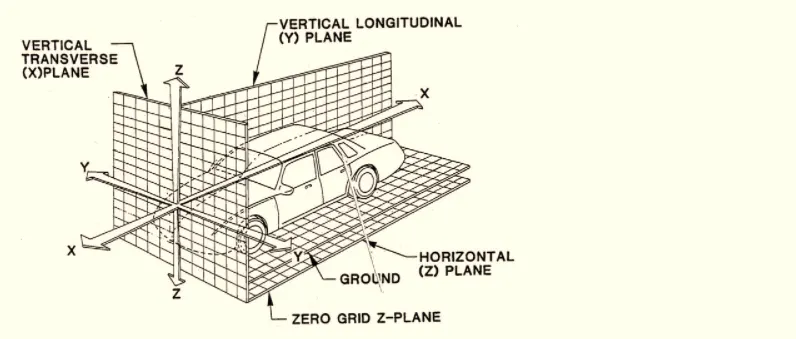
A VEHICLE'S (Motion) degrees of freedom are named as in marine and aerospace engineering, such as heave, roll, pitch, and yaw, see figure 1-5, figure 1-5 also defines the 3 main geometrical planes, such as transversal plan and symmetry plan.
For ground vehicles, the motion in the ground plane is often treated as the primary motion, which is why longitudinal, lateral, and yaw are called in-ground-plane degrees of freedom. The remaining degrees of freedom are referred to as out-of-ground-plane.
Vehicle (motion) degrees of freedom and important planes. The consistent use of parameters that describes the relevant
positions, velocities, accelerations, forces, and moments (torques) for the vehicle is critical. Unfortunately, there are
sometimes disparities between the nomenclature used in different textbooks, scientific articles, and technical reports.
It is important to recognize which coordinate system is being applied and realize that all conventions will provide the same
results as long as the system is used consistently. Two predominant approaches are encountered: the international Standards. Organisation (ISO) and the Society of Automotive Engineers (SAE). Both ISO, (ISO8855), and SAE, (SAEJ670), are right-handed systems. Figure 1-6 shows the vehicle fixed coordinate systems for these two standards. This compendium uses ISO, which also seems to be the trend globally. The new edition of (SAEJ670) now also recognizes an optional ise of z-up.
ISO and SAE coordinate systems The distinction between vehicle fixed and inertial (= earth fixed = world fixed) coordinate systems is important. The inertial, vehicle, wheel corner, and wheel reference frames. All these different coordinate systems allow for
the development of equations of motion in a convenient manner.
Coordinate systems and motion quantities in the ground plane The orientation of the axes of an inertial coordinate system is
typically either along with the vehicle directly at the beginning of a maneuver or directed along the road or lane.
Road or lane can also be curved, which calls for a curved longitudinal coordinate. The origin of a vehicle's fixed coordinate system is often the center of gravity of the vehicle, but other points can be used, such as the mid-front axle, mid of front bumper, and the outer edge of the body with respect to the certain obstacles, etc. Positions often need to be expressed for the center of the lane, road edge, another moving vehicle, etc. Body planes are three imaginary perpendicular planes. These are reference planes in the automotive car. The measurement from body plane to dimensions is called body plane dimensions.
ESSENTIALS OF BODY PLANE DIMENSIONS:
1. It defines the exact position of each product in the vehicle with respect to a fixed origin.
2. It ensures flawless design for assemblies.
3. While designing lines, all the designs are carried out relative to the body lines.
4. It assists in the easy location of different parts in the vehicle.
5. It aims in creating a standardized system.
6. It assists in quality checks
Thanks.