Week 2:- BiW Fixture Basics Challenge
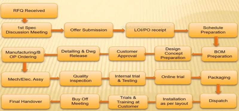
1) What is the process of project execution activity?
Project execution activity refers to all the activites in any project that will have the list of the steps involved in creating the final product from start to finish. There are many steps involved in a project activity execution, these steps are explained in more detail below
- RFQ:
RFQ is the request for quotation which will be a document that contains the basic requirements for the customer. This data will be used to further study and evaluate the technical and commercial offer along with the tentative timeline.
- 1st Spec Discussions Meeting:
The 1st spec discussion meeting is where the RFQ is studied and the documents for the technical and commercial offer are prepared by the company along with their suggested timeline.
- Offer Submission
This offer that is drawn up by the company is then submitted to the customer for his review and approval and if the given offer which contains the commercials and the timelines are acceptable for the customer.
- LOI/PO Receipt
Once the customer has compared the offers submitted by the different potential companies that can produce the product from him, he chooses the offer that suits his/her requirement and then releases the Purchase Order or the PO receipt to that manufacturer.
- Schedule Preparation
This stage consists of breaking down all the activities that would be required to complete the production of the final product and preparing a timeline for each of the activities.
- BOM Ordering
BOM ordering refers to the purchase of all consumables required for the production of this component. The consumable includes items such as grease, oil etc. This is also the stage where the parts that are not manufactured but rather bought as such from the third-party vendors are done.
- Design Concept Preparation
This is the stage where the concept for the model is built by the manufacturer. The basic input 3D and 2D data will be provided by the customer in the purchase order release and based on this a concept is prepared and sent to the customer for approval.
- Customer Approval
The concept design that was prepared in the previous stage is now sent to the customer for approval and the customer will verify if his/her design inputs were followed and if the manufacturer has satisfied all the requirements and if all this checks, then the customer gives the green signal to go ahead with the production and if not, then customer will give the required changes to be made to the manufacturer.
- Detailing and Drawing Release
In this stage the product is broken down into its child components and detailed drawings containing all the required information is created. For parts that are outsourced from vendors the drawings for the respective components are obtained from the vendor.
- Manufacturing/BOP Ordering
Once the drawings have been released, it is passed on to the manufacturing team who will go ahead with the manufacturing of the various units and will also be placing the orders for the other components such as the cylinders and sensors as per the required specifications.
- Mechanical/Electrical Assembly
After all the components have been manufactured, it will be passed to the quality control team for inspection and if they give the okay to go ahead then only the assembly of the components is done. This assembly will be done as per the drawings released by the design team so that it adheres to the required specifications.
- Quality Inspection
A second round of quality inspection is conducted once the components have been assembled and the final product has been assembled. The quality inspection team will check if it is as per the final drawing provided and will check if all the dimensioning and the coordinates are proper or not. The CMM will also be used to check if all the relative dimensions are okay. Once the assembly is CMM and Quality approved, we move to the next stage.
- Internal Trial and Testing
In internal trial and testing, the assembly is placed on the fixture to check if the fixture is holding the assembly as required and if it is properly fixed to ensure that the pins are slotting into the holes correctly and if the clamping is done right on the assembly. Post this the trials are done, to see if the welding can be done with no issues arising.
- Online Trial
Online trial is nothing but automating the process and running a trial on it to check once automated to see if everything is working in the right sequence as required.
- Packaging
Once the online trial is completed and the customer has approved it, the fixture moves to the packaging stage where the fixture is packaged with the utmost care to ensure that it is not damaged or hampered during transportation.
- Dispatch
Dispatch is nothing but the logistics involved to the get fixture from the manufacturer to the customer.
- Installation as Per Layout
A layout is designed at the very beginning of the manufacturing process to define where and how the fixture will be mounted, where the robot will be mounted, the distance between robot and fixture is defined. This is done so as to be able to install the fixture properly and to ensure the working of it also is proper.
- Trials and Training at Customer
This is the final trial done, this trial happens at wherever the customer has asked to assemble the fixture. This trial is done in front of the customer to show that to ensure that everything is working as promised and alongside this procedure, the training of the operators is also conducted to properly educate them on how to go about the working of these fixtures.
- Buy Off Meeting
The buy off meeting is the stage where the customer gives his final approval or if any changes have to be made or any additional modification has to be done, it is conveyed in this stage and once all the required changes have been made we move to the final stage.
- Final Handover
The final handover is the final stage in the manufacturing process where the complete order or part of the order of the fully approved product is manufactured and delivered to the customer.
2) What are the types of joining processes?
Joining is one of the manufacturing processes where 2 or more materials can be permanently or temporarily joined together to form a single unit.
The durability and the performance of any structure is largely dependent on the quality and design of the joints.
The two fundamental options for joining materials are:
- Mechanical Joining
- Metallurgical Joining
Metallurgical Joining Process
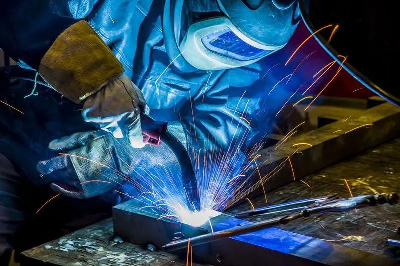
Welding: Welding is a fabrication process where two or more parts/components are fused together with the application of an external agent like heat, pressure or both forming a joint as the parts cool. Welding is usually used on metals and thermoplastics. Some materials require the use of specific processes and techniques.
The parts that are joined are known as the parent materials. The material added to help form the joint is called filler or consumable. Consumables are usually chosen to be similar in composition to the parent material, thus forming a homogenous weld, but there are occasions, such as when welding brittle cast irons, when a filler with a very different composition and, therefore, properties is used. These welds are called heterogeneous welds.
In welding, there are various methods to go about the welding process and based on these methods welding is subdivided into 4 main types which are, MIG Welding, TIG Welding, Gas Welding, Plasma Arc Welding and Electron Beam and Laser Welding.
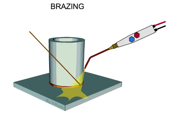
Brazing: Brazing is a metal joining process in which 2 or more materials are joined together by melting and flowing a filler metal into the required joint. The filler used in brazing will always have a much lower melting point than the materials it is supposed to join. This is obviously done so that the parent material does not melt when trying to melt the filler material.
Brazing is used to close the gap between very close fitting parts as the filler metal flows into this gap by the application of capillary action.
Brazing differs from welding as it does not involve melting of the parent material. Brazing is also advantageous in the fact that it can be used to join very dissimilar metals and also work pieces of varying thickness can be joined together.
There are many types of brazing and the few commonly used ones are Torch Brazing, Furnace Brazing, Vacuum Brazing and Silver Brazing.
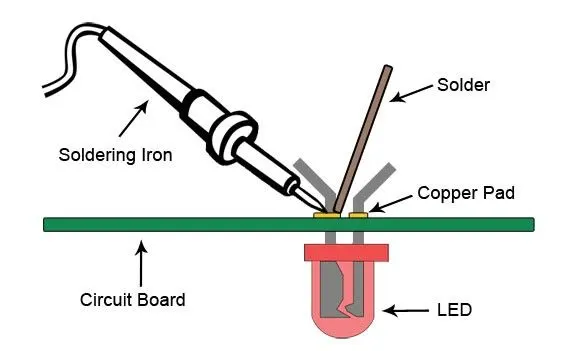
Soldering: Soldering is a process used for joining metal parts to form a mechanical or electrical bond. Typically a filler or solder in this case, with a low melting point is used and this is melted and applied to the required material which then forms the bond once the material solidifies and similar to brazing and unlike welding, in soldering the filler material will have a lower melting point temperature than the parent material.
Soldering is mostly used in electrical application but it is seen in plumbing and for automotive sheet metal components as well.
Chemical Joining Process
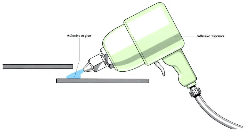
Adhesive Bonding: Adhesive bonding is a joining technique used in manufacturing where the components are bonded together using adhesives. An adhesive can be defined as a substance that causes 2 surfaces to stick together. Adhesive bonding has many advantages as compared to the previously mentioned metallurgical joining techniques such it does not cause any distortion on the metal surface like welding does, it does not need the surface to be damaged by drilling holes for example, it can be used on dissimilar metal substrates with differing melting point and also the fact that its add weight negligibly to the final assembly as compared to the other methods.
Mechanical Joining Process
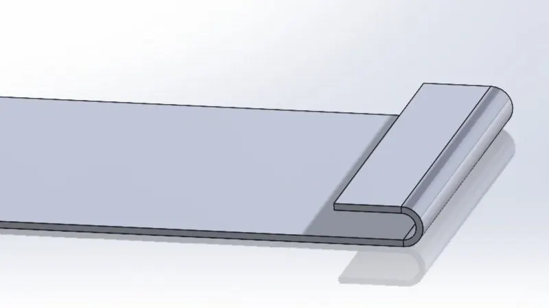
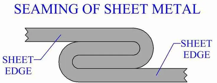
Hemming and Seaming: Hemming and Seaming are similar mechanical joining processes but vary in the way it is done, hemming is a process where the sheet metal edge is rolled flushed to itself whilst in seaming, the edges of 2 materials are joined together.
Hemming is usually done when it is a material whose aesthetics cannot be ruined by processes such as welding which would lead to marks and distortions on the outer surface. Hemming can also be done to smoothen out rough edges or to reinforce an edge of the material.
Seaming is done to join two materials together and this can be observed in the roof panel of a car, another application where seaming is widely used is in the canned food industry.
The process of hemming and seaming is mostly similar except for the external force applied during this process and seaming requires a much larger force than hemming.
The images below depict the process of hemming (image on the left) and the seaming (image on the right)
Mechanical Fasteners: A mechanical fastener is a device that is typically used to join two or more materials together. Mechanical fasteners are of two types, permanent and non permanent.
The non-permanent fasteners, as the name suggests, can be used to join materials together and when not needed can be removed from the workpiece and this would result in the separation of the joining materials without affecting them physically.
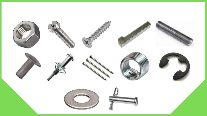
Typical examples of non-permanent mechanical fasteners are Screws, Bolts, Nuts and Washers.
A permanent mechanical fastener is a way of joining 2 or more materials together permanently, which means unlike the previous type of fasteners, these cannot be removed so easily and even if they are removed from the joining material, they tend to damage it and will render the workpiece defective. An example of a permanent mechanical fastener are rivets.
What is Resistance Welding and its application in the automotive sector?
Resistance welding is the process by which metals are joined together with the application of pressure and passing current through it for a certain period of time at the area of joining.
The advantage resistance welding has over the other forms of welding is that there is no requirement or need for using a filler material to form the bond and this makes the process very cost effective.
There are several variations of resistance welding and given below is a more detailed explanation on some of them:
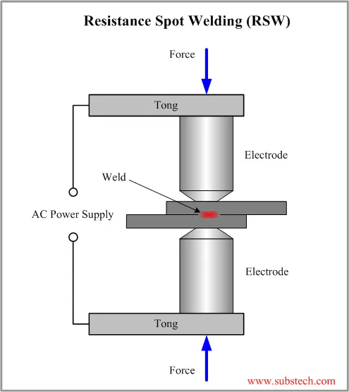
- Spot Welding: Like all resistance welding process, the spot-welding method creates a weld by making use of the heat generated by the resistance to the flow of welding current between the joining materials. Resistance spot welding uses the face geometries of the welding electrodes themselves to focus the welding current at the desired weld location and also this helps to apply the required force to the joining materials. Once sufficient resistance is generated, the materials settle down and combine and the weld nugget is formed.
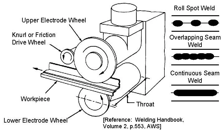
- Seam Welding: Resistance seam welding is a subset of resistance spot welding, but the difference here being instead of using the electrodes to focus on a single point on the material, here we use a wheel shaped roller as the electrode to provide the required force and welding currents to the work piece. The workpiece is rolls between the electrode rollers while the weld current is applied and depending on the this and the duration of the weld, we get overlapping welds which form a complete seam or it could alternatively form individual spot welds at defined intervals.
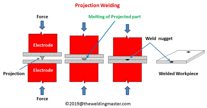
- Projection Welding: Projection welding uses the heat generated by resistance to the flow of the welding current as well as to the push the workpieces together applied over a defined period of time. Projection welding localizes the welds at predetermined points with the help of projections, embossments or intersections, which aids in focusing the heat generation at the point of contact. Once the weld current generated the required resistance at the point of contact, the projections collapse to form the weld nugget.
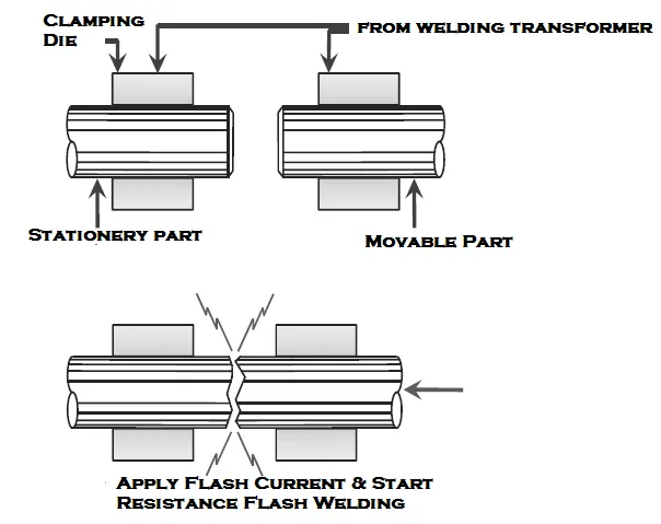
- Flash Welding: Flash welding is a form of resistance welding which generates resistance by taking advantage of the flashing action. This flashing action occurs when high current density is passed through very small contact points between the workpieces. At predetermined points after the flashing process has begun, the required force is also applied to the material and they are moved together at very controlled rate.
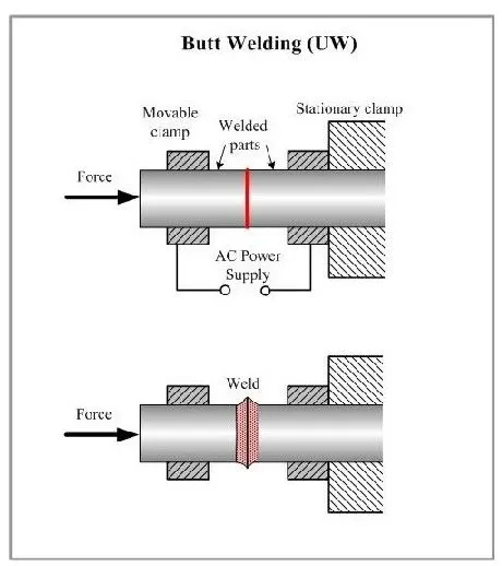
- Upset Welding: Upset welding is a form of resistance welding which is very similar to Flash Welding. Whilst similar to flash welding, in upset welding the workpieces are already in firm contact with each other and hence the flashing does not occur. The necessary pressure is applied before the current is started and this is maintained until the process is complete.
Application of Resistance Welding in Automotive Sector
Resistance welding is a widely used method in the automotive sector to join components together. Welds are mostly used to join the various sheet metal panels together and they are especially used when it comes to the joining of the panels that do not make up the class-A surface, or the surface that is seen by the end customer, because the process of joining the panels with a method like welding will cause distortion of the surface due to the welding process.
The roof is a prime example of a component that is welded by the one or more of the resistance welding methods. The body panels of a vehicle when it is in the Body-In-White stage is mostly joined using some form of resistance welding.
4) What is Fusion Welding & types of fusion welding with its application in the automotive sector?
Fusion welding is a term that is used for welding processes that rely on the melting to join materials of similar compositions and melting points. A heat zone is created in the material due to the high temperature phase transitions that are inherent to these processes.
Fusion welding is further classified as:
- Shielded Metal Arc Welding (SMAW)
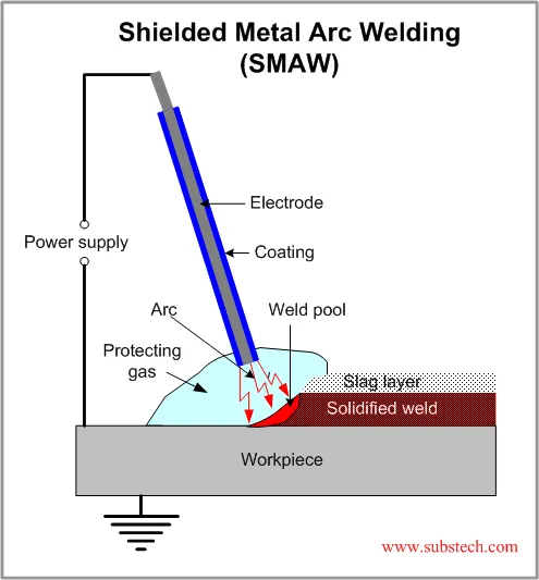
Shielded Metal Arc Welding (SMAW) is the most popular welding process and is also known as manual metal arc welding uses a metallic consumable electrode of a proper composition for generating arc between itself and the work piece. The molten electrode metal fills the weld gap and joins the materials.
The electrodes are coated with a shielding flux of a suitable composition. The flux melts together with the electrode metallic core, forming a gas and slag, shielding the arc and weld pool. The flux cleanses the surface and provides the weld some alloying elements while protecting the molten metal from oxidation and stabilizes the arc and once it is solidified the slag is removed.
- Metal Inert Gas Welding (MIG) and Metal Active Gas Welding (MAG)
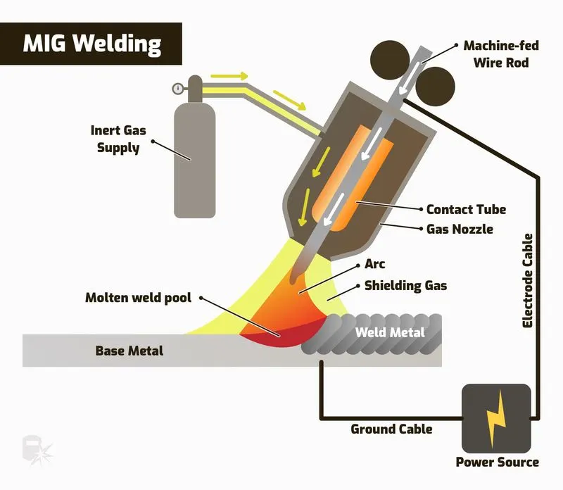
The MIG and MAG welding techniques refers to a form of fusion arc welding method that uses the heat generated by a DC electric arc to fuse the metal in the joint area. These welding methods use a protective gas shield. The protective shielding gas is used to protect the weld pool from unwanted contact with oxygen in the ambient atmosphere.
MIG and MAG welding are slightly different processes in respect with the gases that are used for the shielding process. In MIG welding, an inert, non-reactive gas is used for the purpose of shielding such as, Argon, Helium or a mix of both.
Whilst in MAG welding, the shielding gas used is carbon dioxide (CO2) or oxygen (O2) are added to the carrier argon gas as a shielding gas for the weld pool.
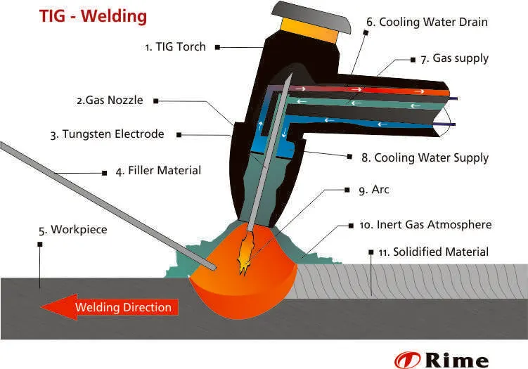
- Tungsten Inert Gas Welding (TIG)
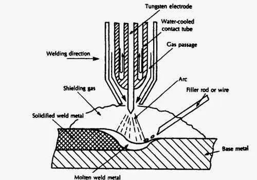
This is a welding method where a non-consumable tungsten electrode is used to produce a weld. An inert shielding gas like argon or helium is used to protect the weld area and the electrode from oxidation or other atmospheric contamination. This is the most commonly used to weld thin sections of stainless steel and non-ferrous metals such as aluminum, magnesium and copper alloys.
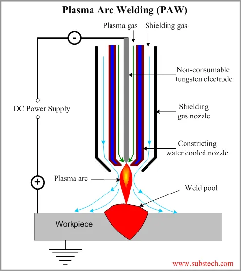
- Plasma Arc Welding (PAW)
Plasma arc welding is an arc welding process using heat produced by a compressed arc between a tungsten non consumable electrode and the workpiece. This is essentially an advanced form of TIG welding. Plasma arcs are formed using gas in two forms where one is laminar, that is it has a low pressure and low flow, and the second is a turbulent flow, where it has high pressure and high flow. The gases that are commonly used are helium, hydrogen or a mixture of these. In the case of plasma welding laminar flow is employed to ensure that the molten metal is not blown out of the weld zone.
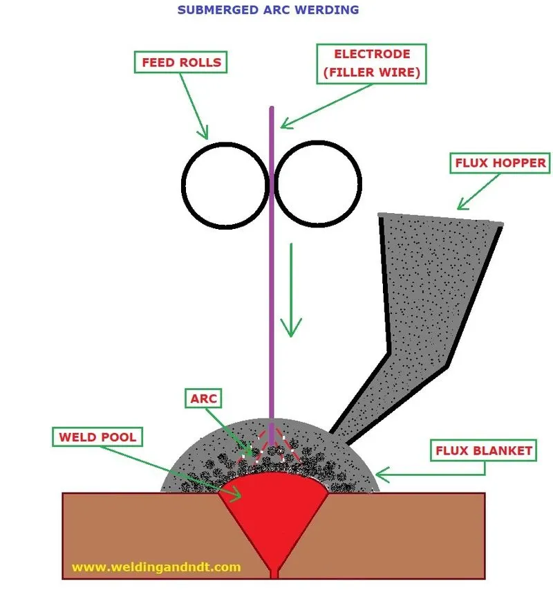
- Submerged Arc Welding (SAW)
This is another commonly used arc welding method that involves the formation of an arc between a continuously fed electrode and workpiece. A layer of powdered flux generates a protective gas shield and a slag which protects the weld zone. The submerged arc welding method does not require an additional protective shield gas and the reason for the name is because the arc is submerged beneath the flux blanket and is not normally visible during the welding process.
Application of Fusion Welding in Automotive Sector
- Arc welding is widely used in the automotive sector for the purpose for joining components of the chassis.
- TIG welding is used in the automotive industry because it is known to reduce corrosion over time at that point and hence car fenders are frequently welded using this method to avoid the formation of rust. TIG also has the advantage of being able to bond a varying selection of metals and hence is is extremely flexible to use. It can be used for welding non-ferrous metals like aluminum, copper, magnesium and stainless steel.
- MIG welding is used for many repairing components in the automotive sector. One reason for this is because MIG welding is a form of fusion welding that can be used regardless of the material or the thickness, it can be used effectively without sacrificing the strength of the weld or the overall appearance.
5) What is the 3-2-1 principle?
The 3-2-1 principle of location is used to constrain the movement of workpiece along the three axes XX, YY and ZZ. This is achieved by providing 6 locating points, 3 pins in base plate, 2 pins in the vertical plane and 1 pin in a plane which is perpendicular to the first two planes. The degree of freedom is the defines the ability of a body to move. Every body has 12 degrees of freedom or 12 possible movements and these twelve are broken down into 6 translational degrees of freedom and 6 rotational degrees of freedom. The 3-2-1 method is the fundamental principle for all types of fixture design.
Consider a body in a 3-axis coordinate system where we have the X, Y & Z as the respective axes. The image below shows the body in this coordinate system
From this we can infer that the 6 translational degrees of freedom are about:
+X, -X, +Y, -Y, +Z, -Z.
The 6 rotational degrees of freedom:
- Clockwise about X-axis (CROT-X)
- Anticlockwise about X-axis (ACROT-X)
- Clockwise about Y-axis (CROT-Y)
- Anticlockwise about Y-axis (ACROT-Y)
- Clockwise about Z-axis (CROT-Z)
- Anticlockwise about Z-axis (ACROT-Z)
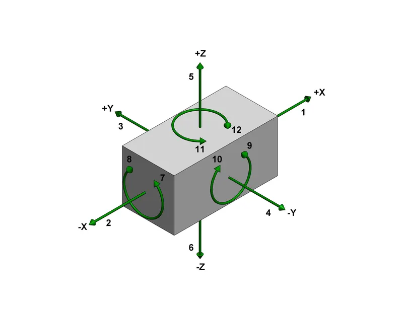
What this infers is that this body in space will have translational motion about any of the 3 mutually perpendicular axes in both directions and this provides the body with its 6 translational motions. The body can also rotate, clockwise or anticlockwise, about any of these 3 axes and this is what gives the body its 6 possible rotational motions.
We use locators, which are devices to establish and maintain the position of the workpiece properly to ensure that the work done it is accurate and repeatable.
The holding fixture used in an assembly operation often follow the 3-2-1 locating scheme to position parts. The first locators position a part in the primary plane, the next 2 locators then position the part in the secondary plane and final locators fixes the part in the tertiary plane and hence we lock the part in all its degrees of freedom.
The image below shows how the locators fix the part in all possible motion.
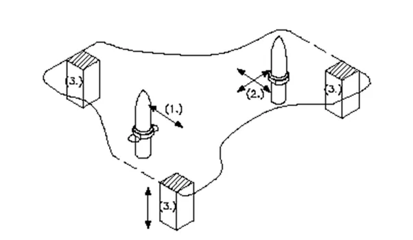
It can be observed in the image above that the 3-2-1 principle was followed to fix the workpiece. The first 3 pins placed at the bottom on the base plane (a plane parallel to the X & Y axis) restrict the rotation of the component about the X and Y axis. It also limits the downward movement of the component along the Z-axis.
The next 2 pins are in a plane parallel to the plane containing the X & Z axes. It prevents the rotation of the component about the Z axis and the movement of the body along Y axis in direction.
6) Define body co-ordinate system?
The body coordinate system has been widely used in the automotive industry for drawing of body parts, products and process design. In general, a coordinate system is a reference system consisting of points, lines and surfaces, which are used to define the positions of points in space in either two or three dimensions.
The body coordinate system is also called the car line or the body line. The origin of the body coordinate system is defined at the front center of the vehicle and it indicates the length of the car and the coordinate system (OZ) which is below the cars underbody, indicates the height of the vehicle and the coordinate system (OY) has its starting point at the center of the vehicle and this denotes the width of the vehicle. This a generalized approach to the body coordinate system and how it is drawn for a generic vehicle, in reality the origins for the various coordinate system could be at different points and this completely depends from manufacturer to manufacturer.
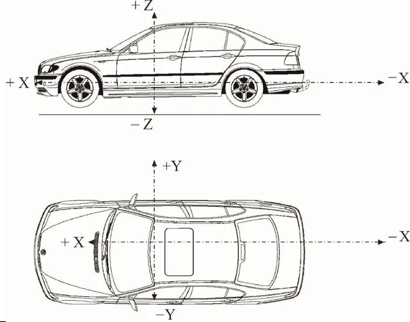
X = Longitudinal Direction [(Fore & After - F/A) or (Front O Line - FOL)]
Y = Transverse Direction [(Cross Car - C/C) or (Center O Line - COL)]
Z = Vertical Direction [(Up & Down - U/D) or (Bottom O Line - BOL)]
7) Elaborate Body plane system and its essentials.
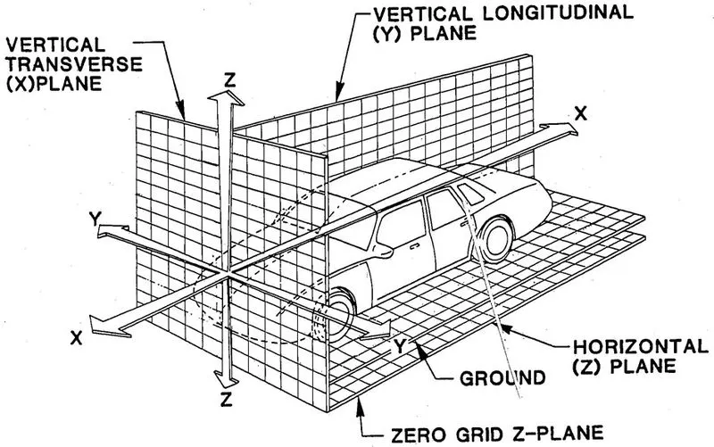
Body planes are 3 mutually perpendicular imaginary reference planes on the vehicle body and this helps to segregate the vehicle into sections. These planes are used to define the GD & T of all car parts in the automotive domain.
The measurements from the body planes to the parts are called as bodyline dimensions. These body planes are called as:
- FOL Front “O” Line
- COL Center “O” Line
- BOL Body “O” Line
- The measurement along FOL or X-axis is called as Front Aft (F/A)
- The measurement along COL or Y-axis is called as Cross Car (C/C)
- The measurement along BOL or Z-axis is called as Up Down (U/D)
The Bodyline dimensions are essential because:
- It ensures flawless design for the assembly
- While designing lines, all the design are carried out relative to the bodyline, ie, the fixtures, turntables etc.
- It assists in locating the various parts in a vehicle easily.
- It defines the exact position of each product in the vehicle with respect to a fixed origin.
- It assists in quality checks of the final product.