Week 2 Bevel Gear Challenge
BEVEL GEAR SIMULATION
OBJECTIVE
- To describe about the Grid Dependency test and its uses
- To perform Static Structural analysis on a Bevel Gear in ANSYS Workbench and perform Grid dependency test with three different mesh sizes
- Case 1: 6 mm as the element mesh size
- Case 2: 5 mm as the element mesh size
- Case 3: 4 mm as the element mesh size
Compare the results of Von-Mises stress, Total deformation and Equivalent Elastic Strain for three different cases.
1. GRID DEPENDENCY TEST:
The finite element mesh is used to subdivide the CAD model into smaller domains called elements, over which a set of equations are solved. These equations approximately represent the governing equation of interest via a set of polynomial functions defined over each element. As these elements are made smaller and smaller, as the mesh is refined, the computed solution will approach the true solution. The accuracy that can be obtained from any FEA model is directly related to the finite element mesh that is used .Mesh refinement is a very important factor for determining an accurate solution in FE analyses. In its simplest form, mesh refinement is the process of resolving the model with successively finer and finer meshes.
Mesh Refinement is also called as Grid Dependency Test or Grid Independent Test.
After comparing a set of solutions, an asymptotic behaviour of the solution starts to emerge, and the changes in the solution between meshes become smaller. Eventually, these changes will be small enough that we can consider the model to be converged.
Different Mesh Refinement Techniques
· Reducing the Element Size
· Increasing the Element Order
· Global Adaptive Mesh Refinement
· Local Adaptive Mesh Refinement
· Wavelength-Adaptive Mesh Refinement
· Time-Adaptive Mesh Refinement
and much more
2. MODEL SETUP
The 3D model of the setup is imported into ANSYS Space Claim. Check for any abnormalities in the Geometry.
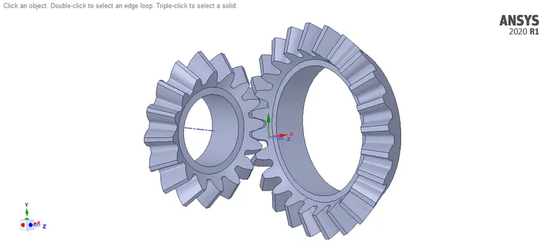
MATERIAL ASSINGMENT:
Structural Steel is used for both the gears
The properties of the materials used is shown below
- Structural Steel:
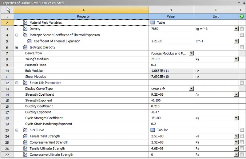
MODEL SETUP:
After importing the Geometry, rename the Parts and assign respective materials for different cases
CONTACTS DEFINITION:
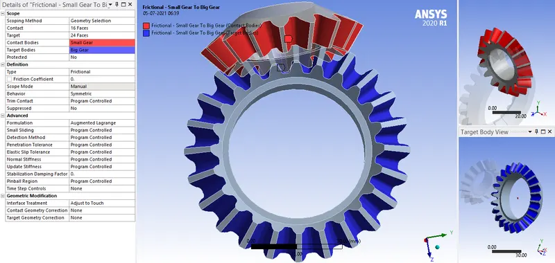
We need to define contact regions for this model. The settings are as shown below
- Frictional Contact is selected between the faces of the Gear tooth which will be in contact throughout the simulation.
JOINT DEFINITION:
We need to define joints for the model, they are
- A Revolute joint for the smaller gear :
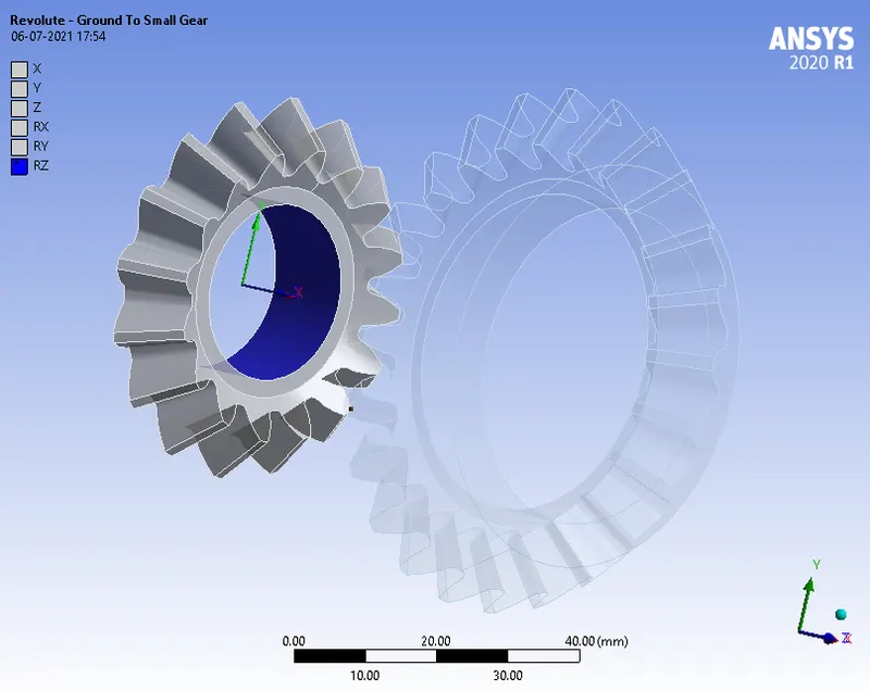
- A Revolute joint for the bigger gear :
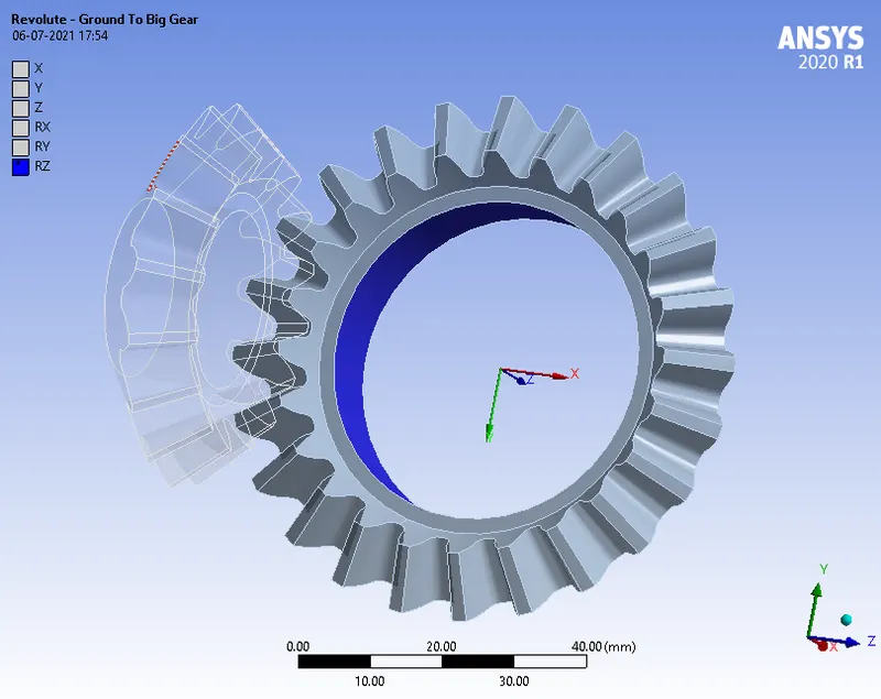
Also make sure the reference co-ordinate system assigned to the joint is as shown above.
MESHING:
The meshing is done as follows,
- A Patch Conforming Algorithm with Tetrahedrons method is assigned to both the gears
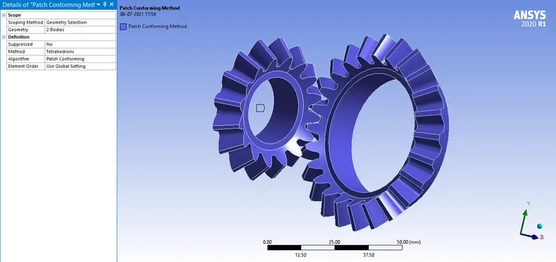
2. Face sizing of element size 1mm is selected between the faces of the Gear tooth which will be in contact
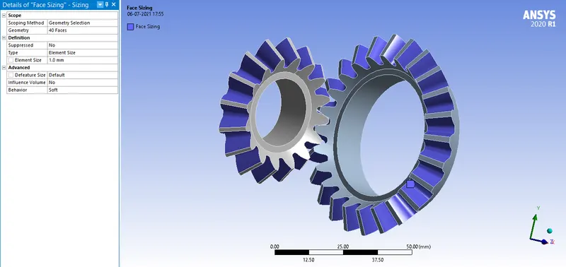
3.Mesh element size is selected for different cases as shown below
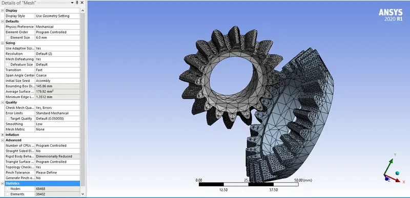
Case 1: Element size of 6 mm is assigned to both the Gears. The details and settings of the mesh are shown below.
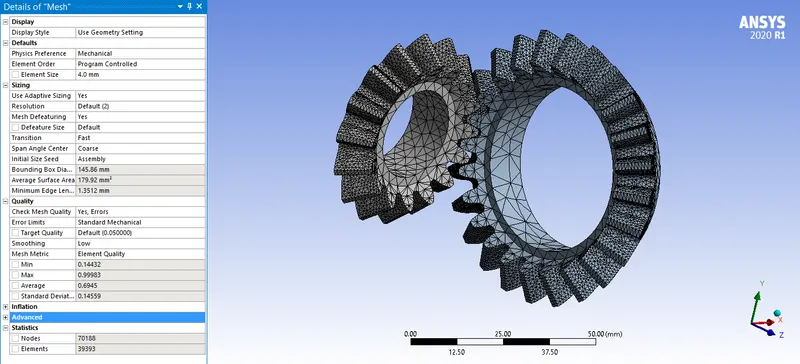
Case 2: Element size of 5 mm is assigned to both the Gears. The details and settings of the mesh are shown below.
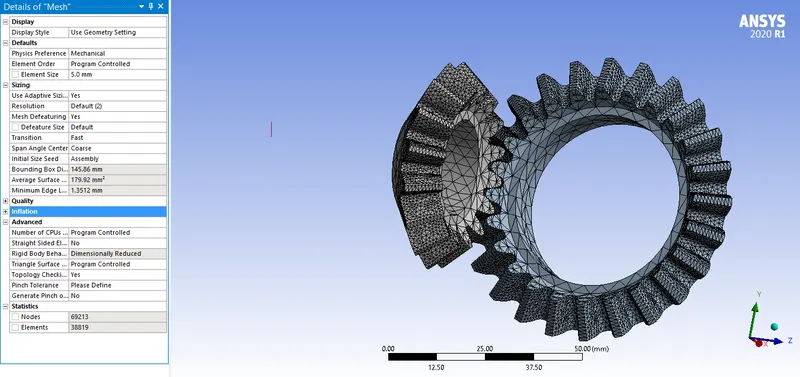
Case 3: Element size of 4 mm is assigned to both the Gears. The details and settings of the mesh are shown below.
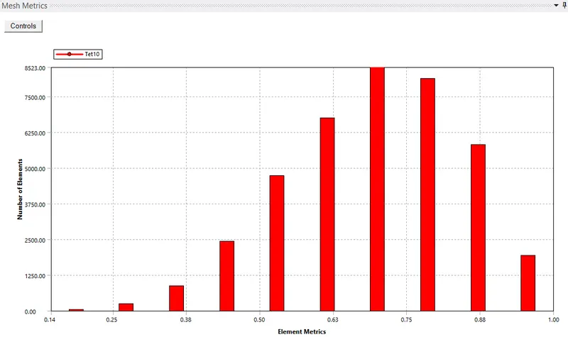
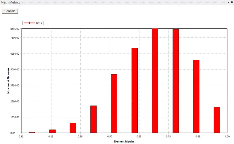
MESH QUALITY:
Case 1:
Case 2:
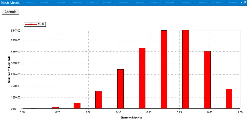
Case 3:
ANALYSIS SETTINGS:
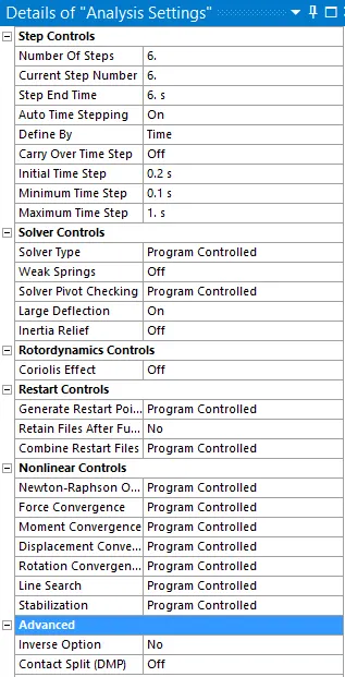
Now, the simulation is run for 6 steps. The following settings are modified
Auto Time stepping is set to ON and Time step values are assigned as shown below.
Solver Type is set to Program Controlled
Weak springs are set to OFF
The Large deflection is set to ON.
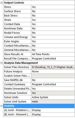
Other settings are as shown below
BOUNDARY CONDITIONS:
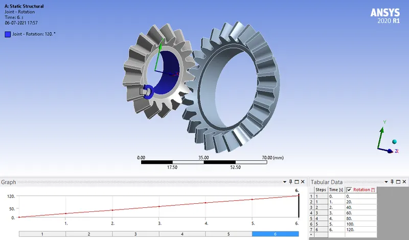
The boundary condition for this model are
- A Revolute Joint load of Rotation type is assigned to the Small Gear :
- A Revolute Joint load of Moment type is assigned to the Big Gear :
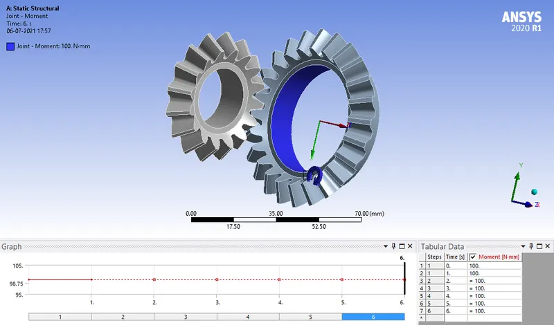
The values of the moment assigned are shown below
RESULTS:
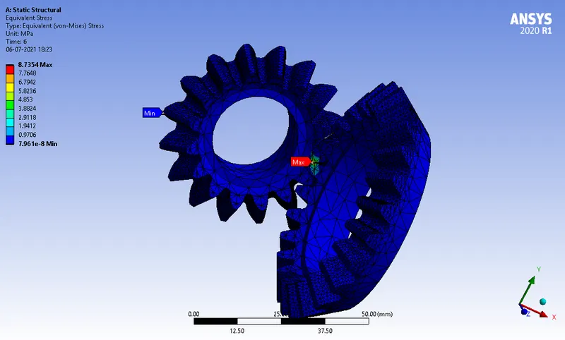
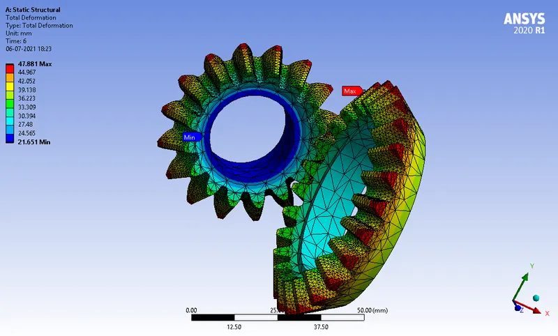
CASE 1:
ANIMATION:
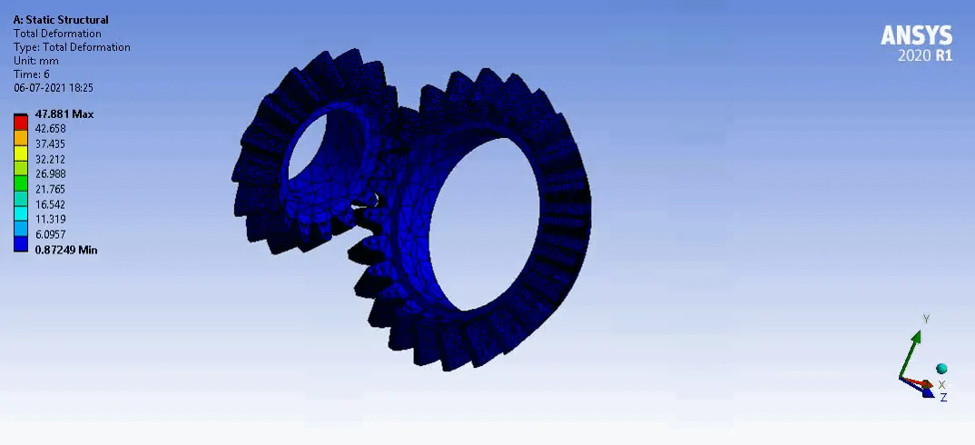
- Von-Mises Stress:
- Total deformation
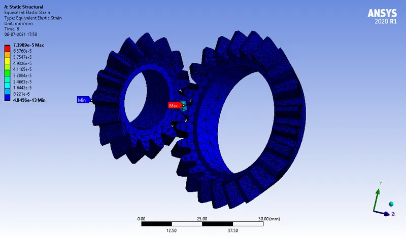
- Equivalent Elastic Strain
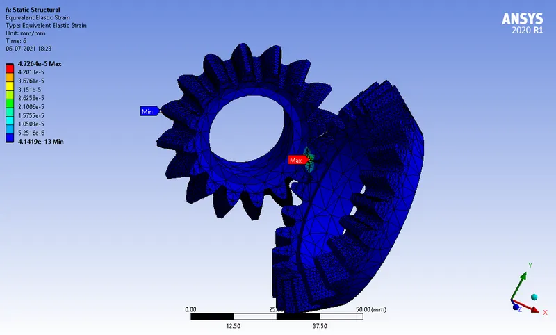
CASE 2:
ANIMATION:
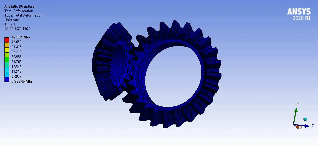
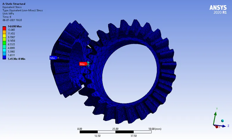
- Von-Mises Stress
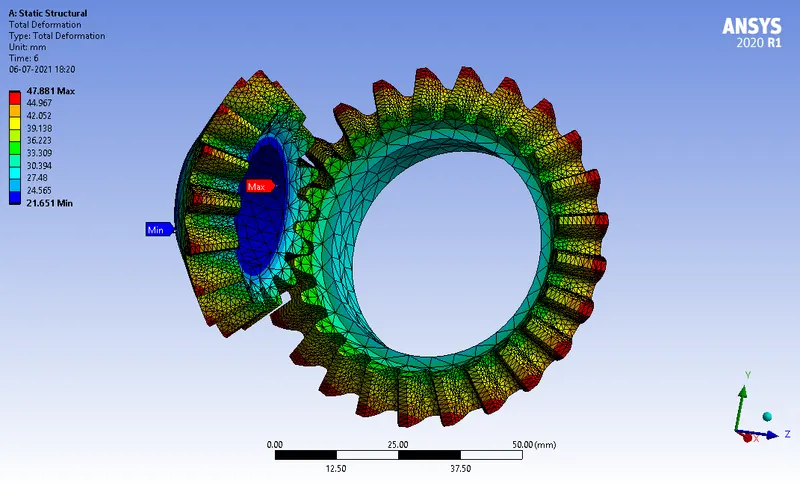
- Total deformation
- Equivalent Elastic Strain
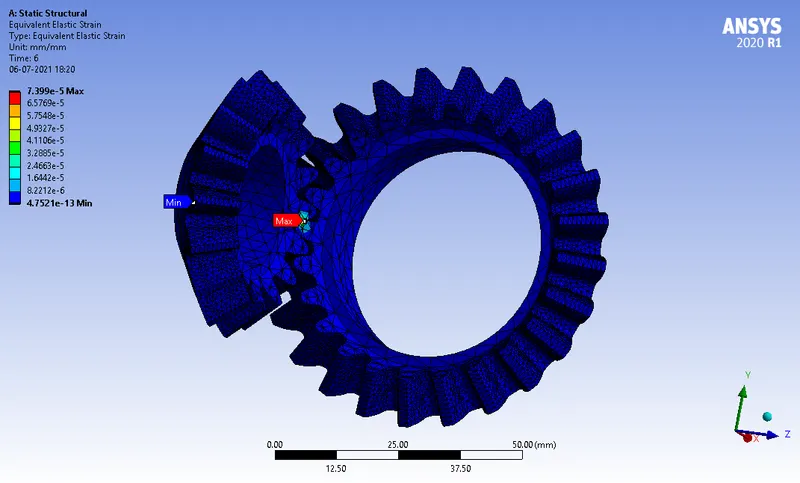
CASE 3:
ANIMATION:
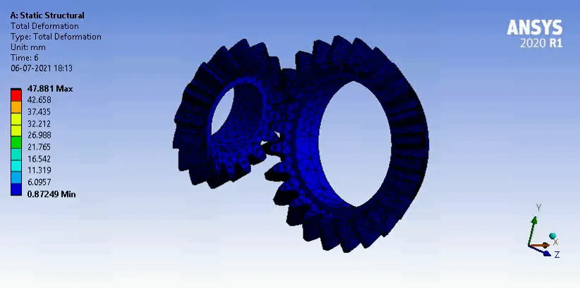
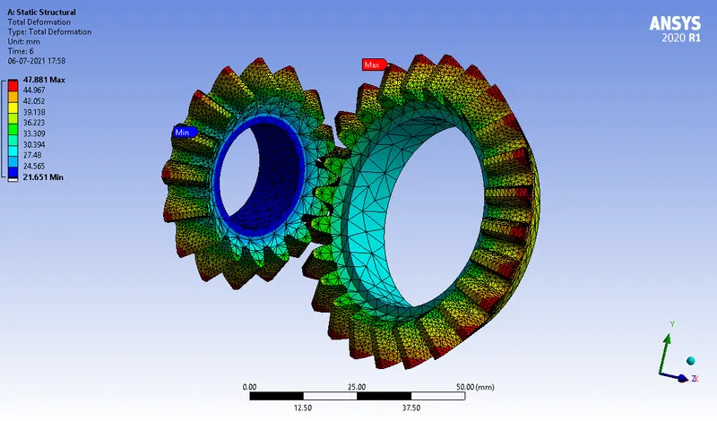
- Von-Mises Stress
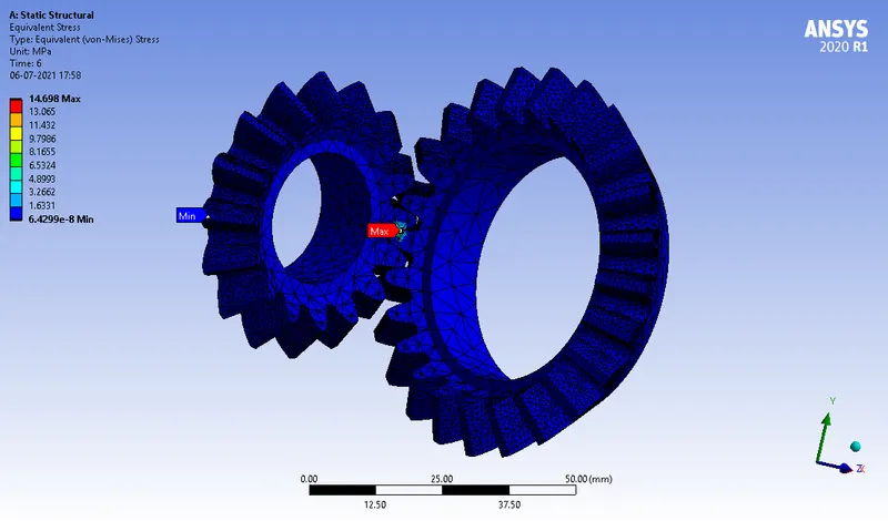
- Total deformation
- Equivalent Elastic Strain
CONCLUSION:
From the results, it can be inferred that
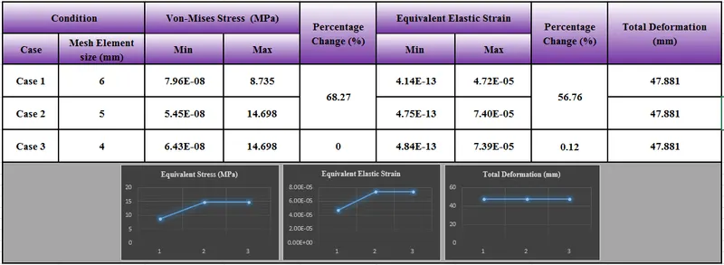
- Equivalent Stress and Strain both increased when mesh size was increased from 6 mm to 5mm and remains almost same when mesh size is furthur reduced to 4mm
- The accuracy of output results is increased when mesh size is decreased, because of finer mesh from coarser mesh
- Percentage change in the output values is very less for mesh element size of 5mm and 4mm. So, it is recommended to use 5mm as the mesh element size instead of 4mm mesh to reduce computational cost and time
- Furthur reduction in mesh size will only lead to increase in computational cost and time, but the results will remain almost same
Thus, Grid Dependency test have been performed in Bevel gear simulation
The simulation files are attached below