Week 2 Bevel Gear Challenge
GRID DEPENDENCY TEST FOR BEVEL GEAR SIMULATION
Aim:
1.To perform a Grid dependency test for bevel gear simulation for following mesh sizes:
- Case-1-Mesh size of 6.5mm.
- Case-2-Mesh size of 4mm.
2.To solve for Von-Mises stress,Equivalent elastic strain and total deformation for the above 2 cases and compare the results.
Theory:
- Bevel gears
Gears are meant for power transmission from one shaft to another.There are 4types of gears-Spur, helical,Bevel and worm gears.Bevel gears are the gears where the axis of 2 shafts intersect each other and tooth-bearing faces of gear are conically shaped.Its main function is to transmit power from one shaft to another by means of tooth engagement.Here, the tooth face is at an angle to the shaft axis as compared to spur gear whose tooth face is parallel to shaft axis.Moreover, bevel gears have high strength and low noise while working as compared to spur gears.Below shows the bevel gear arrangement:
- Grid dependency test and its uses:
Grid dependency test is a method to optimize the results by varying the mesh size or the grids formed by nodes.For analysis of FEA model, it is divided into smaller grids or elements formed by nodes.Nodes are the points where we calculate/solve for all the parameters like stress, strain, deformation etc in 3 or less than 3 D.O.F.There is a must need that the solution obtained should be accurate enough.Mesh refinement is the best way to make results accurate and optimized.Increase in number of grids will lead to a convergent solution.But as the mesh refines the computational time also increases.Hence, a balance should be maintained between mesh refinement and computational time in order to obtain the desired result.Grid dependency test helps us to make such balance so as to make the solution convergent in minimum possible time.
Analysis:
1. Geometry
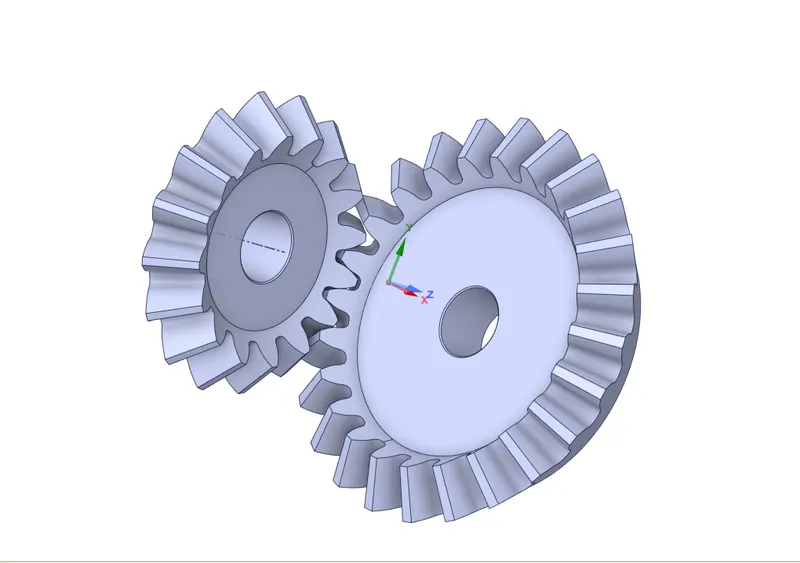
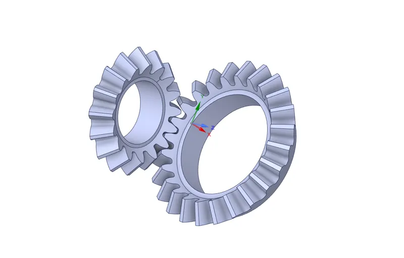
- The 3D modal(first figure) is imported into Ansys workbench for static structural analysis.
- The first figure is the actual geometry given.As the stress strain values are required at tooth contacts only,therefore the inner face of both the gears has been removed.
- Hence, analysis is carried out with the 2nd figure shown.
2.Material assignment
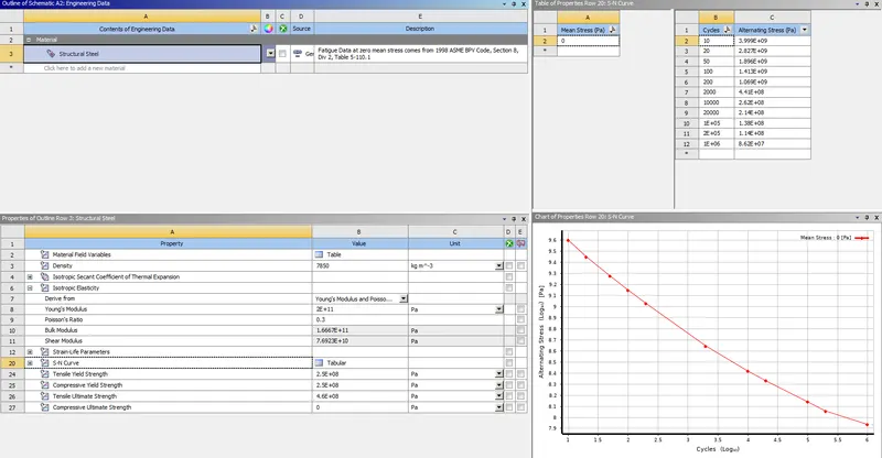
- Material used for bevel gears is structural steel.
- The details are shown below:
3.Contact details:
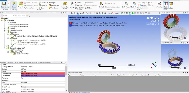
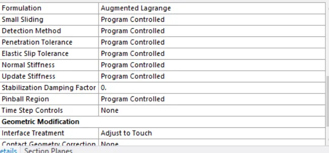
- Select all the tooth surfaces that are in contact for both gears.
- Type as frictional,formulation as Augumented lagrange contact penetration should be more controlled.Interface treatment as adjust to touch to avoid initial gaps and penetrations.
4.Joint details:
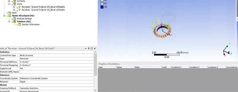
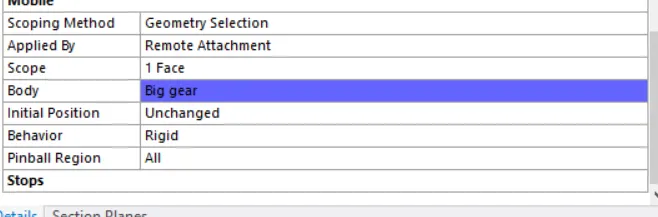
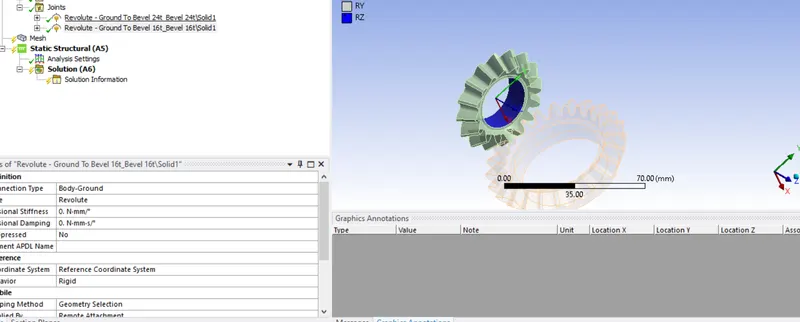
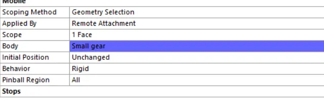
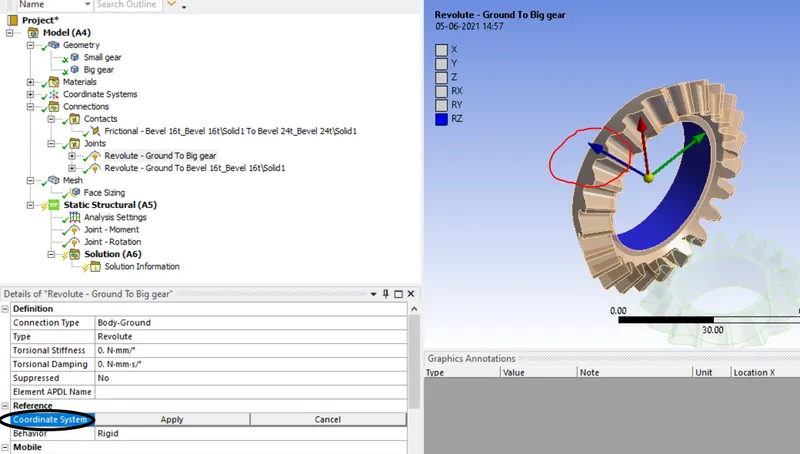
The bigger and smaller gears are assigned with revolute joints with body-ground contact.
5.Analysis settings:
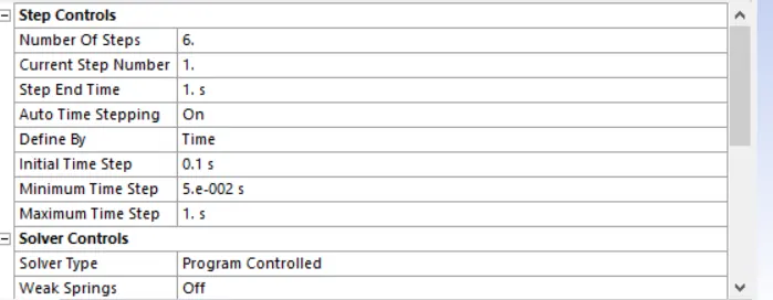
- Give the number of steps as 6.
- Auto time step on.
- Define by time.
- Large deflection on.
- Initial time step=0.2sec.Keep other values as it is.

6.Meshing
Bevel gears should be meshed with the different mesh sizes of 6mm,5mm and 4mm.Initially, default mesh has been generated.As a course mesh is formed at the tooth portions,refinement should be made to visualize structural behaviour at the tooth faces and improve accuracy of solution.Hence, face sizing is used with element size of 1.75mm.A finer mesh is obtained at the tooth faces.Also, the element/node limit is checked to overcome any type of errors.
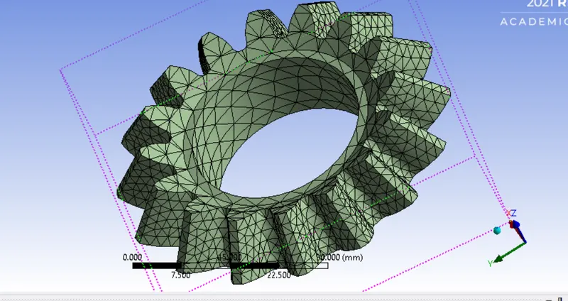
Small gear
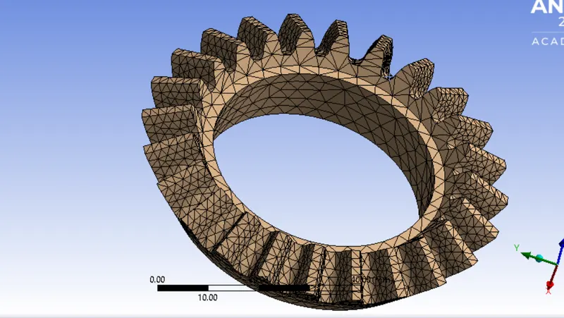
Big gear
Mesh size(mm) Number of nodes Number of elements
Case-1 6 25995 13940
Case-2 5 26782 14387
Case-3 4 27894 15002
Hence, the mesh sizes are under software mesh limits.
5.Boundary conditions:
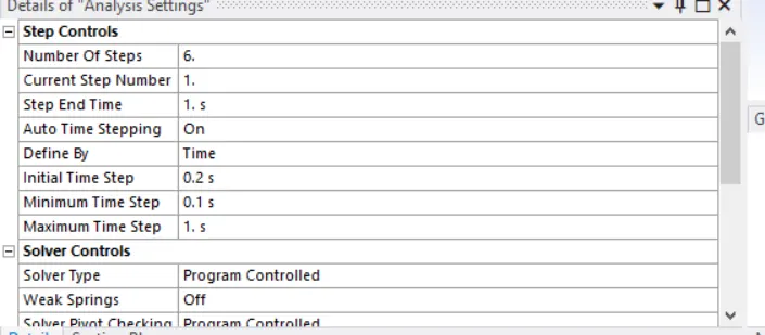
5.1 Analysis settings:
- Give the number of steps as 6.
- Auto time step on.
- Define by time.
- Large deflection on.
- Initial time step=0.1sec..Minimum time step=5e-2.Maximum time step=1sec.
5.2 Joint loads:
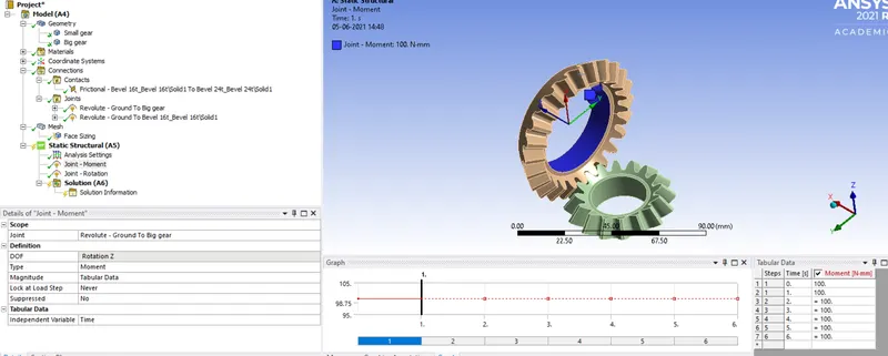
- Select joint load from static structural tool.
- For the bigger gear, insert the moment values of 100Nmm for all time steps.Also make sure to select the revolute joint created before.
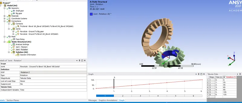
- Select the revolute joint for smaller gear. Give the rotation from 0 to 120 degrees in the table.
- The both gears have rotation in same sense. Go to revolute joint created for bigger gear and reverse the z-axis(axis of rotation).This will make the two gears to rotate in opposite directions as expected.
Solution:
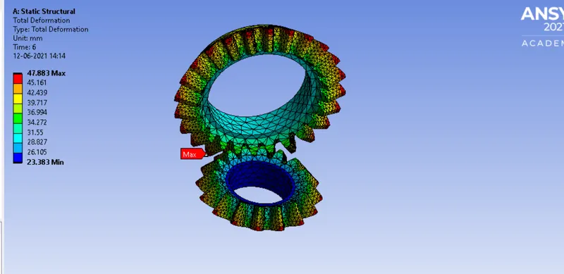
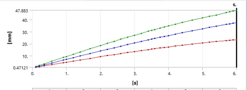
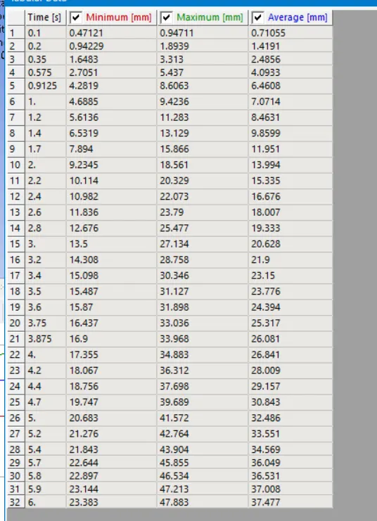
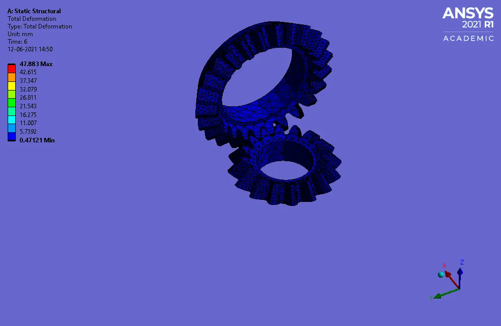
Total deformations:
Case-1:Mesh size of 6mm
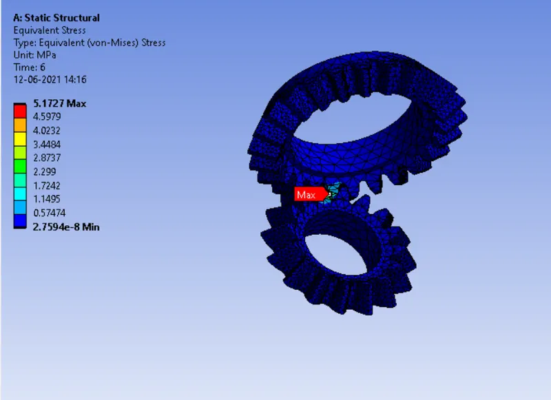
Case-2:Mesh size of 5mm
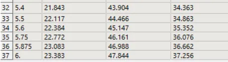
Case-3 Mesh size of 4mm
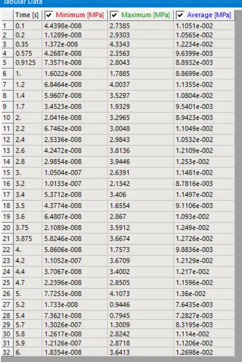
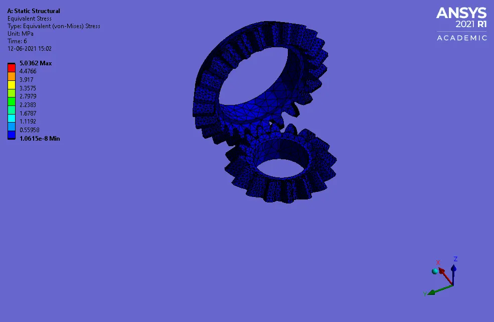
Equivalent stress:
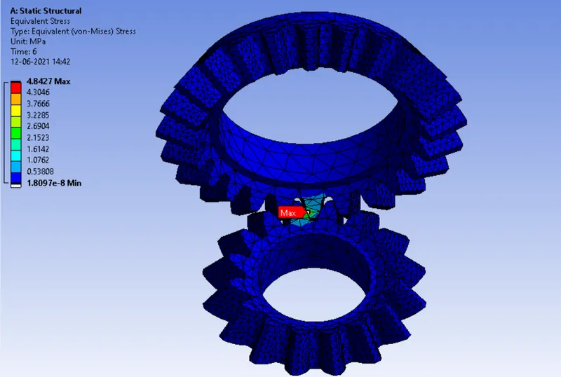
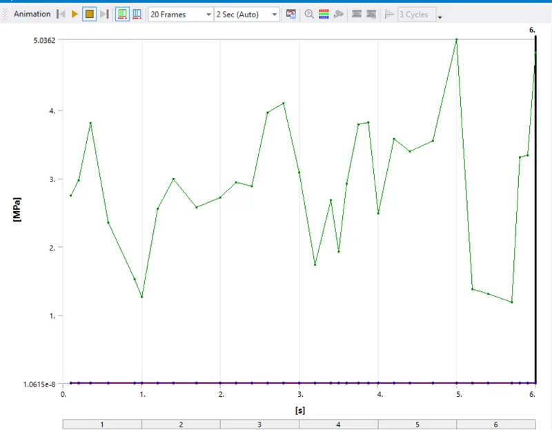
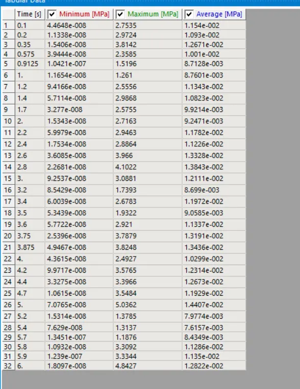
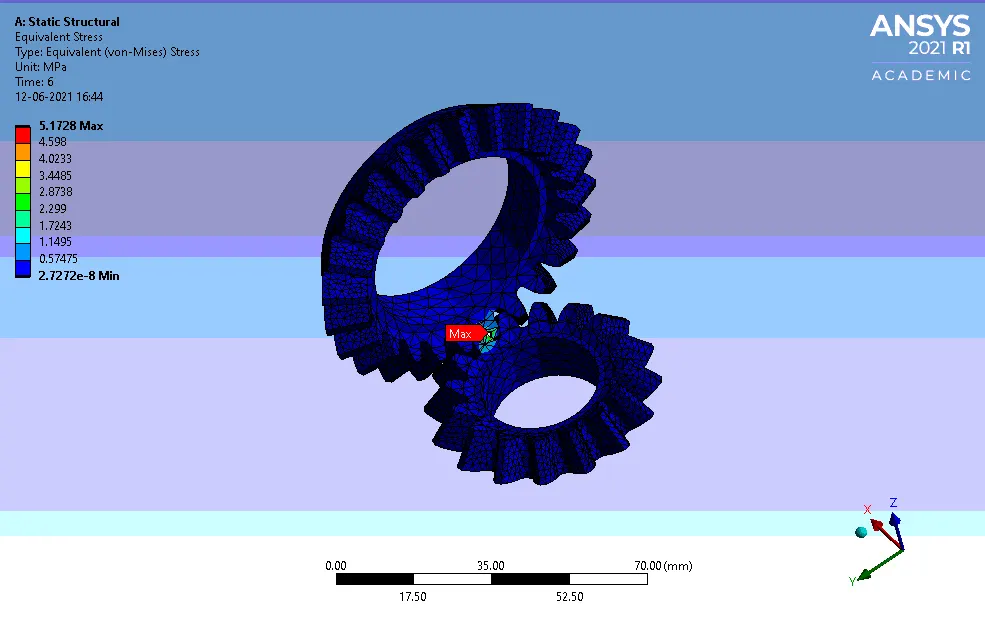
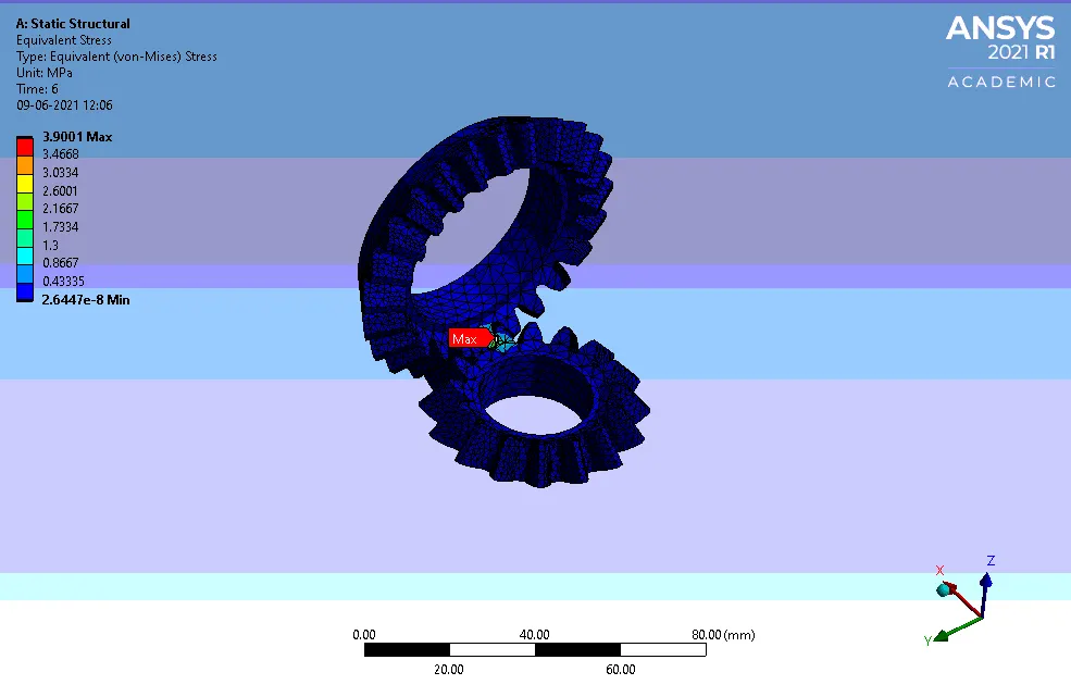
Case-1:Mesh size of 6mm
Case-2:Mesh size of 5mm
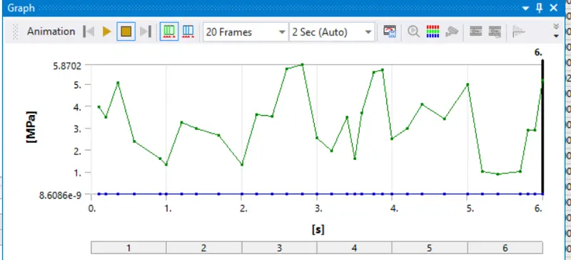
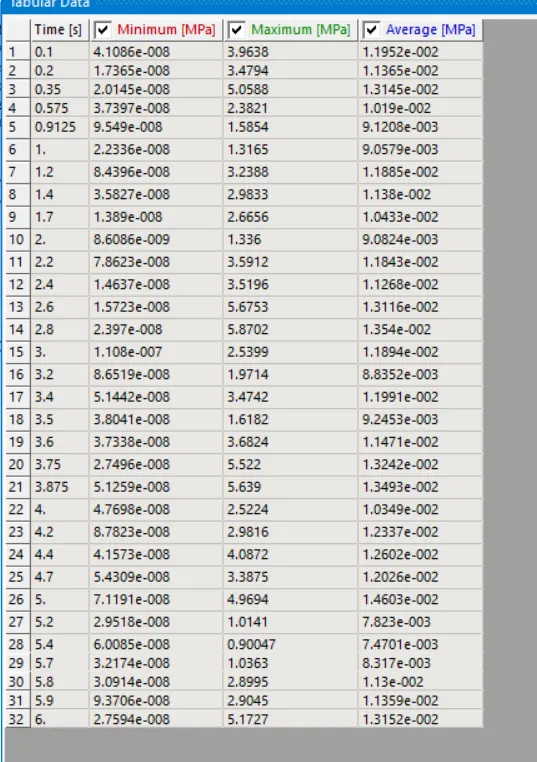
Case-3 Mesh size of 4mm
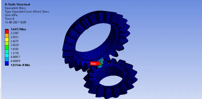
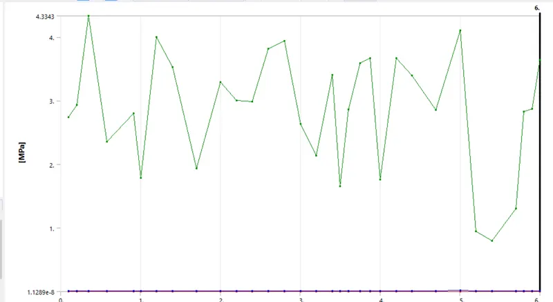
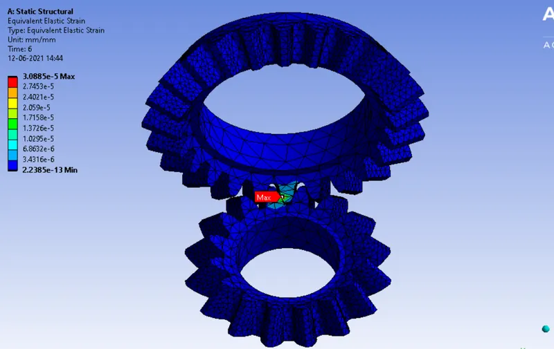
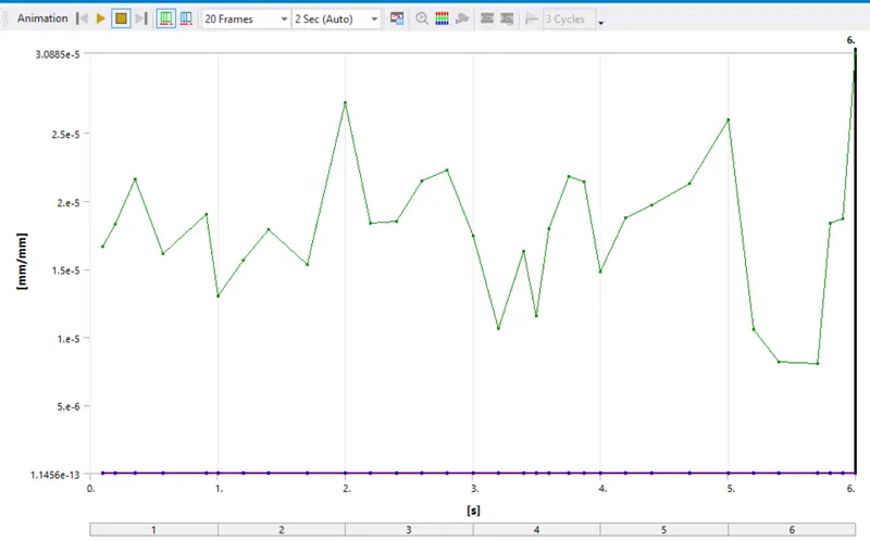
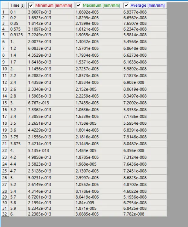
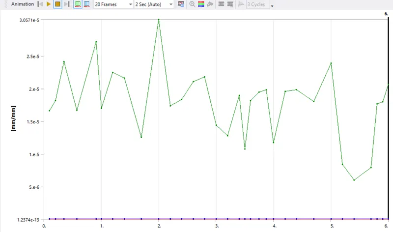
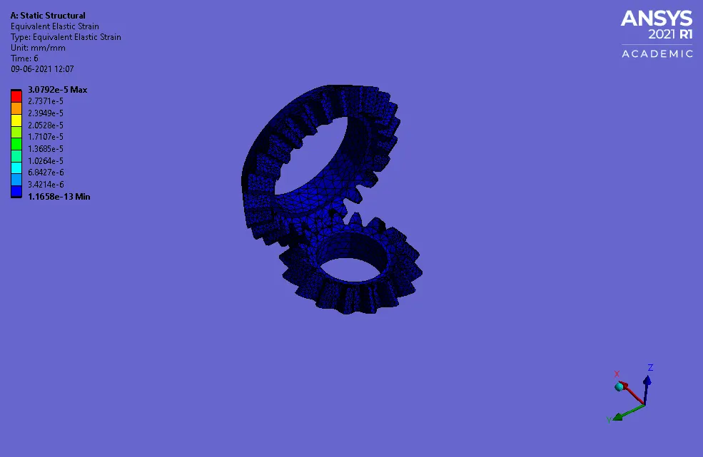
Equivalent elastic strain:
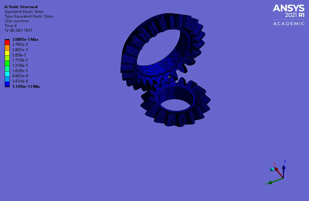
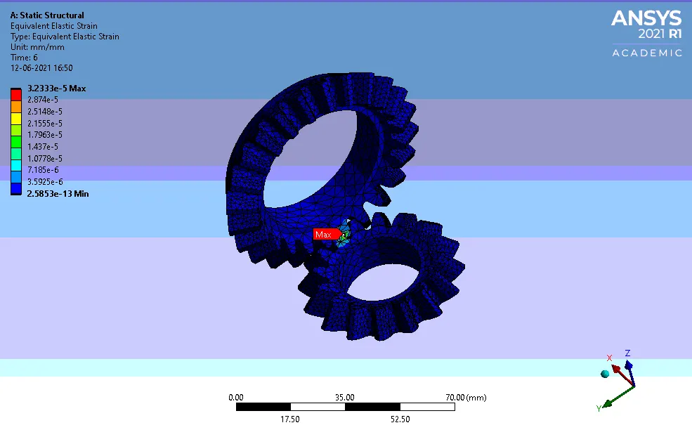
Case-1 Mesh size of 6mm:
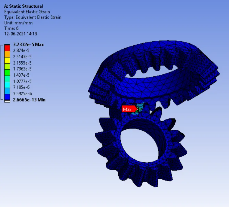
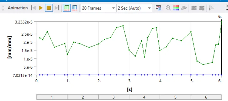
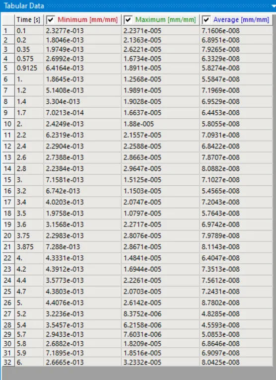
Case-2 Mesh size of 5mm
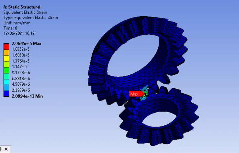
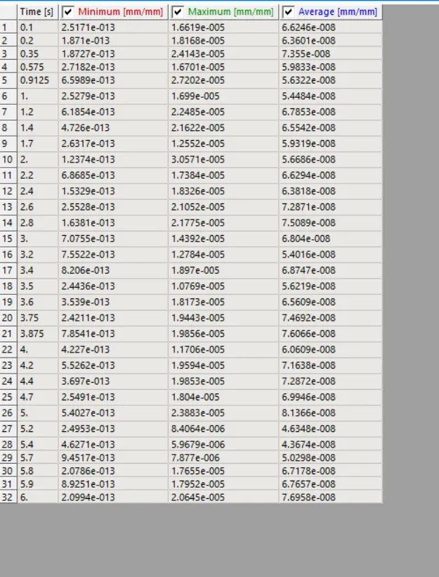
Case-3 Mesh size of 4mm
Comparsion of results:
The maximum and minimum values of total deformation, equivalent stress, equivalent elastic strain for the 3 cases are presented below:
Total deformation(mm) Equivalent stress(MPa) Equivalent elastic strain(mm/mm)
Min Max Min Max Min Max
Case-1 23.383 47.883 1.8097e-008 4.8427 2.2385e-013 3.0885e-005
Case-2 23.383 47.883 2.7594e-008 5.1727 2.6665e-013 3.2332e-005
Case-3 23.383 47.883 1.8354e-008 3.6413 2.0994e-013 2.0645e-0055
It can be seen that deformation values for all cases are same.The maximum equivalent elastic strain values for case-1 and case-2 are nearly same.Although the equivalent stress is minimum for case-3, but its has very little change in values of stresses for the 3 cases especially for case 1 and case-2.Hence, the results turn out to be independent of mesh grids for case-1and case-2.
Animations:
Total deformations:
Case-1 Mesh size of 6mm
Case-2 Mesh size of 5mm
Case-3 Mesh size of 4mm
Equivalent stress:
Case-1 Mesh size of 6mm
Case-2 Mesh size of 5mm
Case-3 Mesh size of 4mm
Equivalent elastic strain:
Case-1 Mesh size of 6mm
Case-2 Mesh size of 5mm
Case-3 Mesh size of 4mm
Conclusion:
- From grid dependency test, it can be concluded that results for case-1and case-2 are independent of mesh.
- Also, further mesh refinement would not change the results significantly.