Week 1 Stress Concentration on a Plate with hole
Aim: To simulate the 2 modals given and compare their deformation and stress developed and check which design suits best for analysis and manufacturing standpoint.
Procedure:
CASE-1
1. Open the ansys workbench.
2. Select Static Structural analysis system.Rename it to Plate with hole case 1.
3.Right click on geometry tool and select 'Edit geometry in Spaceclaim'.
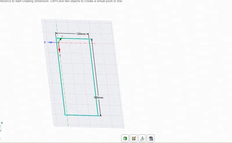
4. Now,the spaceclaim GUI appears. Select a rectangle and create it in the sketch plane with dimensions given.
Plate dimensions:
Length=300mm
Height=120mm
Thickness=30mm
Circular Hole at the center:
Diameter=60mm
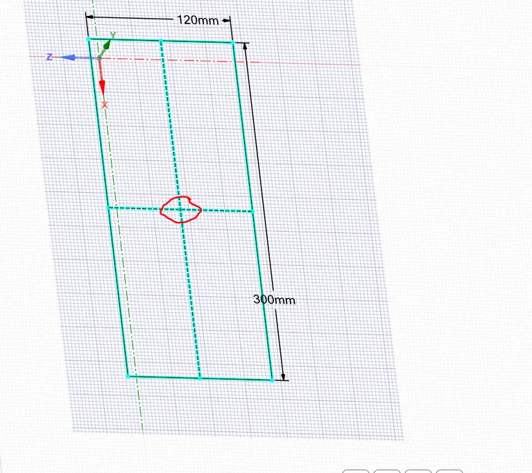
5.Select the construction lines and make 2 construction lines from mid points of the rectangle lines as shown in fig and we got the centre of geometry.
6. Create a circle at the centre with diamter 60mm.
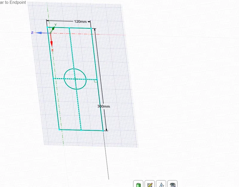
7.Now delete the construction lines and select 3d mode to create a surface.
8. Now delete the hole so that object will be hollow.
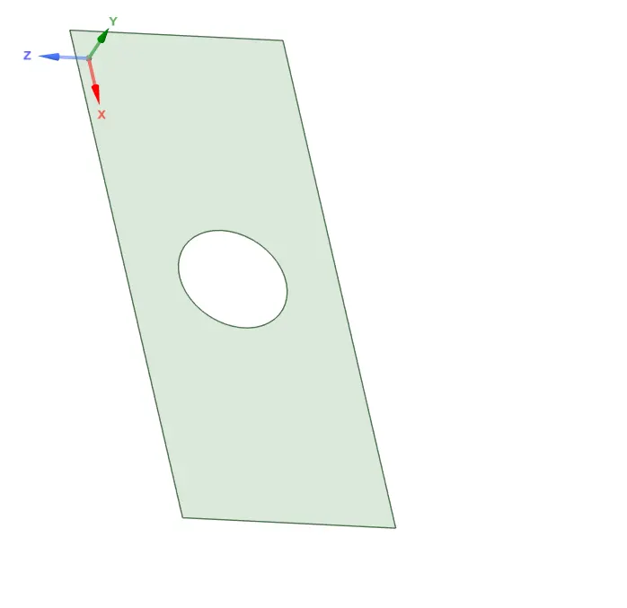
9. Select pull option and pull the component with thickness 30mm.Hence, geometry is completed.
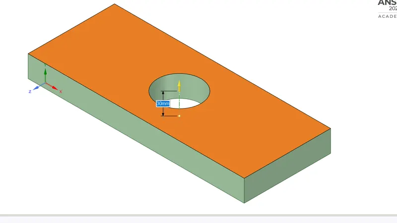
10. Close spaceclaim. Go to Mesh.
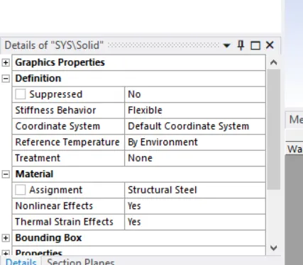
11.Select geometry and assign the material Structural Steel to the component from the details menu as shown.Also make sure that the modal is in true scale.
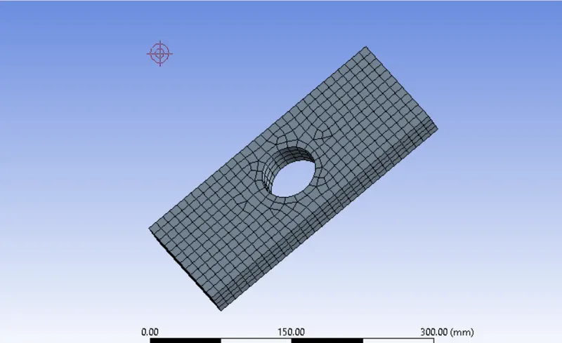
12.Perform the default meshing. As seen from fig this is a course mesh, also elements are 2D but we need 3D ones.
13.Change element size to 2mm.Make sure to check the number of nodes and elements that is software size limits by going to statistics under mesh tool.In this case 128K is maximum size limit of nodes/elements.
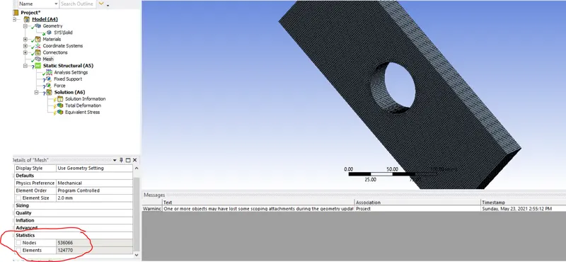
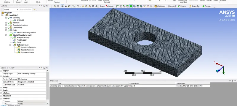
14.This element size exceeds the size limit of software,Hence change again the size and do the iterations until it becomes less than the maximum limit.Hence we set the element size as 4mm as an optimized value.
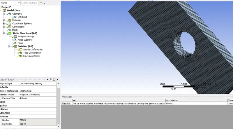
15. Choose the method option under mesh tool.Select the tetrahedron elements for meshing.And hence update the mesh.
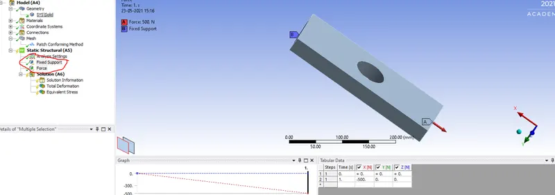
16.Go to Static structural and choose the left face as an fixed support and give a force value of 500N in -x-axis for the right face.
17.Now go to solution and solve the mathematical modal.
18. Right click on solution and select insert and choose the total deformation and equivalent stress and click solve.
Results:
Below are the final contours obtained:
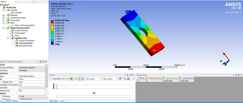
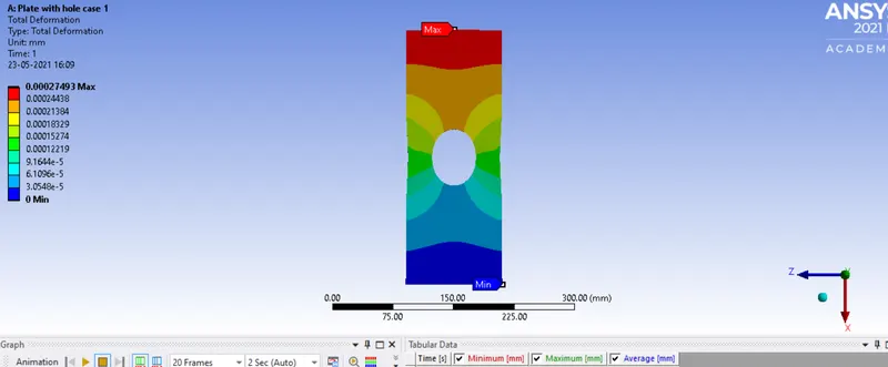
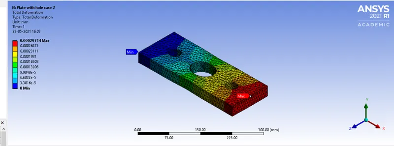
Maximum and Minimum Deformation:
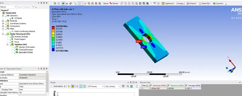
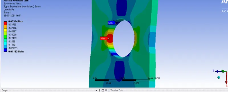
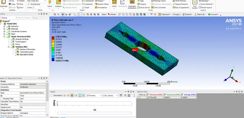
Maximum and Minimum Equivalent stress:
20. Save the file.
CASE -2
1.Go to workbench of same file saved.Select static structural analysis system again. Rename it to Plate with hole case-2.
2.Open spaceclaim under geometry and make the modal with given dimensions below.
smaller holes 90mm away from the center:
Diameter=30mm
Boundary Conditions:
Plate fixed at left face.
Load of 500N on the right face.
3. To make the geometry, similar procedure is followed as in case-1 with the difference in 2 more hole creation.
4.For that select construction line and choose the centre of rectangle as 1st point and second point at a distance of 90mm as shown and create the circles in both directions of specified diameters.
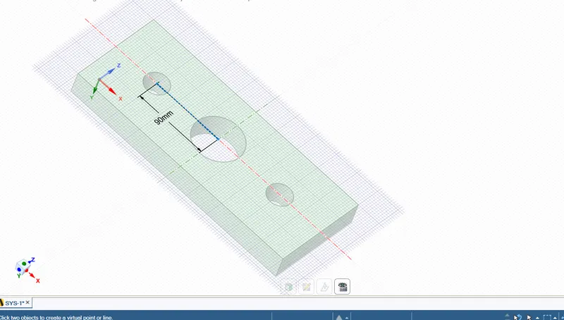
5.Delete all the construction lines and the 2D circles to make a hollow object.
6. Pull the component with same thickness and hence the geometry is obtained.
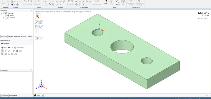
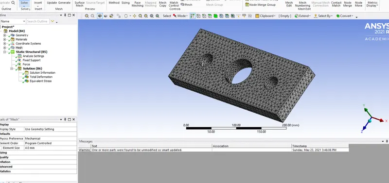
7. Go to meshing. Assign the material, make element size 4mm and insert a tetrahedron method as in the case-1.The meshed modal is shown below.
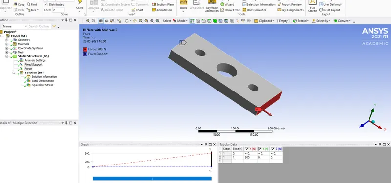
8. Assign the boundary conditions of mathematical modal under static structural. Here the left face is kept as a fixed support and a force of 500N is applied to the right face as shown.
9.Solve the problem under Solution and obtain the stress and deformation results.
Results:
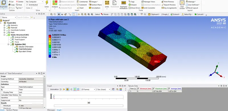
Maximum and minimum deformation:
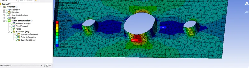
Maximum and Minimum equivalent stress:
Comparison between Case-1 and Case-2:
Max Deformation(mm) Maximum stress(MPa)
Case-1 0.00027493 0.60304
Case-2 0.00029714 0.58374
From the above results obtained, it can be concluded that Case-2 has least maximum stress generated as compared to Case-1.Location of maximum stress for both the cases is on the large cut hole as it has higher stress concentration region than all the other portions of the geometry.The maximum deformation is higher for Case-2 as compared to Case-1 and its location is at the place of application of force.
From analysis standpoint, it can be seen from results that Case-2 has least stress generated, therefore it is more safe and reliable as compared to Case-1 scenerio.Hence we choose the design corresponding to Case-2.
From manufacturing standpoint, production time and material wastage are the 2 aspects which should be minimized.As Case-2 demands more time and material wastage(holes),hence we go for Case-1 which is relatively simpler to manufacture with minimum time and material consumed.