Week 2 Bevel Gear Challenge
- Grid Dependency Test: Whenever we are going to find a numerical solution through discretization, there will be no. of grid points that will be created. It is well known that higher the no. of grid points, the
more accurate the solution will be. But once the solution starts converging, increasing the no. of grid points will no longer yeild noticeable changes in the values of calculated variables. In addition, it will also
add to the increase in CPU resource cost and time required to complete the simulation. So it becomes nescessary to calculate the optimum number of grid points that is used to run the simulation. The test
used for finding this optimum number of grid points that is used to run the simulation is known as Grid Dependcency Test. This is done by refining the mesh size until the solution can no longer yeild
appreciable noticeable difference in the values of calculated variable.
- Objective: To perform a grid dependency test for the Bevel gear simulation for mesh sizes of 6,5 and 4 mm and compare the results.
- Procedure: Open the static structural analysis system in the Project schematic. The material that is used to perform the analysis is structural Steel which is available by default in the material library, so
there is no need to update the Engineering Data. Import the given model and open Spaceclaim. As seen below, we can do small geometry cleanup in the model. Delete the inner solid portion of both the
gears, since we are only interested in the stresses that will be generated in the portion of gear tooths when they rotate.
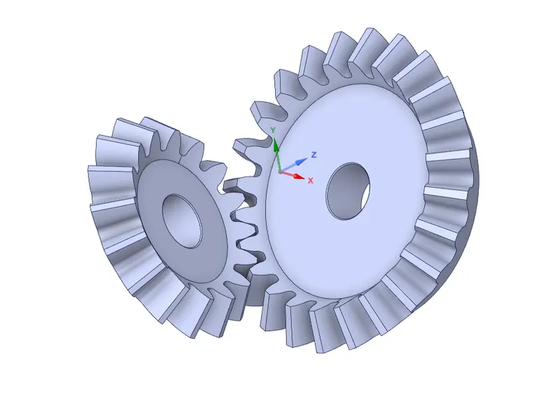
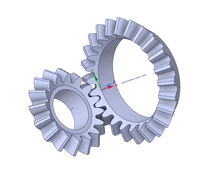
Select the surface of the part that is to be deleted and draw a circle on it with the same centre as that of the selected circlular surface. Use diamter of 45 mm and 25 mm respectively on the bigger gear and
smaller gear. Using Pull option drag the circles and remove the unwanted part of the gear.
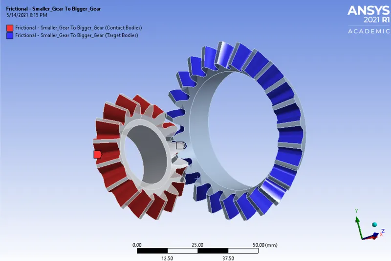
Now update the model and open Mechanical modeler. Whenever there is contact between any geometries, Ansys Contact Detection detects it and defines contact between them. Since all the gear tooths of
both gear will be in contact with each other, update all the Target and Contact faces in the Contact definition that will come in contact with each other throughout the simulation.
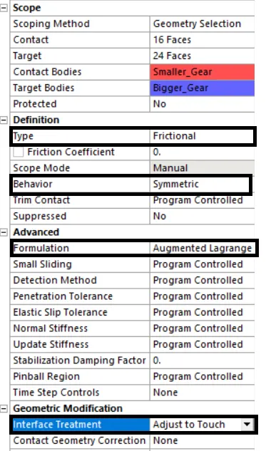
Following properties are used in the contact definition:
Now we need to define revolute joint to rotate the gear about an axis. Right Click on Contacts > Insert > Joints. Select the connection type as Body – Ground. In the Scope selector, select the inner surface
of the gear as shown below. Similarly, define revolute joint for the other gear.
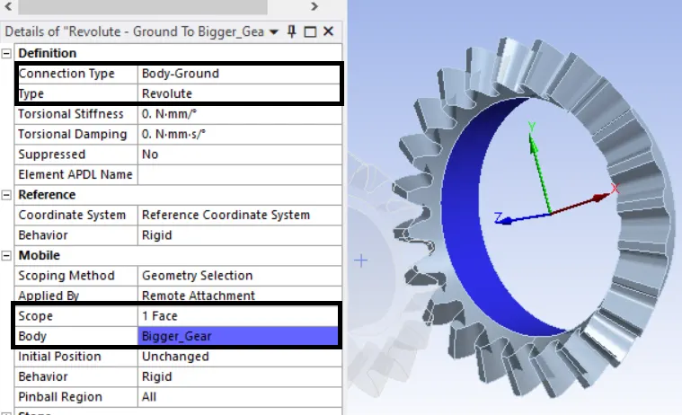
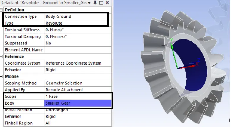
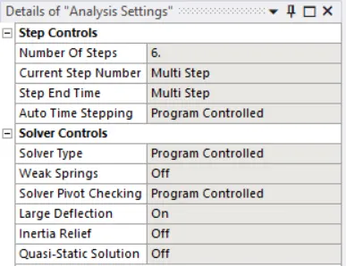
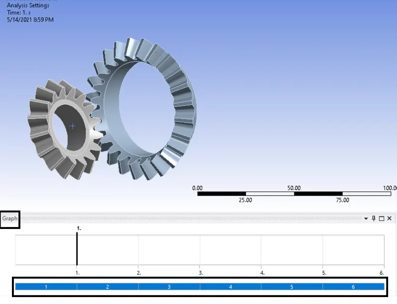
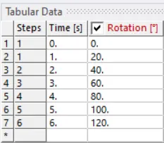
Now rotate the gear by 120 degree. Instead of giving this rotation in one single step, we will divide it in six steps. Click on Analysis settings and enter No. of steps = 6. Instead of setting each individual
step, select all the steps under the Graph option and set the following parameters.
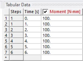
Now we can insert the joint load. To insert joint load, click on Static structural > Insert > Joint load. Under joint selector, select Revolute - Ground to Bigger_gear joint with type as Momemt. For Magnitude,
give input in tabular form as shown below.
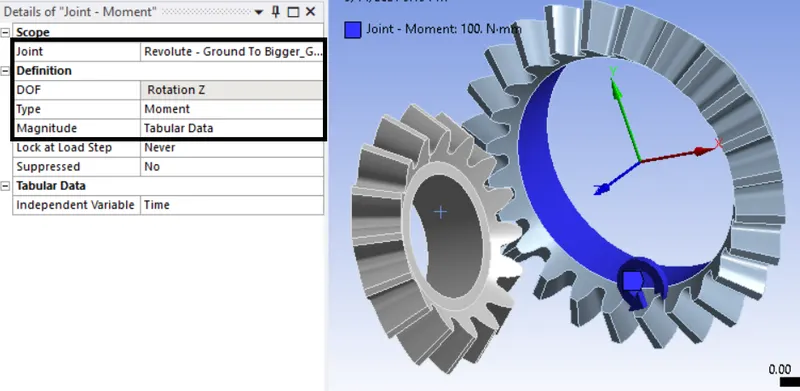
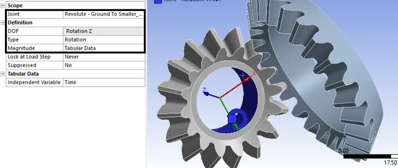
Now similarly specify the joint load on the Smaller_Gear. Insert another joint and in the joint selector, select the Revolute - Ground to Smaller_Gear joint with type as rotation with following magnitude:
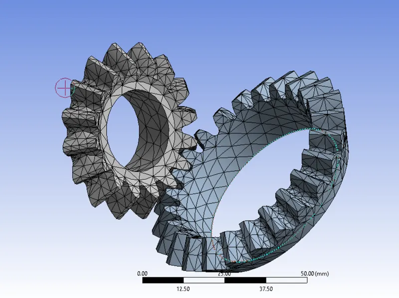
The component is first meshed with an element size of 6mm. As seen below, the mesh is very course. It is okay for the uniform portion of the gear, but in the gear tooth portion, which is critical portion
and the area of our interest, the mesh size will create convergence issue. To prevent this, use face sizing in the gear tooth portion of both the gear.
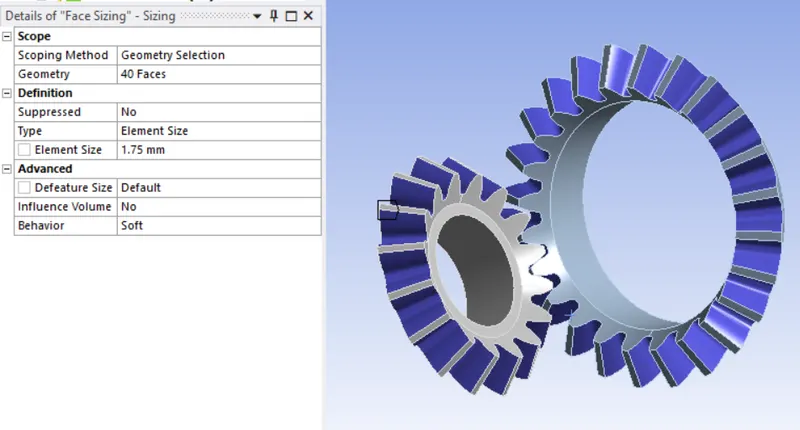
Go to Mesh > Insert > Sizing. Select all the tooth faces that will be in contact during the simulation. Give element size of 1.75 mm and generate the mesh. The mesh looks better now in the gear tooth
portion.
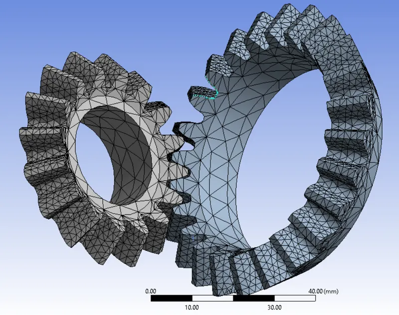
Run the simulation and view the results.
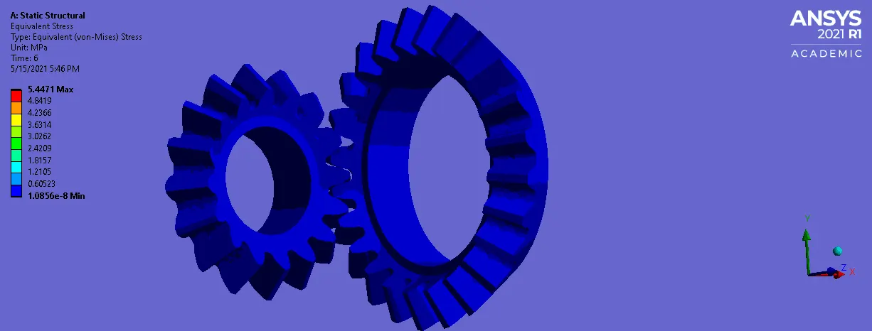
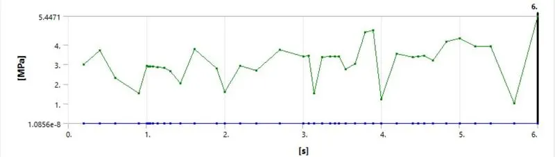
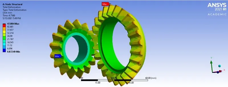
- Case 1: General mesh size 6 mm and face sizing of 1.75 mm at the gear tooth portion.
Stress Contour:
Deformation:
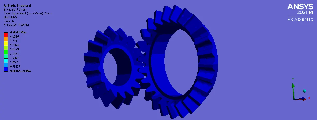
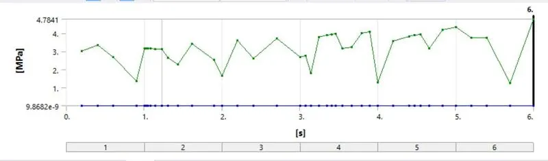
- Case 2: General mesh size 5 mm and face sizing of 1.75 mm at the gear tooth portion.
Stress Contour:
Deformation:
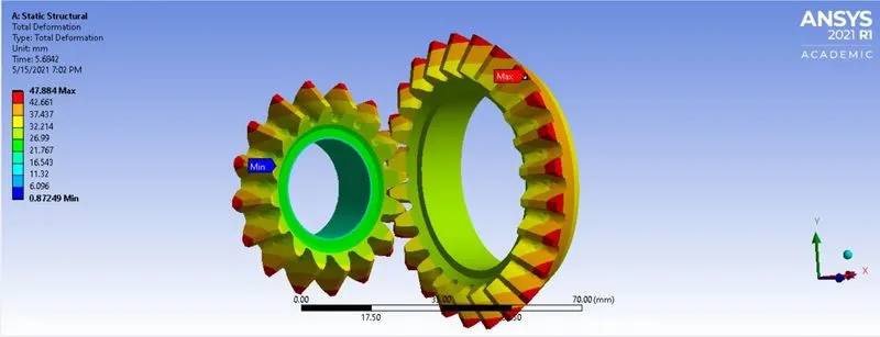
- Case 3: General mesh size 4 mm and face sizing of 1.75 mm at the gear tooth portion.
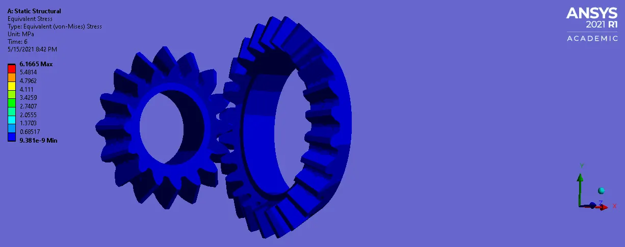
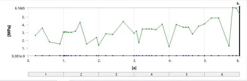
Stress Contour:
Deformation:
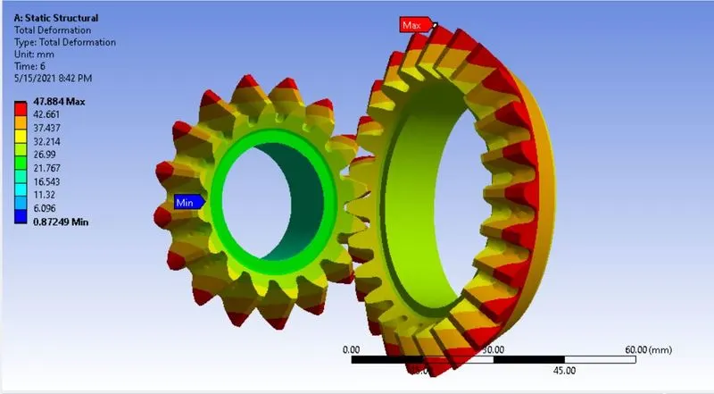

It is observed that for the given mesh sizes, the mesh size with 4 mm gives highest amount of stress induced in the given gear model. This is because the lower size of mesh gives more no. of grid points
and better interpolation of nodal results on the elements. Thus for the given mesh sizes, the mesh size of 4 mm is preferred.
- Conclusion: Thus the grid dependency test for the Bevel gear simulation for mesh sizes of 6, 5 and 4 mm is completed.