Week 2 Bevel Gear Challenge
Aim: To perform a grid dependency test on a bevel gear and to observe total deformation, elastic strain, and equivalent stress
Principle:
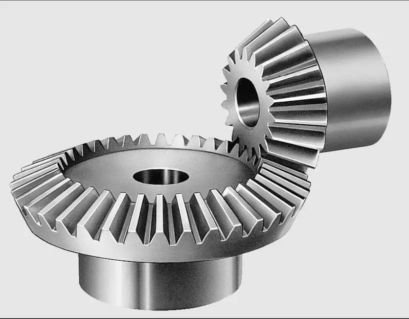
Bevel gears are gears where the axes of the two shafts intersect and the tooth-bearing faces of the gears themselves are conically shaped. Bevel gears are most often mounted on shafts that are 90 degrees apart, but can be designed to work at other angles as well. The pitch surface of bevel gears is a cone, known as a pitch cone. Bevel gears transfer energy from linear to vertical power, making them very useful in machines widely used in mechanical settings.
Procedure:
The analysis we are doing is a static structural analysis and structural steel is selected as the material
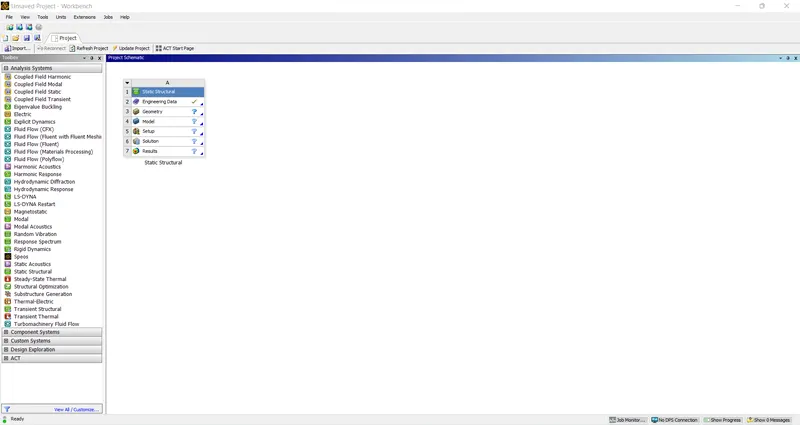
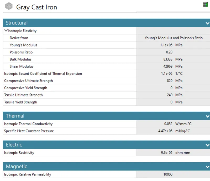
Before we can begin analysis we need to create a model with the given dimensions but since the model is already given it is imported using the import option in the geometry
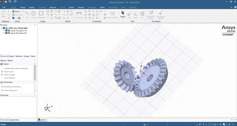
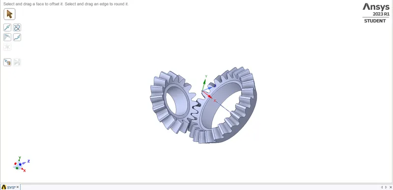
Since our primary goal is to conduct analysis only on the teeth of the gears and the middle part is not much of importance it is removed as it takes less time for computation
Once the 3D model is uploaded meshing has to be done,
We have to perform mesh of different sizes over materials 4, 5, and 6 respectively. There is a program-controlled mesh of 1.75 mm for the face sizing so that the mesh could get finer than coarse. Lastly, we are generating a fine mesh over the bevel gear which is further carried out to give the desired result:
Case 1: Mesh size_6mm
Case 2: Mesh size_5mm
Case 3: Mesh size_4mm
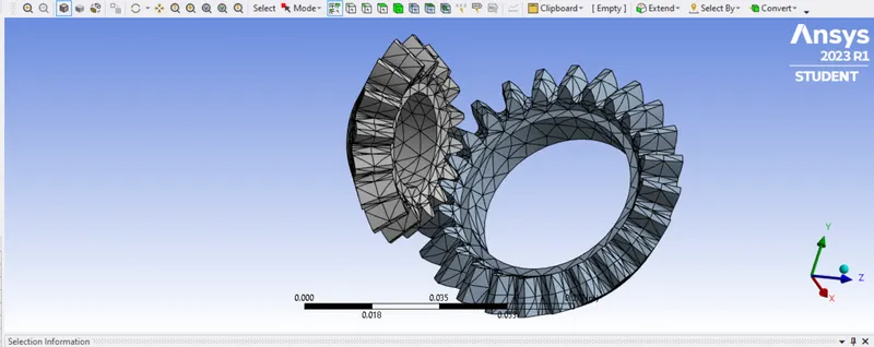
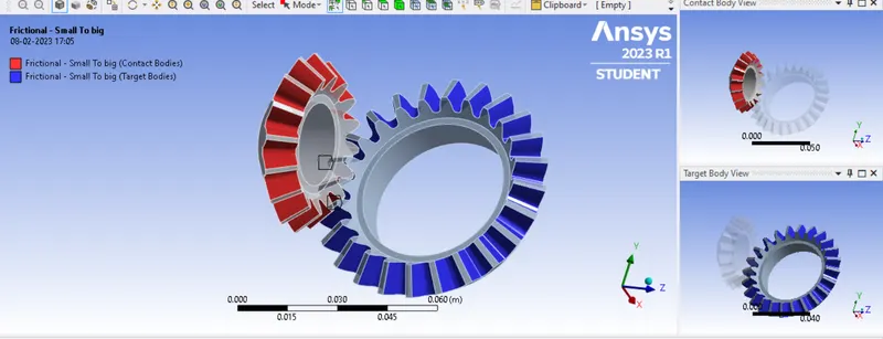
Since two gears always are in contact all the surfaces are selected in the contact options
A joint is defined as gears to rotate about an axis. A revolute type of joint was defined for both parts. This can be done using right-click contact>insert>joint. Connection type was defined as body-ground (Specifying the frame of reference), and type as revolute. Now select the inner surface to define the scope as shown below.
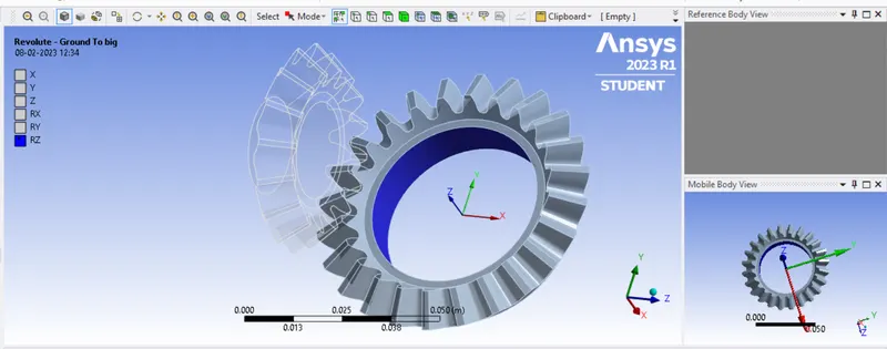
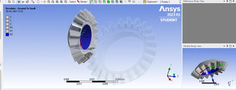
For Analysis In static structural assign the joints to the left gear and right gear as rotation and a moment.
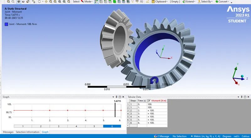
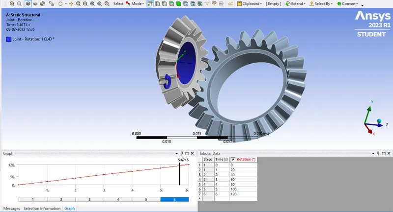
The big gear is assigned as rotation and the left gear is assigned as a moment.
Grid dependency test:
A grid dependency test is a statistical method used to check whether the results obtained from a simulation model are dependent on the spatial resolution of the grid used to discretize the simulation domain. The purpose of this test is to ensure that the results of the simulation are not influenced by the grid resolution and that they have converged to a stable solution that is independent of the grid size. The use of grid dependency tests is common in many scientific and engineering applications, such as numerical weather forecasting, computational fluid dynamics, and geophysics, among others. These tests are an important step in the verification and validation of numerical models, as they help to ensure that the results obtained from these models are robust and accurate.
Results:
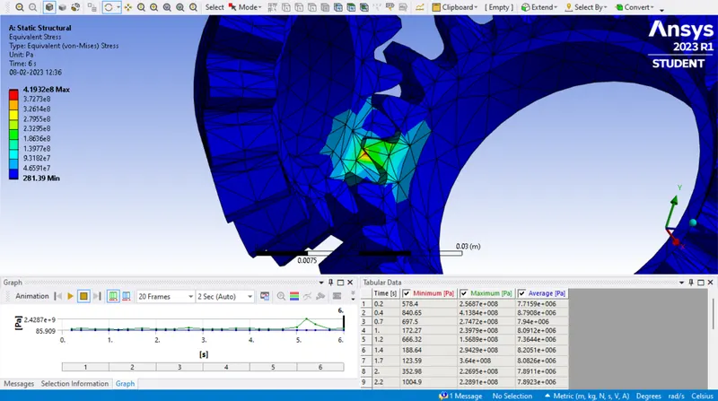
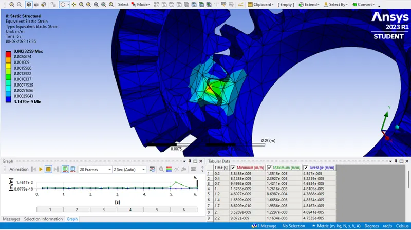
Mesh size6:
1:Total deformation
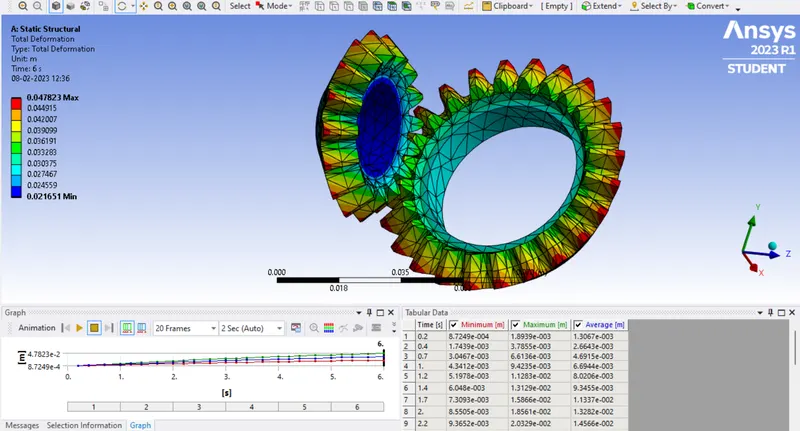
2:Stress
3:Strain
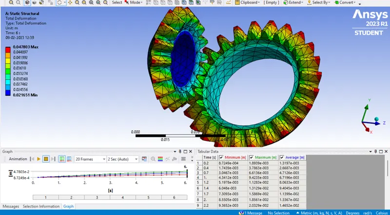
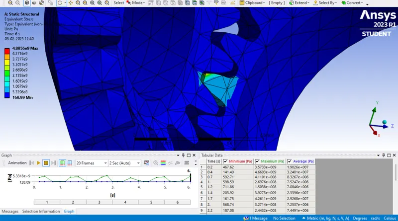
For mesh Size5:
1: Total deformation
2:Stress
3:Strain
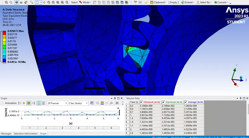
For mesh size 4
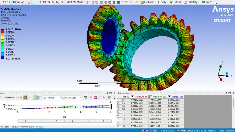
1:Total deformation
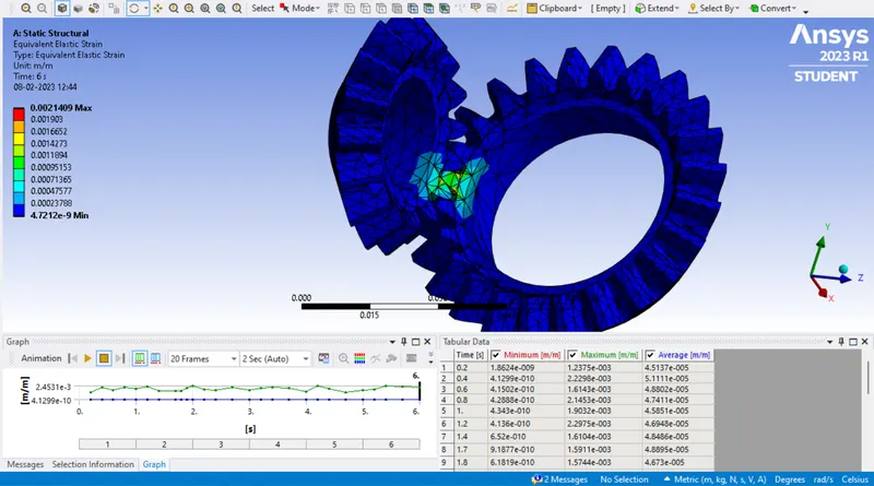
2:Strain
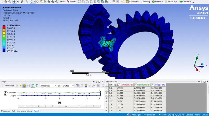
3:Stress
Comparing the results:
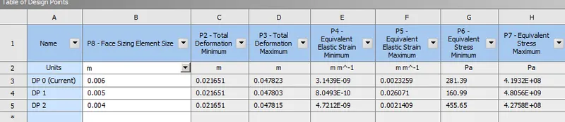
on comparing the results of the bevel gear of different mesh sizes we can observe that
- total deformation is similar in all three cases.
- The values of equivalent elastic strain is decreasing when we decrease the mesh size, there is a small change in values of strain.
- Likewise, strain, and equivalent stress value also changes with the mesh size.