Week 2 Bevel Gear Challenge
STRUCTURAL ANALYSIS OF BEVEL GEAR
OBJECTIVE :- Following are the objective of the given challenge
(a) Explain the terminology of grid dependency test
(b) Perform the Simulation on the given st of bevel gear
(c) Perfrom meshing on the CAD model of bevel gear and perform grid dependency test on the CAD with Mesh size as 4mm, 5mm, 6mm
THEORY :-
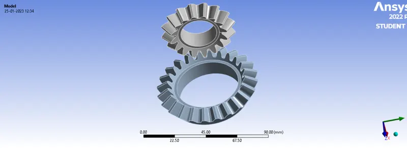
Bevel Gear :- These are the type of gears which transfer the motion shafts which are perpendicular to each other.
Grid Dependency Test :- This is a test done in CAE Analysis to investigate the dependency of grid size by using refined mesh. Finer the mesh size higher would be the accuracy of the solution. Also, by decreasing the size of the mesh, the computational time and cost increases. therefore this test is to perform to estimate the optimum size of the mesh as per the requirement of the industry.
CAD IMAGE :-
PROCEDURE :-
1. The structural steel module was selected in the ansys.
2. CAD model was imported and it was editted in the SPACE CLAIM module.
3. Material of the bevel Gear was selected as structural steel
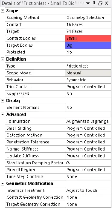
4. Contact and Target faces were selected as per the requirement in the CAD. In connection type was defined as Friction less. Behaviour was selected as symmetric, formulation was selected as augmented lagrangean and finally interface treat ment was given as adjust to touch. following is the screen shot :-
5. Post this the joint was defined for Big and Small Gear.
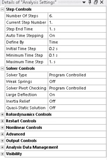
6. Next is to give the analysis setting for the simulation , following is the screen shot of the same
7. Next step was to assign the the mesh size to the CAD geometry
8. For the sollution Von-Mises stress, Equivalent elastic strain, and Total Deformation was selected for observation .
Case Wise Study
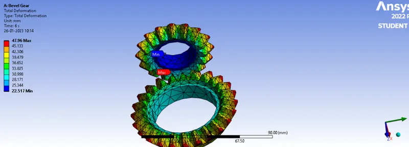
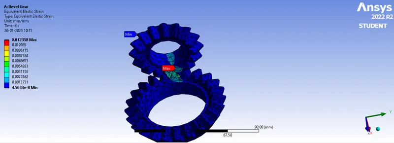
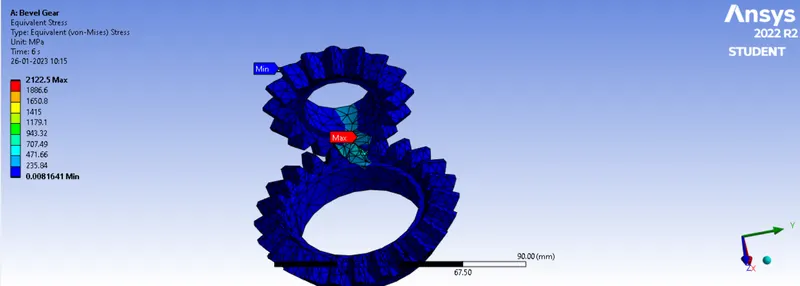
CASE -1 - 6mm
Total Deformation
Equivalent Strain
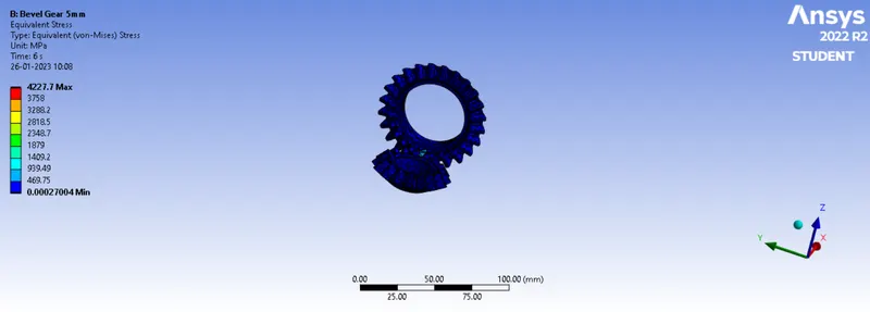
Equivalent Stress
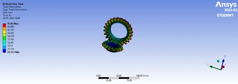
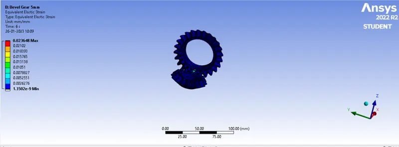
CASE -2 - 5mm
Total Deformation
Equivalent Strain
Equivalent Stress
CASE -3 - 4mm
Total Deformation
Equivalent Strain
Equivalent Stress
RESULTS :-
The Results of the simulation under taken are as follows :-

Ellapsed Time for simulation
Case -1- 6mm- 64 Sec
Case -1- 5mm- 155 Sec
Case -1- 4mm- 364 Sec
CONCLUSION :-
1. From the results it is concluded that as the mesh size is decreased, the solution tend towards more accurate value. but for considering the total deforamtion value it can be observed that the results were more or less the same. therfore for calculation of deformation coarser mesh for this case can be used.
2. It can be seen that decreasing the size of grids computational time increases.