Week 3 Sheet metal Bending challenge
SHEET METAL BENDING CHALLENGE
Objective: - To Simulate sheet metal bending challenge with three different materials (Aluminium Alloy 1199, Copper Alloy NL & Magnesium Alloy NL) and find out Equivalent Stress, Equivalent Elastic Strain & Total Deformation in the Y direction and compare the results for the three materials.
CAD Model of the Punch, Sheet and Die is incorporated for Analysis (Front view & Isometric view)
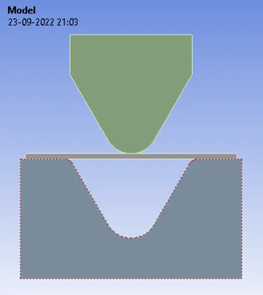
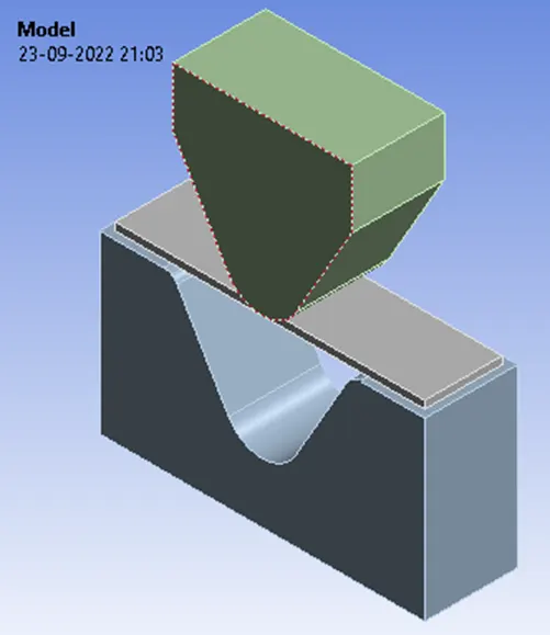
Material Properties took from Engineering Data Sources of Ansys Workbench.
|
Material Specifications for |
Density (Kgm^-3) |
Young’s Modulus [MPa] |
Bulk Modulus [MPa] |
Shear Modulus [MPa] |
Yield Strength [MPa] |
Tangent Modulus [MPa] |
|
Case I Aluminium Alloy 1199 |
2770 |
62000 or 6.2e10 pa |
60784 or 6.0784e10 pa |
23308 or 2.3308e10 pa |
140 or 1.4e8 pa |
209.46 or 2.0946e8 pa |
|
Case II Copper Alloy NL |
8300 |
110000 or 1.1e11 pa |
114580 or 1.1458e11 pa |
41045 or 4.1045e10 pa |
280 or 2.8e8 pa |
1150 or 1.15e9 pa |
|
Case III Magnesium Alloy NL |
1800 |
45000 or 4.5e10 pa |
50000 or 5e10 pa |
16667 or 1.6667e10 pa |
193 or 1.93e8 pa |
920 or 9.2e8 pa |
Young’s Modulus
Young's modulus or modulus of elasticity is the mechanical property that measures the tensile or compressive stiffness of a solid when the force is applied lengthwise or along its length.
What is the principle of Young's modulus?
The basic principle is that a material undergoes elastic deformation when it is compressed or extended, returning to its original shape when the load is removed. More deformation occurs in a flexible material compared to that of a stiff material. In other words: A low Young's modulus value means a solid is elastic or flexible and a High Young's modulus value means a solid is a stiff Firm or inflexible.
Rigidity: It is the ability of a material to not bend when a force is applied.
What is Stiffness?
Stiffness is the extent to which how a component or object resists/opposes/act against an elastic deformation when a load is applied.
How Is Stiffness Calculated?
Now, we can redefine stiffness as the ability of a material to distribute a load and resist deformation. From this, we can get understand that stiffness depends on Forces and Deformations. Mathematically, we can say that Stiffness is force per unit deformation. It is denoted as K.
What Is Flexibility?
Flexibility is rather very easy and self-explanatory. It can be defined as the inverse of Stiffness. Instead of resisting the force, the body tends to move/bend along the force.
In other words, if a body is stiff then the deformations are small. If a body is less stiff (flexible) then deformations are huge.
You might think, you want a stiffer member in all the cases. You would rather not. Stiffer members fail suddenly, more like a brittle failure with no prior warnings.
What Is Strength?
We can define this more easily with a stress-strain curve. Maximum stress taken by a material is called Strength. In other words, the maximum load taken by the material before its failure is called Strength.
Strength is classified into many types based on its failure.
Yield Strength The load after which the plastic behaviour or permanent deformation starts in a material. In other words, the load above which the material cannot regain its original shape is called Yield Strength. When a material yields, the stiffness of that material is reduced. Yield Strength - The amount of force a material can withstand when pulled from opposing sides without suffering permanent deformation.
Ultimate Strength Maximum/peak load that a material can take. This is higher than Yield Strength in many cases. For brittle materials, this value is close to that of yield strength. or The amount of force a material can withstand when pulled from opposing sides without completely breaking. Also known as ultimate tensile strength.
What is bulk modulus vs Young's modulus?
Young's Modulus is the ability of any material to resist the change along its length.
Bulk Modulus is the ability of any material to resist the change in its volume.
The bulk modulus is a constant that describes how resistant a substance is to compression Bulk Modulus is the measure of the ability of a substance to withstand changes in volume when it undergoes compression on all sides.
It is defined as the ratio between pressure increase and the resulting decrease in a material's volume.
The bulk modulus is basically used to measure the incompressibility of a material. Incompressible or non-compressible fluids and solids will not change in volume if pressure is applied.
Why bulk modulus is always positive?
Whenever you compress something its pressure increases and so bulk modulus is positive
What is shear modulus?
Shear modulus, also known as the Modulus of rigidity, is the measure of the rigidity of the body, given by the ratio of shear stress to shear strain. Rigidity is a material’s resistance to bending, whereas strength is a material’s resistance to breakage. Rigidity is the property of a structure that does not bend or flex under an applied force. The opposite of rigidity is flexibility.
A large shear modulus value indicates a solid is highly rigid. In other words, a large force is required to produce deformation.
A small shear modulus value indicates a solid is soft or flexible. Little force is needed to deform it.
Stress is the force applied to a material, divided by the material's cross-sectional area. Strain is the deformation or displacement of material that results from applied stress. Since strain is the ratio of two quantities with the same dimensions, it has no unit. Strain is simply the measure of how much an object is stretched or deformed. A strain occurs when force is applied to an object. Strain deals mostly with the change in length of the object.
There are two types of stress that a structure can experience: 1. Normal Stress and 2. Shear Stress. When a force acts perpendicular (or "normal") to the surface of an object, it exerts normal stress. When a force acts parallel to the surface of an object, it exerts shear stress.
Shear Strain: Deformations that are applied perpendicular or normal to the cross-section is normal strains, while deformations applied parallel to the cross section are shear strains.
So in stress, it is force and in strain it is Deformation.
The basic difference between young’s modulus, bulk modulus, and shear modulus is that Young’s modulus is the ratio of tensile stress to tensile strain, the bulk modulus is the ratio of volumetric stress to volumetric strain and shear modulus is the ratio of shear stress to shear strain.
What is the Tangent modulus?
In solid mechanics, the tangent modulus is the slope of the stress-strain curve at any specified stress or strain. Below the proportional limit (the limit of the linear elastic regime) the tangent modulus is equivalent to Young's modulus. The Ramberg–Osgood equation relates Young's modulus to the tangent modulus and is another method for obtaining the tangent modulus.
The tangent modulus is useful in describing the behaviour of materials that have been stressed beyond the elastic region. When a material is plastically deformed there is no longer a linear relationship between stress and strain as there is for elastic deformations. The tangent modulus quantifies the "softening" or "hardening" of material that generally occurs when it begins to yield. Hence strain determination is obtained from the tangent modulus.
A structural analyst may use the tangent modulus to quantify the buckling failure of columns and flat plates.
The tangent modulus is mostly used to describe the stiffness of a material in the plastic range. So tangent modulus calculations are recommended for non-linear materials.
Connections
Contact Settings:
Initiating contact settings is crucial for the designer and end-user since the setting of contact surfaces is at the discretion of the designer as to what to ignore and which to consider. Here the Punch, Sheet and die are in constant contact to undergo dynamic attributes of stresses, strains and deformations as such the designer have to closely observe and predict the cognitive analytical ability to consider it as crucial for setting the contact region and ignoring other factors for efficient (i.e. Saving Time and Energy) Way of Analysing.
Contacts allowing separation (e.g. frictional contacts) are non-linear contacts. For FE models with non-linear contacts, an iterative process is involved to obtain a solution and therefore non-linear contact analyses are more computationally demanding.
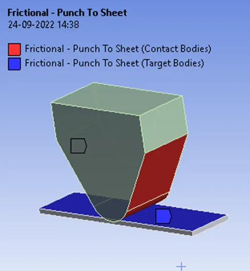
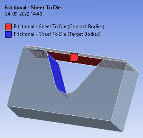
Frictional- Punch to Sheet and Sheet to Die
This state is known as “sticking.” The model defines equivalent shear stress (shear stress refers to cases where the deforming force is parallel to a surface) at which sliding on the geometry begins as a fraction of the contact pressure. Once the shear stress is exceeded, the two geometries will slide relative to each other. The coefficient of friction can be any nonnegative value, here we take it as 0.1, Similar parameters are followed for copper alloy and Magnesium alloy.
shear stress, the force tending to cause deformation of a material by slippage along a plane or planes parallel to the imposed stress.
Meshing Details
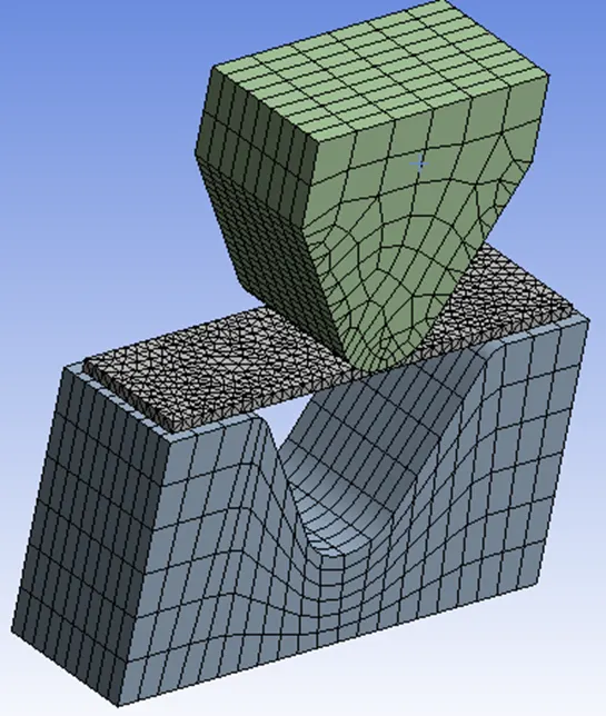
For the meshing part of default solver settings, the ANSYS solver will use the default or recommended mesh value for the model. In this case, since the model looks non-linear with less cross-section and complex geometries take element size as Default, hence reducing the element size at the contact surfaces is of much concern for us to achieve precise simulation results for our challenge. Similar parameters are followed for copper alloy and Magnesium alloy.
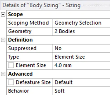
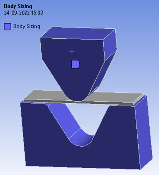
Body Sizing for 2 bodies i.e. Punch and Die at 4mm Element Size
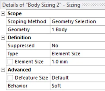
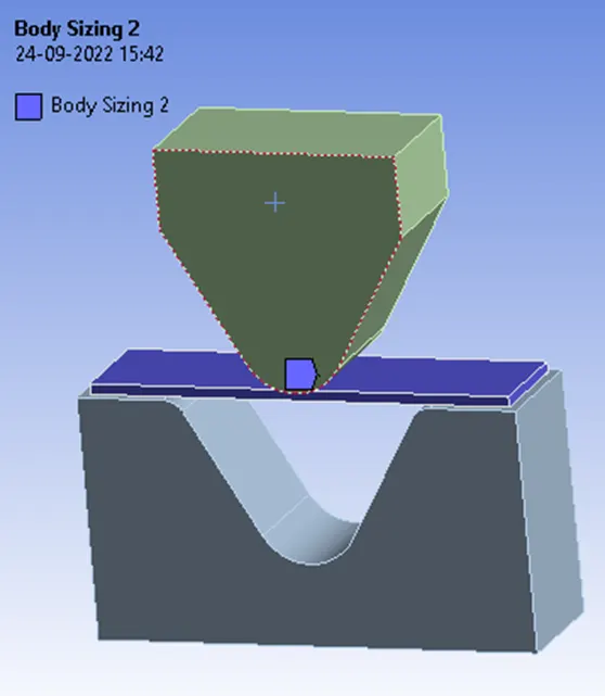
Body Sizing for 1 body i.e. Sheet at 1mm Element Size
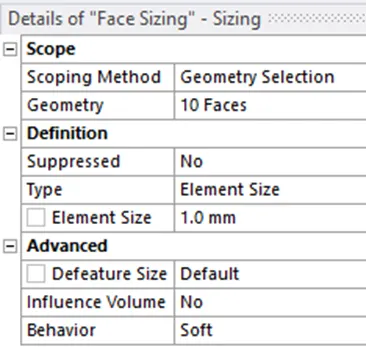
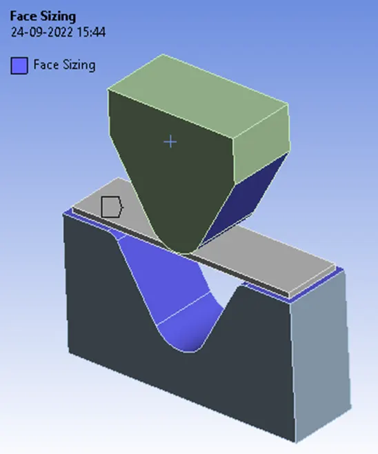
Face Sizing for 10 faces in Punch and Die at 1mm Element Size
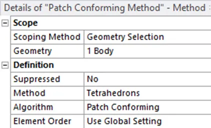
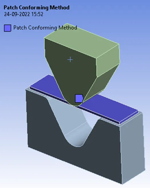
Patch Conforming Method for Sheet
Generated Mesh
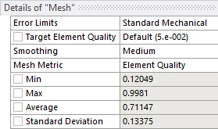
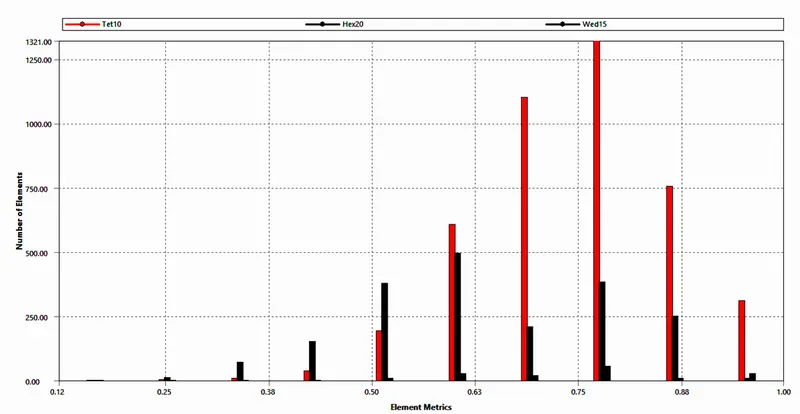
Mesh Metric:
Element Quality
The Element quality option provides a composite quality metric that ranges between 0 and 1 and this metric is based on the ratio of the volume (or area) to the square of the edge length.
So, a Value of 1 indicates a perfect cube or square or triangle or hexagon or quad while a Value of 0 indicates that the element has a zero or negative volume
Boundary Conditions
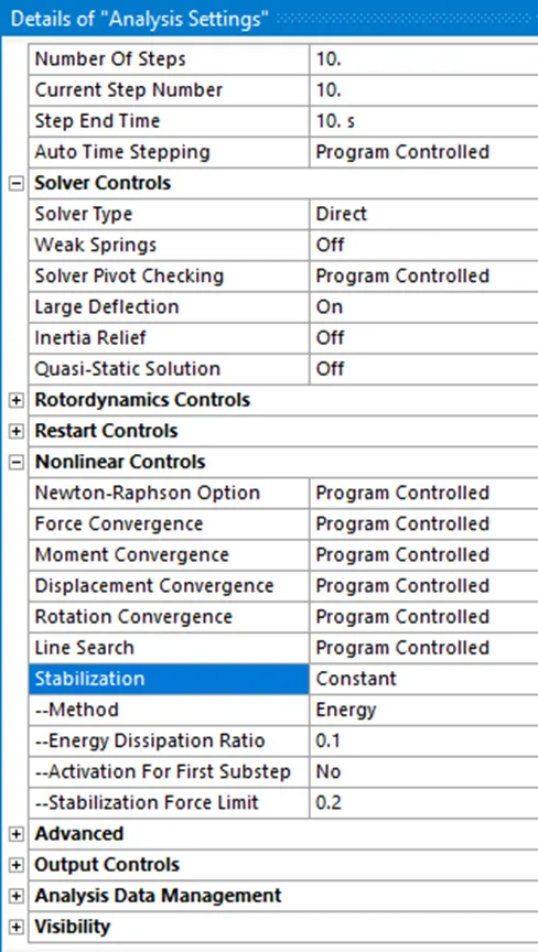
Analysis settings:
The Time Step controls of Analysis settings are crucial for Convergence of Force and Criterion values /curves as this helps the solver converge without any issues.
If we take a smaller time step the solver finds it easy to start with the initial calculation and slowly increases to its maximum time step which helps the solver converges faster without any issues. So always keep this in mind case you are experiencing any convergence issues try to reduce the time step values and start with a less value so that it helps the solver converge faster. Similar parameters are followed for copper alloy and Magnesium alloy.
Load Displacement Settings
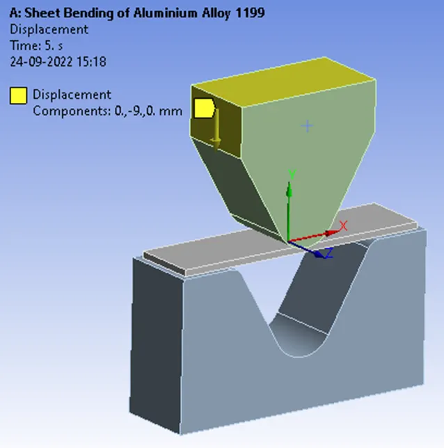
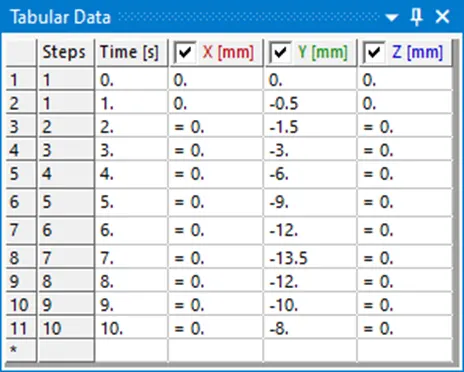
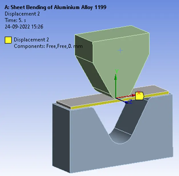
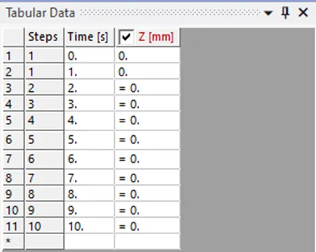
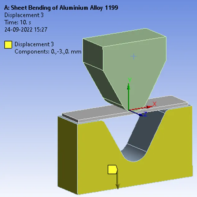
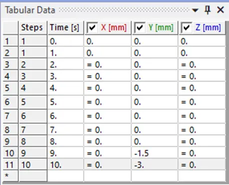
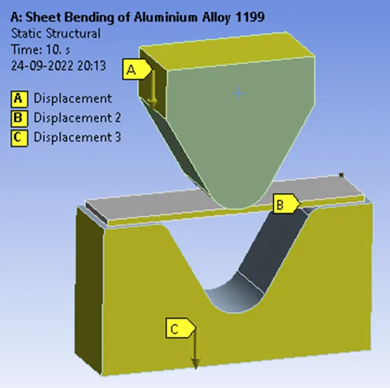
As the Punch advances forward bending the sheet following the impact on the die needs to be reverted back, for this sequence of steps the displacements for punch, sheet and die are tabulated. Similar parameters are followed for copper alloy and Magnesium alloy.
For punch
For Sheet
For Die
Simulation Results For Aluminium Alloy 1199
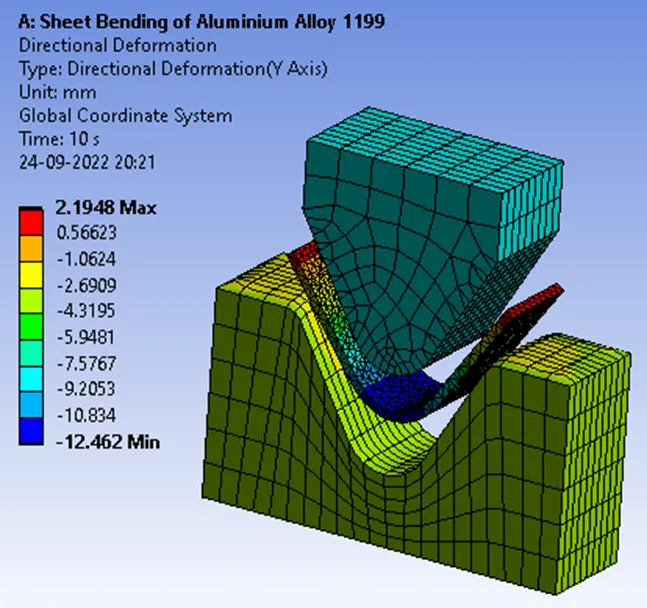
Total Deformation in the Y direction
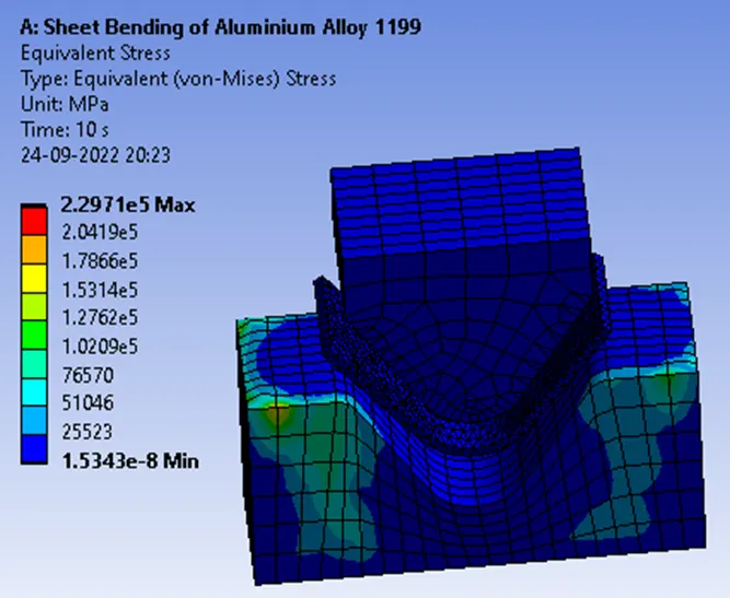
Equivalent stress
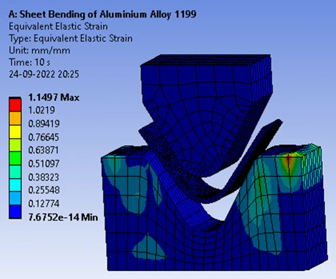
Equivalent elastic strain
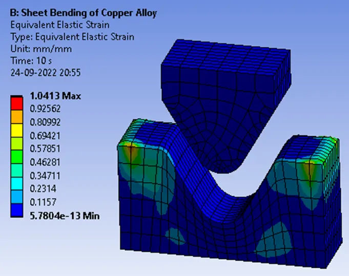
Simulation Results for Copper Alloy
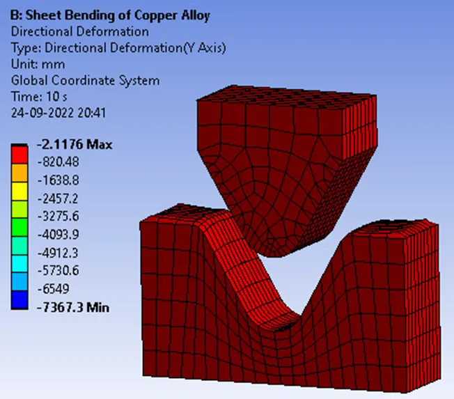
Total Deformation in the Y direction
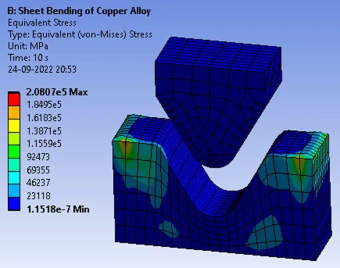
Equivalent stress
Equivalent elastic strain
Simulation Results for Magnesium Alloy
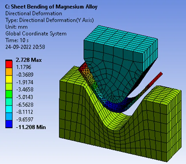
Total Deformation in the Y direction
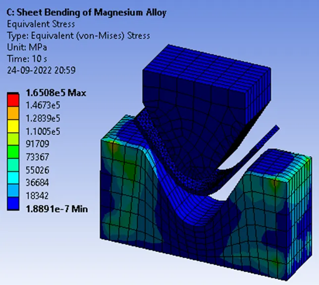
Equivalent stress
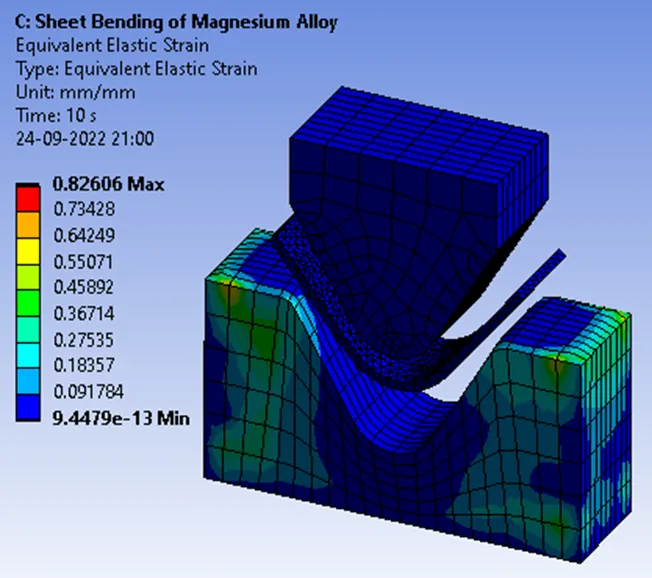
Equivalent elastic strain
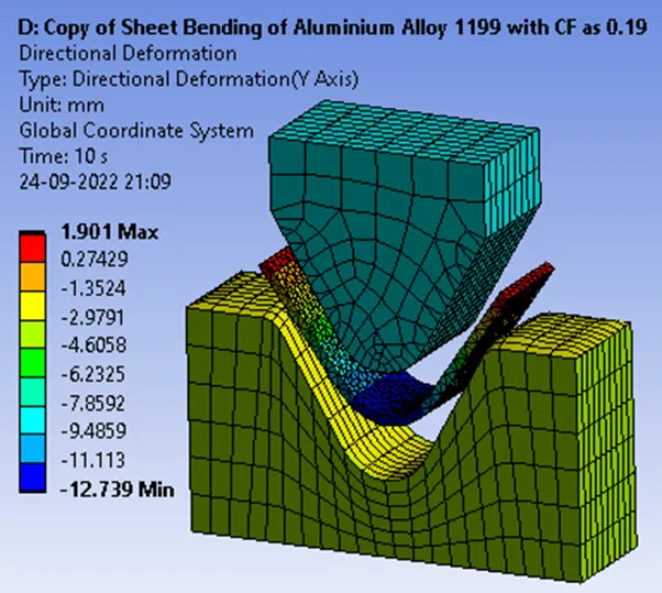
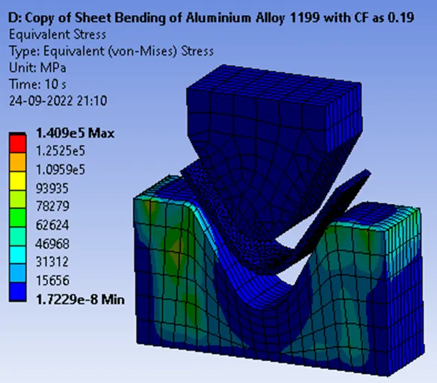
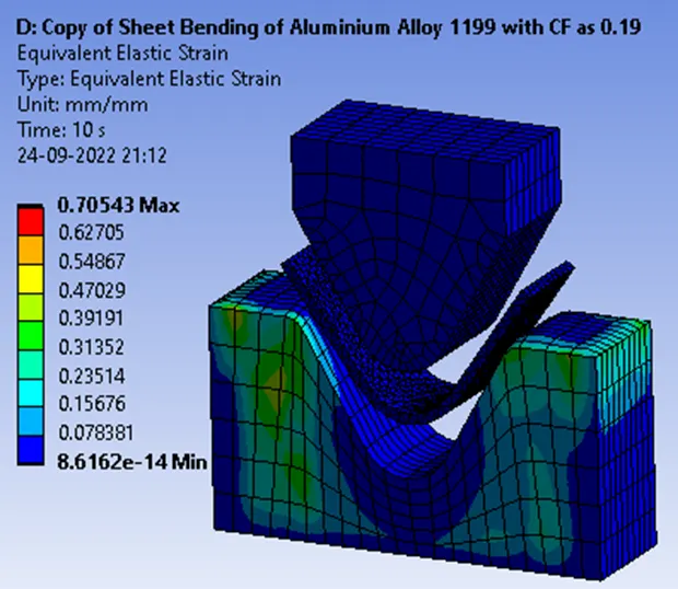
Case 2: With the material as Aluminium Alloy 1199 and changing the friction coefficient to 0.19
Simulation Results
Total Deformation in the Y direction
Equivalent stress
Equivalent elastic strain
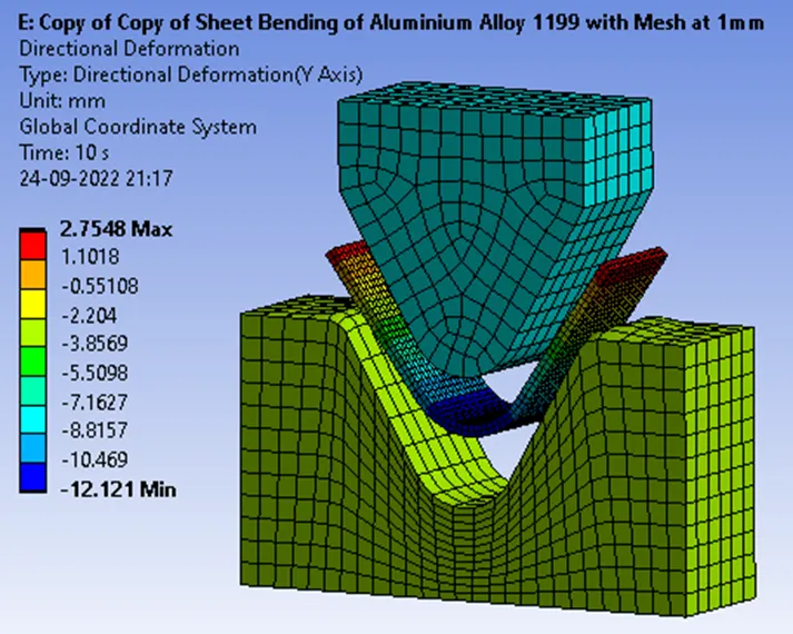
Case 3: Refine the mesh on the Aluminium Alloy Sheet by 1mm as Element Size.
Simulation Results
Total Deformation in the Y direction
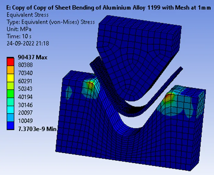
Equivalent stress
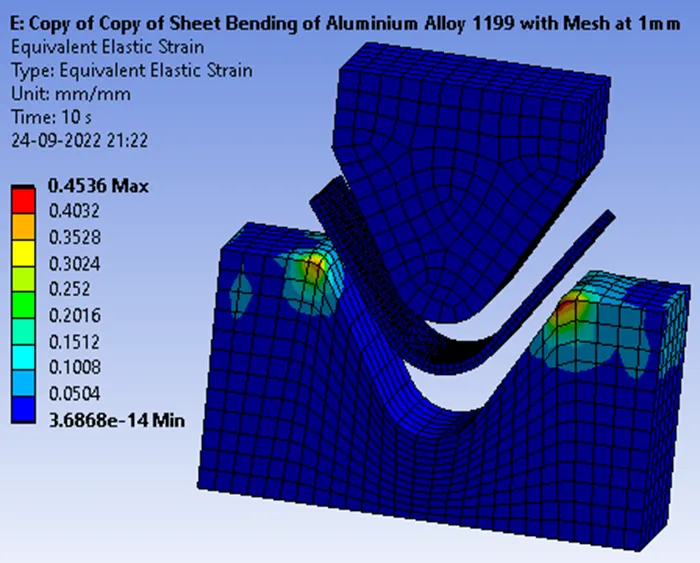
Equivalent elastic strain
Concluding Result.
From the above-tabulated results, we can compare our results considering three material properties of Youngs Modulus, Tangent Modulus and yield strength with Total deformation and Equivalent Stress.
Why?
Because we have taken the 3 Non-Linear Materials which are unpredictable and a new material property called Tangent modulus is used.
Ok, what is this Material property called Tangent Modulus?
Tangent modulus calculations are recommended for non-linear materials.
In solid mechanics, the tangent modulus is the slope of the stress-strain curve at any specified stress or strain. Below the proportional limit (the limit of the linear elastic regime) the tangent modulus is equivalent to Young's modulus. The Ramberg–Osgood equation relates Young's modulus to the tangent modulus and is another method for obtaining the tangent modulus.
The tangent modulus is mostly used to describe the stiffness of a material in the plastic range.
So it is clearly observable that if the Tangent Modulus slope is below the proportional limit it is equal to Young's modulus and also Ramberg–Osgood equation relates or equates Young's modulus to the tangent modulus.
Hence, for our comparative analysis, we consider material properties Young's modulus and Yield strength for all the 3 cases of nonlinear Materials.
Why Yield Strength?
Equivalent stress is the type of stress chosen for the Yield Criterion. Engineers use this simple scalar value to determine if the material has yielded or failed.
|
Material Specifications for |
Density (Kgm^-3) |
Young’s Modulus [MPa] |
Bulk Modulus [MPa] |
Shear Modulus [MPa] |
Yield Strength [MPa] |
Tangent Modulus [MPa] |
|
Case I Aluminium Alloy 1199 |
2770 |
62000 or 6.2e10 pa |
60784 or 6.0784e10 pa |
23308 or 2.3308e10 pa |
140 or 1.4e8 pa |
209.46 or 2.0946e8 pa |
|
Case II Copper Alloy NL |
8300 |
110000 or 1.1e11 pa |
114580 or 1.1458e11 pa |
41045 or 4.1045e10 pa |
280 or 2.8e8 pa |
1150 or 1.15e9 pa |
|
Case III Magnesium Alloy NL |
1800 |
45000 or 4.5e10 pa |
50000 or 5e10 pa |
16667 or 1.6667e10 pa |
193 or 1.93e8 pa |
920 or 9.2e8 pa |
For Case 1
|
Analysing Cases for |
Total Deformation on Y-Axis (mm) Max |
Equivalent Stress [MPa] Max |
Equivalent Elastic Strain [MPa] Max |
|
Case 1 Aluminium Alloy 1199
|
2.1948 |
2.2971e5 or 0.22971 |
1.1497 |
|
Case 1.2 Copper Alloy
|
-2.1176 |
2.0807e5 or 0.20807 |
1.0413 |
|
Case 1.3 Magnesium Alloy
|
2.728 |
1.6508e5 or 0.16508 |
0.82606 |
From case 1 Aluminium Alloy 1199 material the Equivalent stress is less compared to yield strength and young’s modulus which clearly shows that the material is elastic or Flexible and can withstand further force/Load.
From case 1.2 Copper Alloy material the Total Deformation is in Negative Value because of compressive stress that clearly concludes our result Comparatively with the Material Properties Table. Equivalent stress is also less compared to yield strength and young’s modulus which clearly shows that the material is elastic or Flexible and can withstand further force/Load.
From case 1.3 Magnesium Alloy material the Equivalent stress is less compared to yield strength and young’s modulus which clearly shows that the material is elastic or Flexible and can withstand further force/Load.
Thus, the Sheet Metal for all the 3 cases is Clearly Elastic and Flexible where small deformations are reverting back. Good for our design Considerations
For Case 2
|
Analysing Cases for |
Total Deformation on Y-Axis (mm) Max |
Equivalent Stress [MPa] Max |
Equivalent Elastic Strain [MPa] Max |
|
Case 1 Aluminium Alloy 1199 with a Coefficient of Friction of 0.1
|
2.1948 |
2.2971e5 or 0.22971 |
1.1497 |
|
Case 2 Aluminium Alloy 1199 with a Coefficient of Friction of 0.19
|
1.901 |
1.409e5 or 0.1409 |
0.70543 |
What is the Coefficient of Friction?
The ratio of the friction force to the normal force experienced by a body moving on a dry, non-smooth surface.
From our Analysis results table as the frictional Coefficient value increases, Equivalent stress and Equivalent Strain decreases because the Frictional force is Smaller than the Normal force due to high elastic or flexible Aluminium Alloy 1199 material properties.
For Case 3
|
Analysing Cases for |
Total Deformation on Y-Axis (mm) Max |
Equivalent Stress [MPa] Max |
Equivalent Elastic Strain [MPa] Max |
|
Case 1 Aluminium Alloy 1199 Sheet with Mesh of Element size as 1mm
|
2.1948 |
2.2971e5 or 0.22971 |
1.1497 |
|
Case 2 Aluminium Alloy 1199 Sheet with Mesh of Element size as 0.6mm |
2.7548 |
90437 or 9.0437e10 Pa |
0.4536 |
As the mesh gets finer, the results will become more accurate. From the above table, we can see that as the mesh gets finer the results are increased meaning that the results get more accurate.