Week 2 Bevel Gear Challenge
AIM:
To perform a grid dependency test on a bevel gear to get optimum results
BEVEL GEAR :
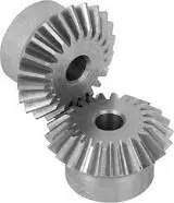
Bevel gear are gears where the axies of the two shafts intersects and the tooth-bearing faces of the gears themselves are conically shaped. Bevel gear are most often mounted on shafts that are 90 degress apart but can be designed to work another angles as well. In the efficiency a straight bevel gear has a 10:1 ratio range. A atraight bevel gear is approximately 96% efficient pwr stage
The pitch angle of a gear is the angle between the face of the pitch surface and the axis. The most famillar kinds of bevel gear have pitch angle of less than 90 degrees and therefore are cone shaped. This thype of bevel gear is called external because the gear teeth point outward. Miter gears can't be used to change speed. However the 90 degree intersecting axes of miter gears results in highly efficient operations and hence these gears are used in applications that demand high efficiency.
GRID DEPENDENCY:
- Grid dependency is the method used in CAE to get optium results by reducing mesh density in a given component.
- Grid dependency, mesh refinement or scalling are similar words usded in FEA AND CFD analysis.
- Initially FEA process starts with the default or coarse mesh aftetr obtaning the results, a mesh in refined in area of interest which will give appropriate results.
- The process is followed until the user gets optimised results for give problem. When there is no siginificant change in equivalent stress and equivalent strain we can say that the mesh refinement is achived
- further mesh refinement will not show drastic change in values of stress and strain.
- When the mesh size become smaller it will lead to higher computational time. there can be an issue with force convergence as well.
- The results obtained by mesh refinement give accurate result close to realistic results.
- Grid dependency means not only reductionof mesh size but we can achive it by linear or quadric elements it also depends on geometry as well.
PROCEDURE:
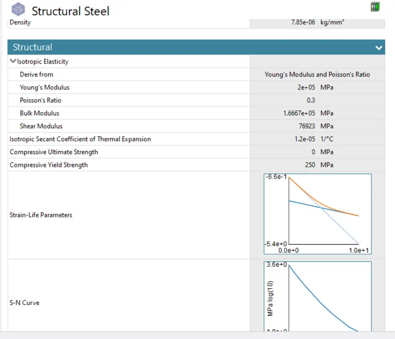
- We have taken sturctual steel as material for bevel gear
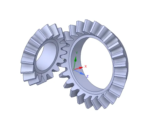
- After selecting material import geometry as Skill_Lync_Bevel_Gear.IGS
- Go to the model
- According to the challenge these are three defferent mesh size case,that size is 6mm,5mm and 4mm
- Select the geometry for both gears and rename it was SMALL AND BIG gear
- Give the material assignment to both gears as per case.
- From the project tree select connection and create contacts.
geometry
contacts
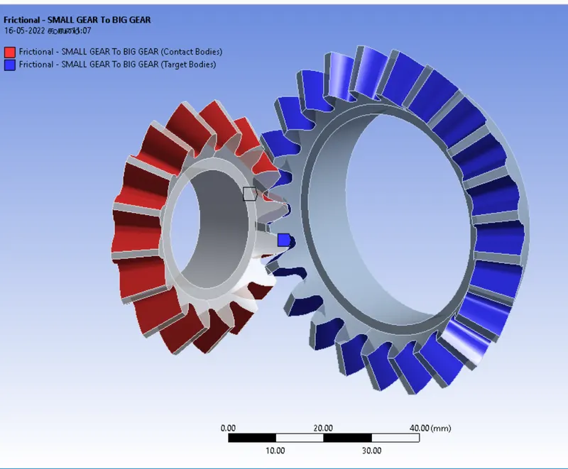
- For defining contacts between two gears select faces of left gears as contacts and of gear as target for connection.
- There are all gears must selected.
- Select contact type = Frictional because due to friction there will be movement between gears.
- select Behavior = symmetric
- Select Formation = Augment legrange. As soon as teeth come in in contact it will tend to move from position. So Augment Legrange formulation reduce vibration and penetration and increase stiffness of gears.
- Select interface Treatment = Adjust to touch because if there is a gap between them or initial penetration than this setting will help to adjust it and any error can be avoided.
- Select inner face of each gear and give it revolute joint as descriped in above image.
- For frame of reference for gear select connection type = Body To Ground for both of the gears.
- We can see that in revolute joint, degree of freedom for gears automatically set to its axis in RZ direction.
BOUNDARY CONDITIONS:
- Here we are going to look at contacts forces, traces and stress developed for 1 revoiution of gear. So for 180 degree angle in analysis setting give values as given below
No steps = 6
Auto time Stepping = ON
Defined by = TIME
initial Time Step = 0.25 s
Minimum Time Step = 0.1 s
Maximum Time Step = 1 s
- Select all 6 steps and select Large Deflection = ON in slover controls.
other Bountry condition for joint are as given below - joint load
Joint Rotation = Ground To Big gear
Type = Moment
Magnitude = Tabular Data
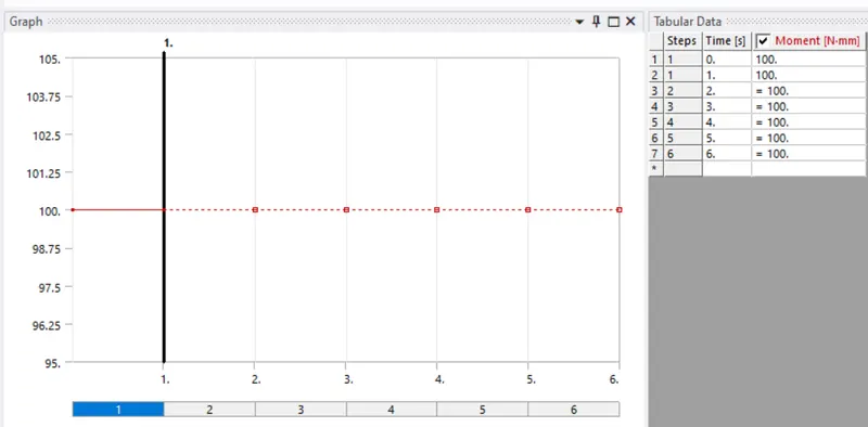
Tabular data
- Joint Load
Joint Rotation = Ground To Small gear
Type = Rotation
Magnitude = Tabular data
Tabular data
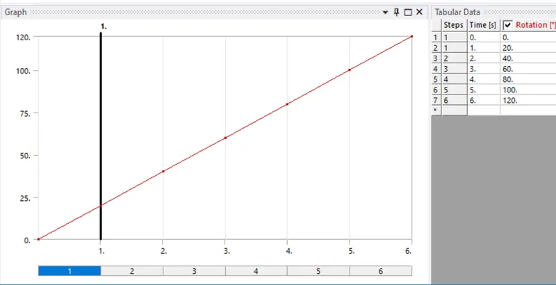
SOLUTION:
- After giving proper boundary condition create desired solution for output results.
- Create solutions for Equivalent srtess, Total deformation and Stress intensity
- Also give contact tool and create solution for contact status and pressure.
RESULTS :
Case 1 ,Mesh Size = 6 mm
Mesh
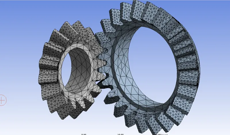
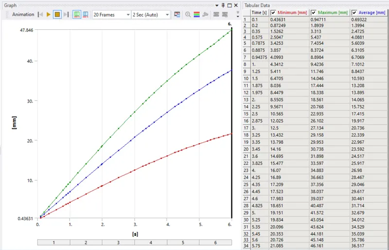
Total deformation and graph
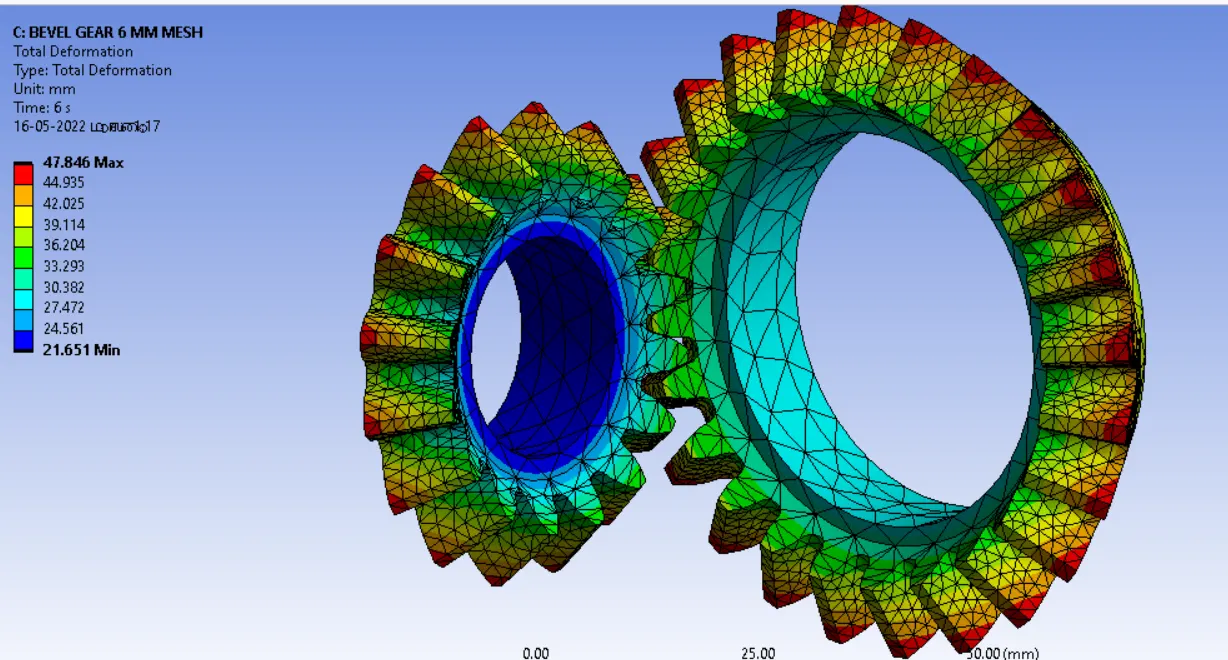
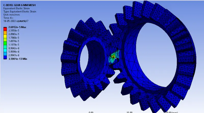
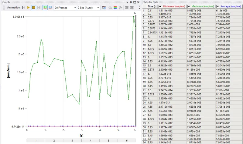
Equivalent Strain and graph
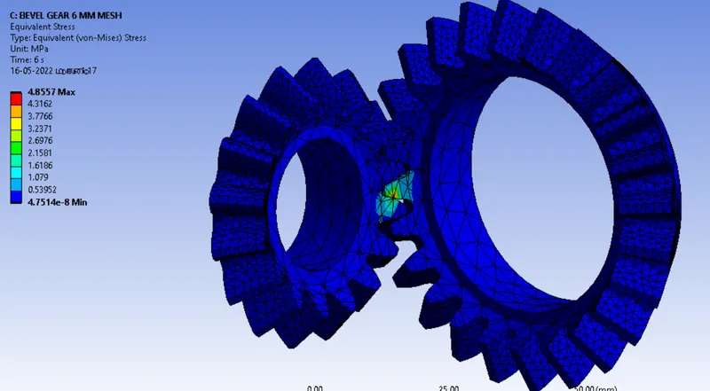
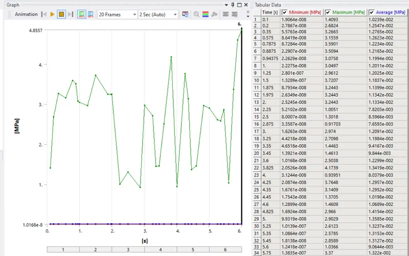
Equivalent srtess and graph
Case 2 ,Mesh Size = 5 mm
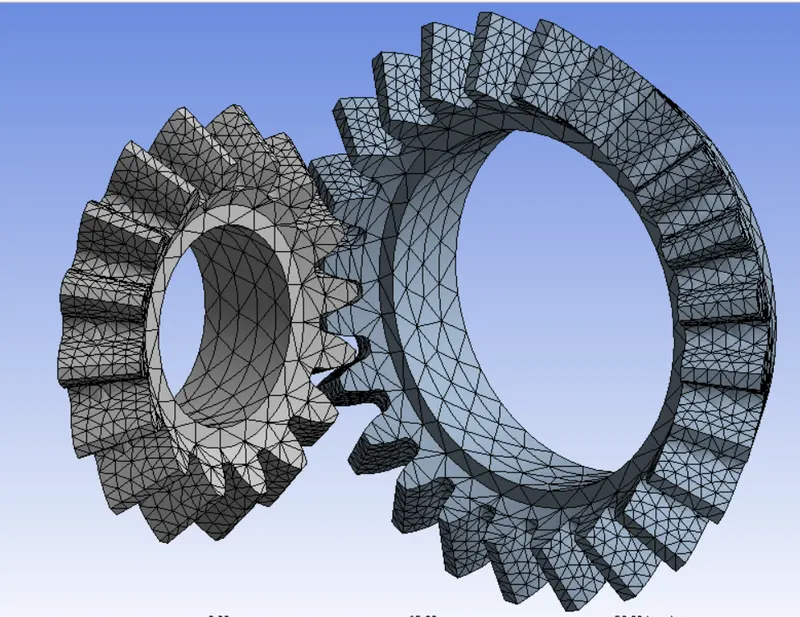
Mesh
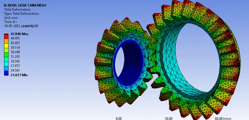
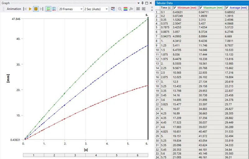
Total deformation and graph
Equivalent Strain and graph
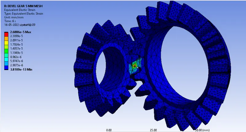
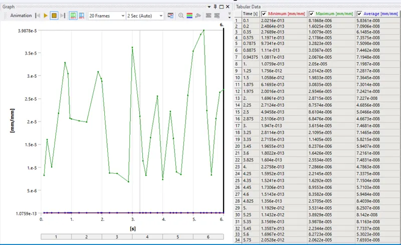
Equivalent srtess and graph
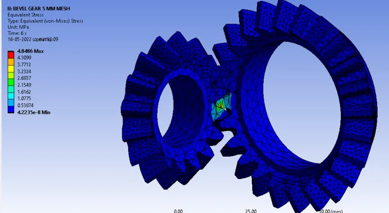
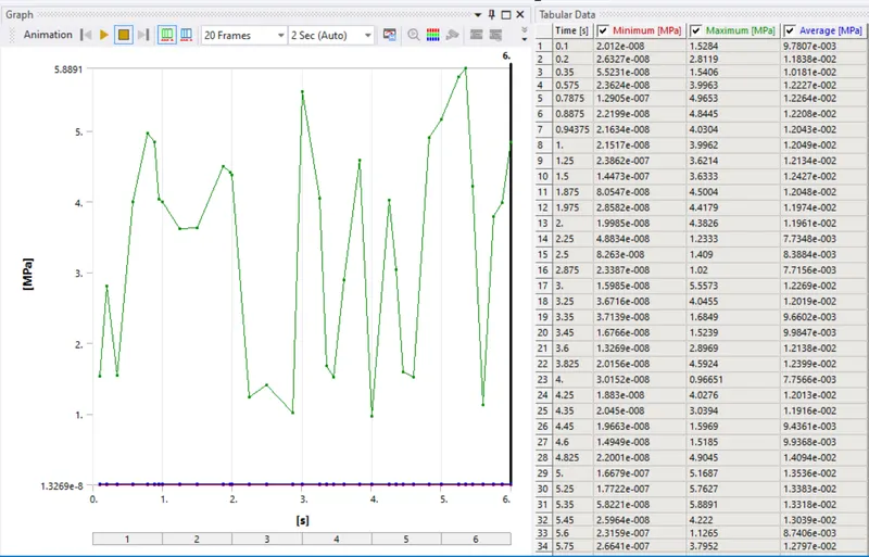
Case 3 ,Mesh Size = 4 mm
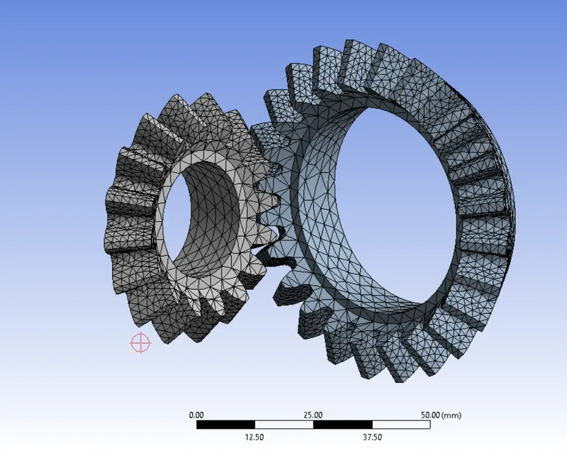
Mesh
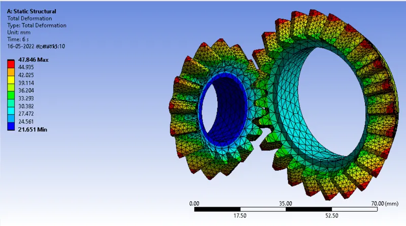
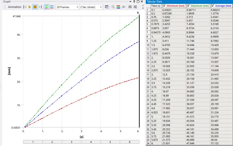
Total deformation and graph
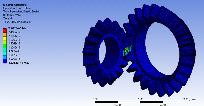
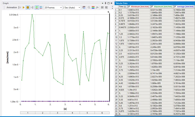
Equivalent Strain and graph
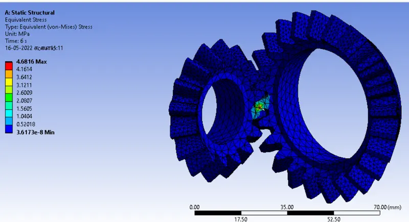
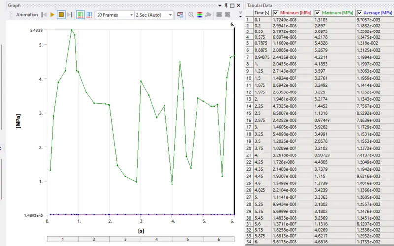
Equivalent srtess and graph
| CASE |
SIZE MM |
TOTAL DEFORMATION MM |
EQUIVALENT STRAIN MM |
EQUIVALENT STRESS MPA |
| 1 | 6 | 47.846 | 2.6952e-5 | 4.8557 |
| 2 | 5 | 47.846 | 2.6886e-5 | 4.8486 |
| 3 | 4 | 47.846 | 2.7078e-5 | 4.6816 |
CONCLUSION:
In this simulation, total deformation is similar then all cases. The values of equivalent elastic srtess is decreasing when we decreasing the mesh size. In the case 1 and 2 there is almost similar in the equivalent stress and strain in the simulation. The case 2 and 3 are more diffrence in the equivalent stress and strain. Same as stress and strain , equivalent stress value is also change with the mesh size. We can clearly see that the result obtained with 4mm mesh is a bit similar to 5mm mesh so we we can say that 4mm mesh results are accurate and close to realistic results.
FILE LINK
https://drive.google.com/file/d/1EP8lvRYUkIwrJsRGv_JtT1ySlFcFKqZB/view?usp=sharing