Week 2 Bevel Gear Challenge
AIM: To perform the simualtion of Bevel Gear
GRID DEPENDENCY:
- Grid independence study is performed to eliminate/reduce the influence of the number of grids/grid size on the computational results. And it is always good practice to follow this for every individual geometry, which is tedious. The grid independence for one geometry will be applicable only for that geometry.
- The main flaw of the finer mesh flow has the elements and node size will increase compared to the coarse mesh size and it we take a lot of time to evaluate the result. As this test will benefit for an accurate result because of the high-density mesh.
PROCEDURE:
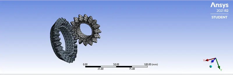
- The bevel gear is shown below:
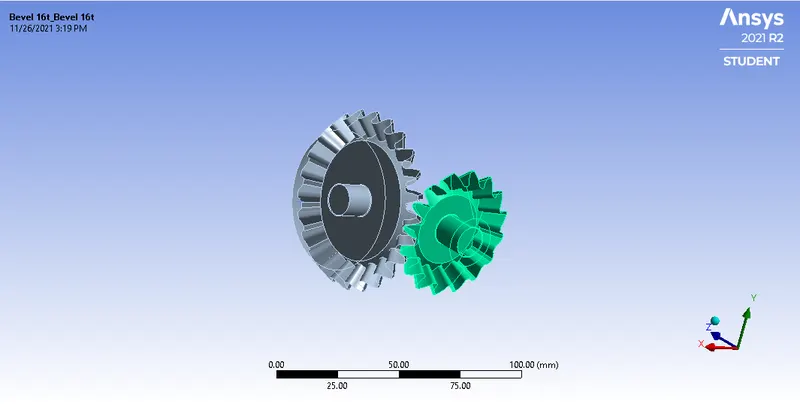
- Now we have to perform the simulation on this. So we have to mesh this component with given element sizes whic are 6mm, 5mm, 4mm.
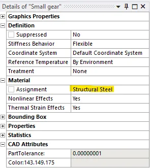
- Here we are using the material as a Structural Steel.
- Now first we will edit the geometry in Spaceclaim
- So as we seen in the diagram we are only interested in tooth so we will remove the surface which we do not required. So for that select he surface and then create a circle on it after that use pull option to remove the part. So the final component will look like this:

- Now after that go to the model in workbench and edit it to perform the other operations.
- So first we are assigning the material to the component, material we choosing in structural steel. Its added in geometry section.
- Now after this we are performing connection on the it.
- So for that we are selecting the tooth of the both gear as contact and target bodies. Shown below:
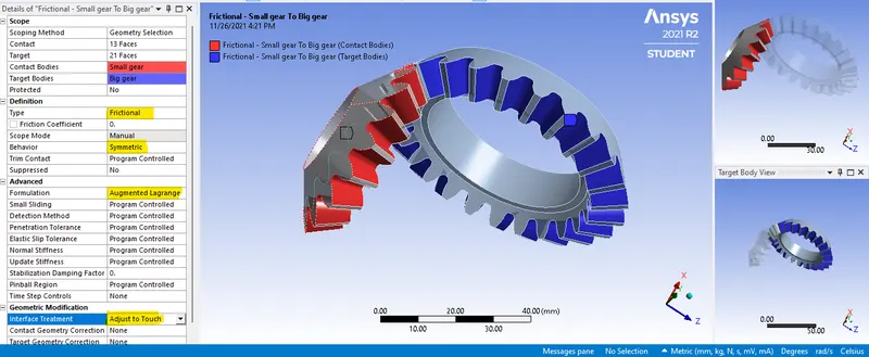
- And also change the seeting as highlighted above.
- Now after this we will define the joint for the gear, since it is a gear so we are defining revolute join to it.
- To create a joint go to the CONNECTION>INSERT>JOINT and the change the settings as shown in tab and select the surface of the gear as shown:
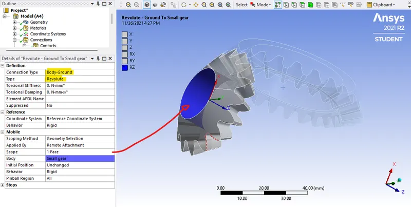
- Create a another joint and do the same with the another gear.
- Now after that we are going to do analysis setting.
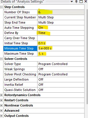
- For setting up the simulation for taking out the result the 6 steps are taken with an auto time step on, defined by time and Initia time step 0.1s, minimum time step 0.005s maximum time step 1s.
- Now after this we will insert the joint loads
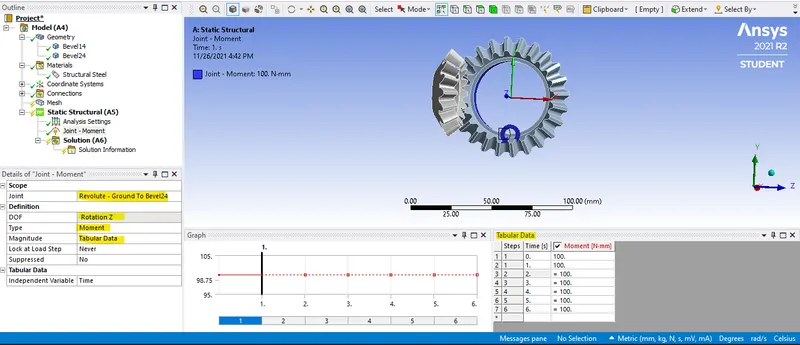
- So first we are going to give a moment of 100N to the gear with 24 tooth . As shown
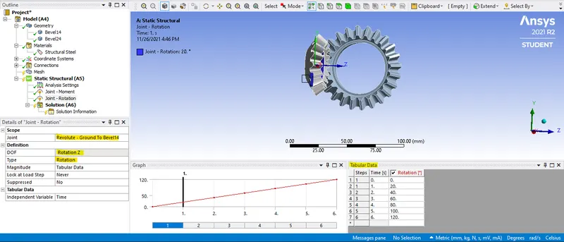
- After this we are going rotate the gear with 12 tooth with with the angle of 20 degrees at each step. As shown:
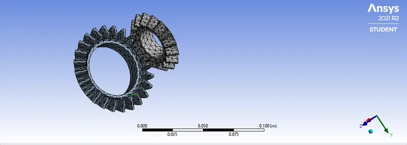
- Now after this we will mesh the component with mesh size and 6mm, 5mm, 4mm and comapre the results.
MESH SIZE: 6mm
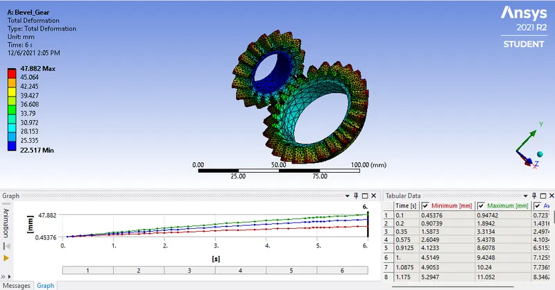
Total Deformation:
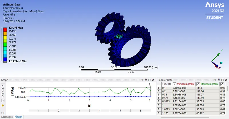
Von-Mises stress
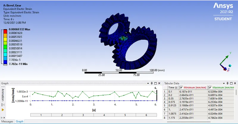
Equivalent elastic strain
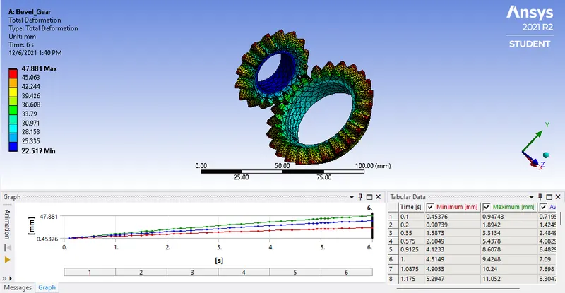
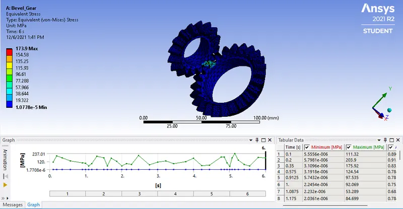
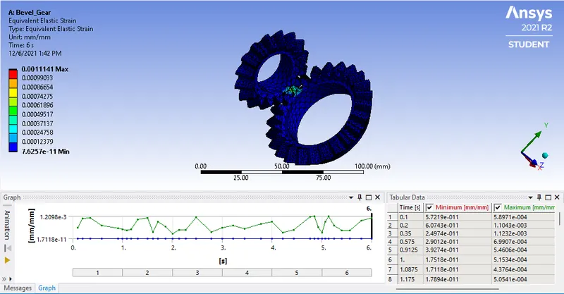
MESH SIZE: 5 mm
Total Deformation:
Von-Mises stress
Equivalent elastic strain
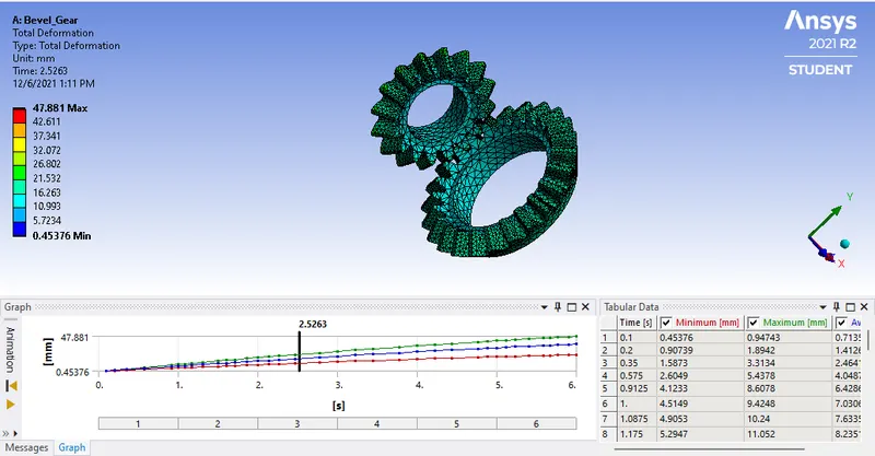
MESH SIZE: 4 mm
Total Deformation:
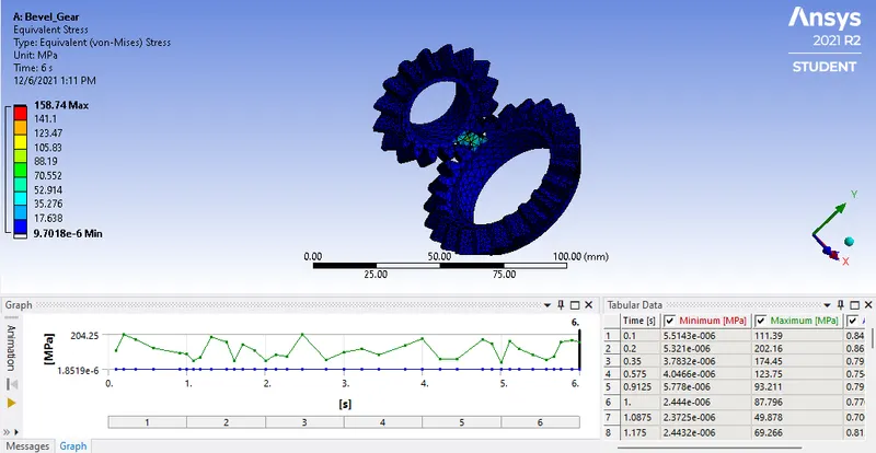
Von-Mises stress
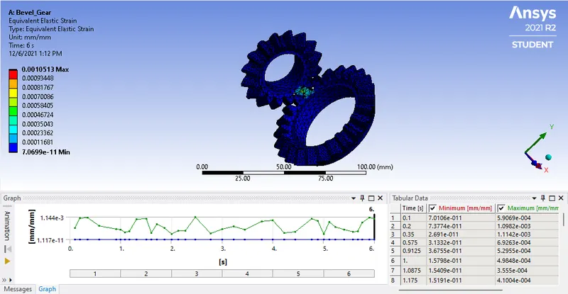
Equivalent elastic strain
COMPARISON:
| Sr No | Mesh Size (mm) | Total Deformation(mm) | Von-Mises stress(MPa) | Equivalent elastic strain |
| 1 | 6 | 47.88 | 124.16 | 0.00069 |
| 2 | 5 | 47.88 | 173.9 | 0.00111 |
| 3 | 4 | 47.88 | 158.74 | 0.00105 |
CONCLUSION:
- Total Deformation is Similar in all three cases.
- The values of Equivalent Elastic Strain ischanging when we decrease the mesh size, there is a small change in values of strain.
- Same as strain, Equivalent Stress value also changes with the mesh size.