Week 2 Bevel Gear Challenge
GRID DEPENDENCY TEST ON BEVEL GEAR
Aim
To model a simple bevel gear system and perform grid dependency test at mesh size of 6mm ,5mm and 4mm.
Theory
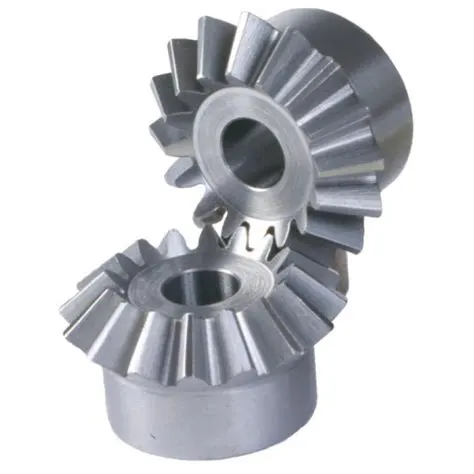
Bevel gears are power transmission parts first employed to modify the direction of shaft rotation and to reduce the speed and improve the torque between non-parallel spinning shafts. They are utilized on shafts with intersecting axes and, in particular, issues on shafts whose axes do not cut across. Shafts are always, but not presently, perpendicular. Essentially, bevel gears can be categorized by their tooth shape, either curved or straight.
Bevel gears are types that utilize two conical forms of toothed wheels to transmit energy between axes that are cut within the same space; however, hypoid gears can transmit energy between two axes that cross each other.
The teeth of a bevel gear can be either spiraled or straight, which is also introduced as a conical helix. Several kinds of gears can be classified not only based on the width of their tooth but also on the tooth face width or the circular pitch of the center.
Bevel gears see significant applications in construction equipment, automotive drivetrains, helicopter transmissions, marine thrusters, locomotives, etc. They are utilized in various industrial applications too, as assembly-line transmissions, escalator drives, and wind-tower gearing, for instance. Even a single hand-drill uses a 90° form of bevel gear.
Grid Dependency Test
Grid dependency test investigates how the solution depends on the grid size by running the simulation with various mesh sizes that is finer the mesh the higher the accuracy of the result but with additional cost on computation time and computational power. Since, solutions are interpolated at the nodes to get an approximate result, higher number of nodes and elements increase the computational time and power required to complete the simulation.
So, the grid dependency test helps in determining optimal mesh size for both accurate results and minimum solver time.
Procedure
- Open a new static structural analysis project in work bench.
- Import the bevel gear geometry in space claim.
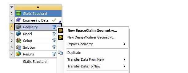
- Double click it to open it in space claim.
- Remove the excess portion in the centre of the gear as it is not our area of interest and will just increase the overall solver time, (Create holes of 45mm dia for the big gear and 25mm dia for the small gear) and pull it)
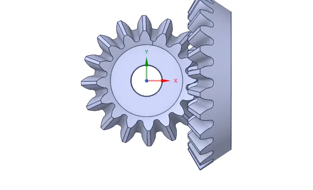
- Open this model in mechanical.
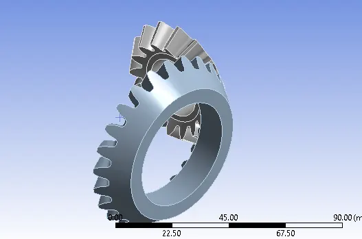
- In Contact Regions, select all the faces of the small gear and big gear appropriately for contact and target body.
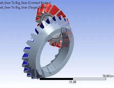
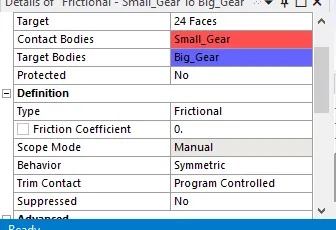
- Create the rigid revolute joints for both gears as well.
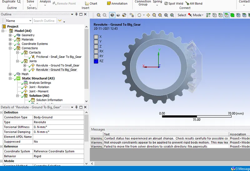
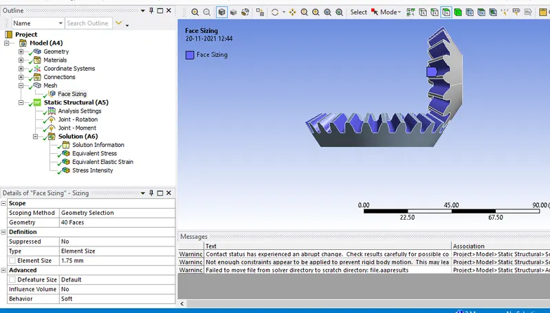
- In mesh, set the default length as 6mm and create a face sizing for the teeth faces
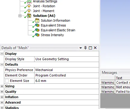
- Select all the faces of both gears and set it to 1.75mm
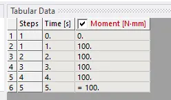
- Define a moment of 100N-mm for the small gear and a rotation of 0-120 for the big gear.(Make sure that the gear rotates in the proper direction and adjust your values or coordinate system to fix it)
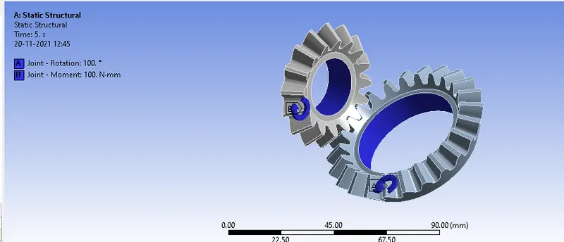
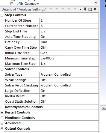
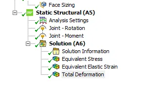
- Set your Analysis settings as follows and run the simulation. (If you get convergence errors try further reducing the timestep)
Create the appropriate output blocks for stress, strain and deformation.
- Repeat the process for 5 mm and 4mm mesh sizes and compare the results and time taken.
Post Processing
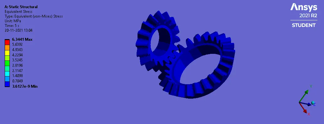
6mm
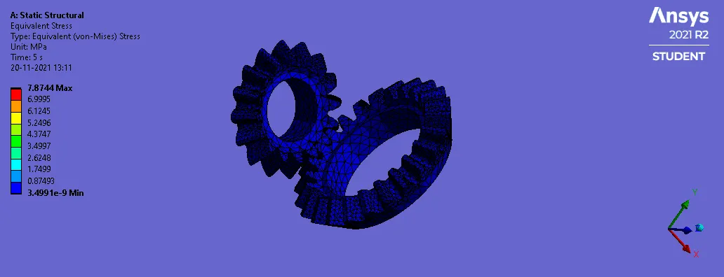
5mm
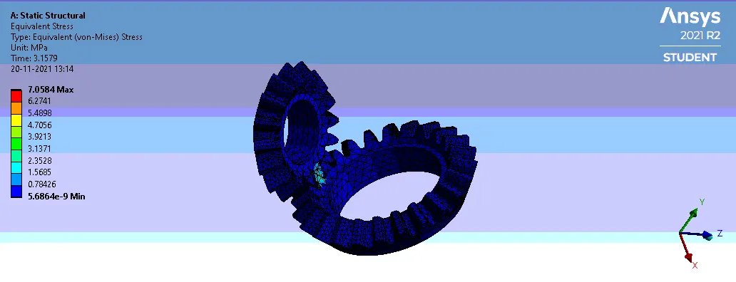
4mm
Tabulated Results
|
Mesh Size |
6mm |
5mm |
4mm |
|
Stress (Mpa) |
5.9573 |
7.8743 |
7.0314 |
|
Strain |
3.25 e^-5 |
4.0026e^-5 |
3.6691e^-5 |
|
Deformation(mm) |
57.053 |
57.053 |
57.053 |
|
Solver Time (s) |
2655 |
3133 |
3505 |
- It can be observed that the 4mm mesh, being the most refined, gives the most accurate results but takes a significantly longer time compared to the 5mm and 4mm mesh.
- The 5mm mesh size gives values similar to that of the 4mm mesh but takes a much lower time of 2337.812 seconds and should be the recommended mesh size since it takes a lower time to solve for similar results.
- If constrained for time, a mesh size of 6mm can be used but care should be taken over the stress levels, possible refinement of lower mesh size near the teeth for better accuracy.
Conclusion
A grid dependency test was performed on a simple Bevel gear system for mesh sizes of 6mm, 5mm and 4mm.It was observed that the 5mm mesh size was optimal considering time and accuracy due to similar mesh sizes in comparison with the 4mm results.
However if constrained for time, refinement of the area near the tooth and going with a coarser mesh elsewhere can be considered.