Week 2 Bevel Gear Challenge
AIM
1)Write a few words on what a grid dependency test is and its use.
2)Perform a grid dependency test for the Bevel gear simulation for mesh sizes of 6,5 and 4 mm
3) Solve for Von-Mises stress, Equivalent elastic strain and Total Deformation using the previously mentioned mesh sizes.
4) Present your findings in an organized manner.
Objective:In this test we have to perform the grid dependency test on the Bevel gear with different mesh size of 4,5,and 6 and we have to select will is better mesh.
Grid Dependency:This ia Grid dependency test where the analysis begins a the coarse mesh and we should have to fine the mesh refined mesh we should have to run the simulation and we should run until the results do not change significantly.ie.that mesh is the significant parameter which is used to produce the accurate results.Higher density of the mesh higher the result in the better accuracy .But it consumes the lot of computational time so this test is used to find the accurate result from the coarse to fine.
Procedure:
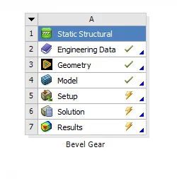
- Open the Static structural in the ANSYS work bench and edit the Engineering Data.
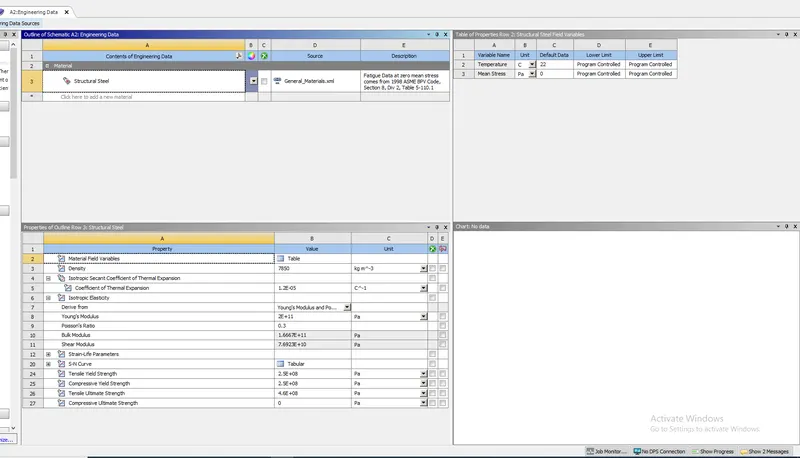
- Give it as structural steel and give the specifications to the structural steel.
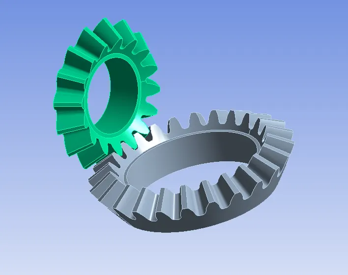
- After that we should have to edit the Geomentry in the Geomentry tab>New space claim we should have to create the holes of diameter of 27,47mm and we should use the pull option and remove the surface.
- We should have to Go the model>edit>click on ok.
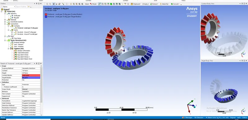
- We should have to give the contacts to the both small and big gear.
- we should go the connector>contact>click on inserts>joints>and select the both contact and surface faces of the component.
- we should have to create the joints for the both Revolute joints for the big and the small gears and we should have to give the direction for the joints of clcokwise and anti clcock wise to the joints.
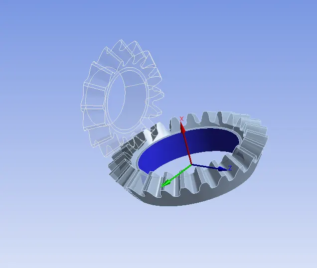
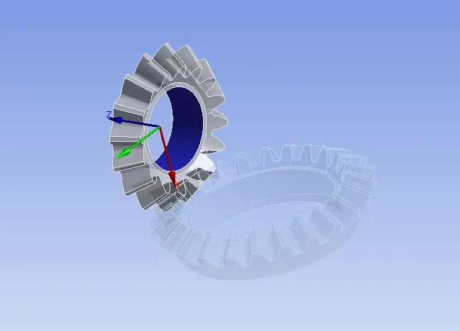
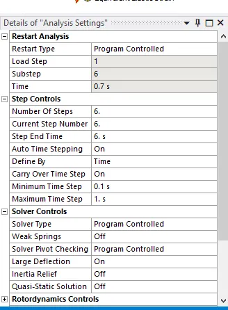
- we should have to give the parameters to the Analysis settings and give the time step and end time and starting time to the model.
- we should have to create the joints load of Moment and give the values for the 6 time steps.
- we should have to create the another joint load and create the rotation for the time steps.
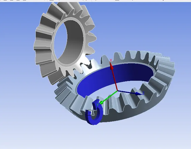
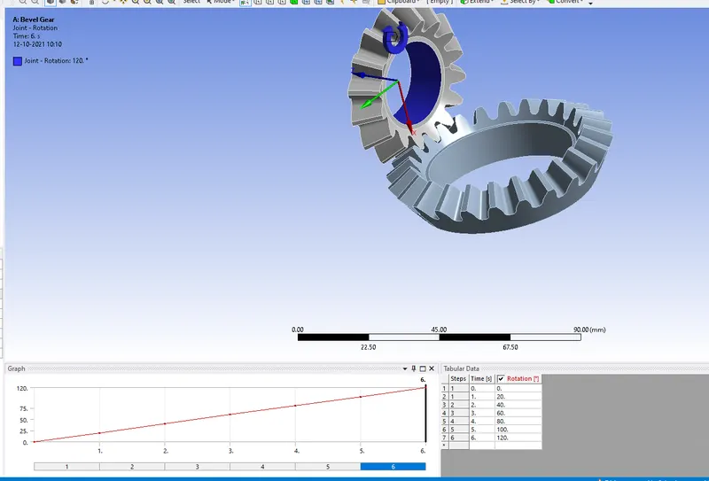
- we should have to give the mesh to the component and having element size as 4,5,6 and we should have to provide the facing size of the model.
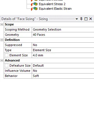
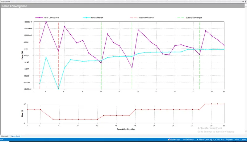
Case 1: Target size=4
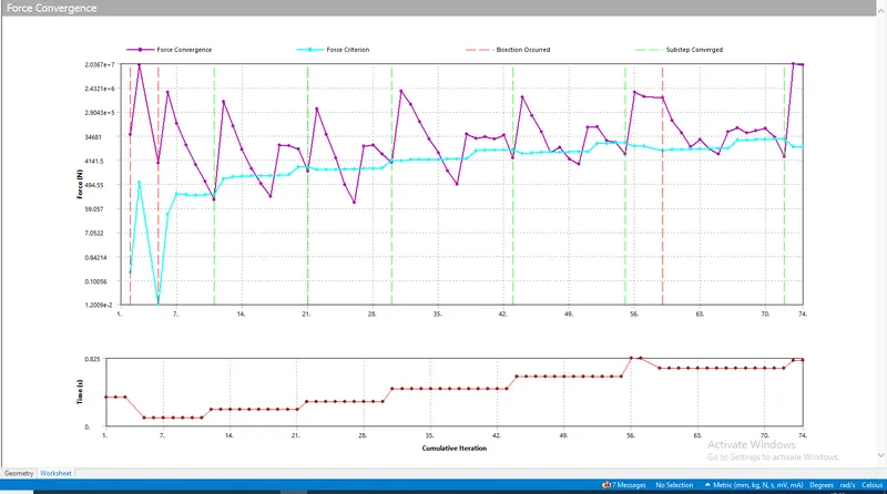
Force convergence
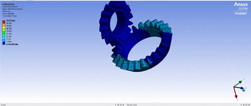
Total Deformation
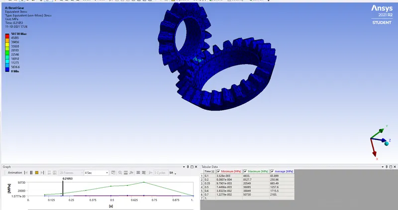
Stress
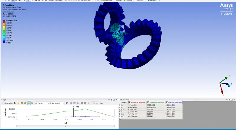
strain
Case 2:5mm
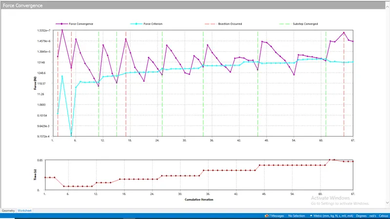
Force convergence
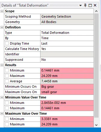
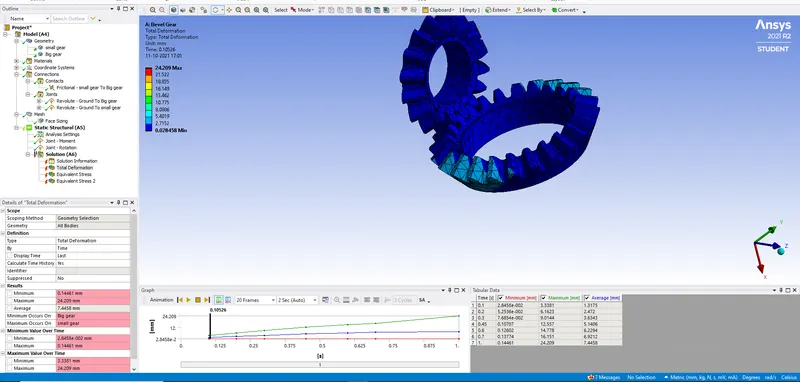
Total deformation
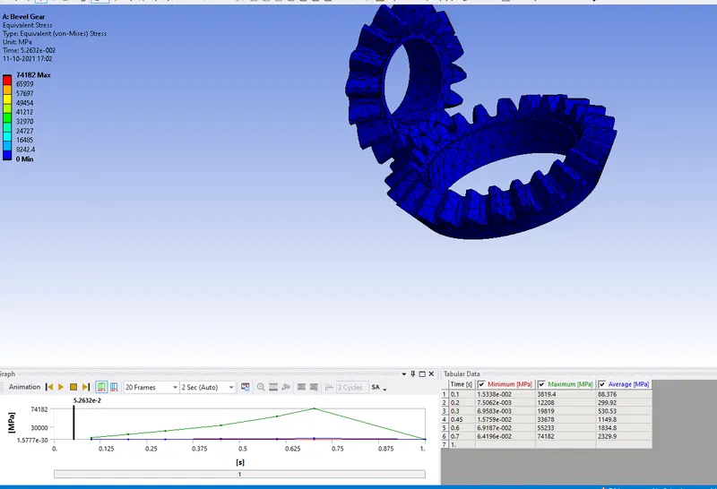
stress
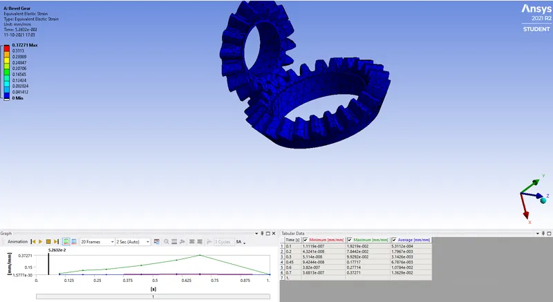
strain
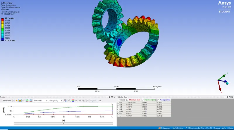
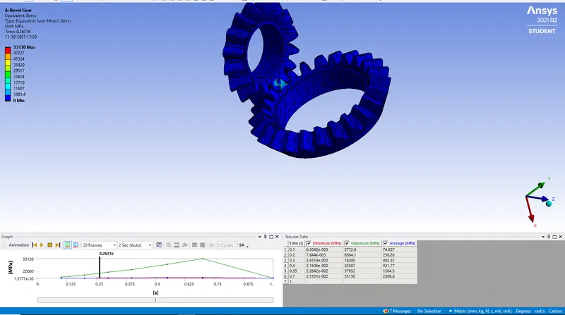
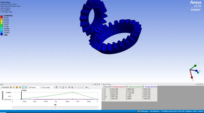
Case 3:Target mesh size =6
Force Convergence
Total Deformation
stress
strain
Results for the above meshing size of 4,5,6:
Case 1:Target size 4
Deformation:
- Maximum=70.05mm
- Minimum=o.094758mm
Stress:
- Maximum=50730MPa
- Minimum=3.528e-003Mpa
Strain:
- Maximum=0.26841mm
- Minimum=1.764e-008mm
Case 2:Target size 5
Deformation:
- Maximum=24.209mm
- Minimum=o.14461mm
Stress:
- Maximum=74182MPa
- Minimum=1.5338e-002Mpa
Strain:
- Maximum=0.37271mm
- Minimum=0.041412mm
Case 3:Target size 6
Deformation:
- Maximum=17.136mm
- Minimum=0.17938mm
Stress:
- Maximum=53130MPa
- Minimum=6.5042e-003Mpa
Strain:
- Maximum=0.26689mm
- Minimum=0.029654mm