Week 2 : Basic Calibration of Single cylinder SI-Engine
AIM :
To run a case of an SI engine and explore the functions.
OBJECTIVES :
1. Run the case at 1800 rpm and list down important parameters.
- Air flow rate
- BMEP
- BSFC
- In-cylinder pressure
2. Increase the power output at 3600 rpm by 10% by varying the parameters and compare the results.
INTRODUCTION :
A spark-ignition engine (SI engine) is an internal combustion engine, generally a petrol engine, where the combustion process of the air-fuel mixture is ignited by a spark from a spark plug.
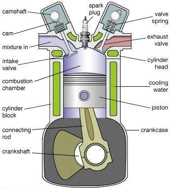
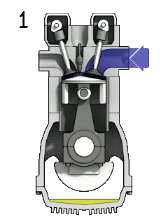
The working cycle of spark-ignition engines may be either two-stroke or four-stroke. A four-stroke spark-ignition engine is an Otto cycle engine. It consists of following four strokes:
- Suction / Intake stroke : Air-fuel mixture enters into the cylinder.
- Compression stroke : Compression of air fuel mixture takes place.
- Expansion / Power stroke : Combustion of Fuel and Power Generation.
- Exhaust stroke : Escaping of burnt gases out of the engine.
Each stroke consists of 180-degree rotation of crankshaft rotation and hence a four-stroke cycle is completed through 720 degrees of crank rotation. Thus, for one complete cycle there is only one power stroke while the crankshaft turns by two or more revolutions.
Application:
- Two stroke SI Engines are used in small vehicles like mopeds and scooters.
- These engines are used for lawn movers.
- These are used in small electricity generating sets and pumping sets.
- Four stroke SI engines are largely used in automobile industries.
- CNG engines are used in buses.
- Radial SI engines are used in small aircraft.
Advantages:
- These engines have lower cost.
- They generate high rpm at low torque.
- It creates less pollution compare to CI engines.
- These engines are light in weight and required less space.
Disadvantages:
- SI engines have low efficiency compared to CI engine.
- These engines are not economical at high load.
- Higher fuel consumption.
- Knocking problem.
PART – 1 : RUN AT 1800 rpm
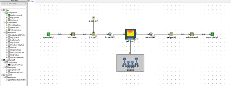
For this case study, we import the inbuilt tutorial model of the SI engine. The model structure of the SI engine is as shown.
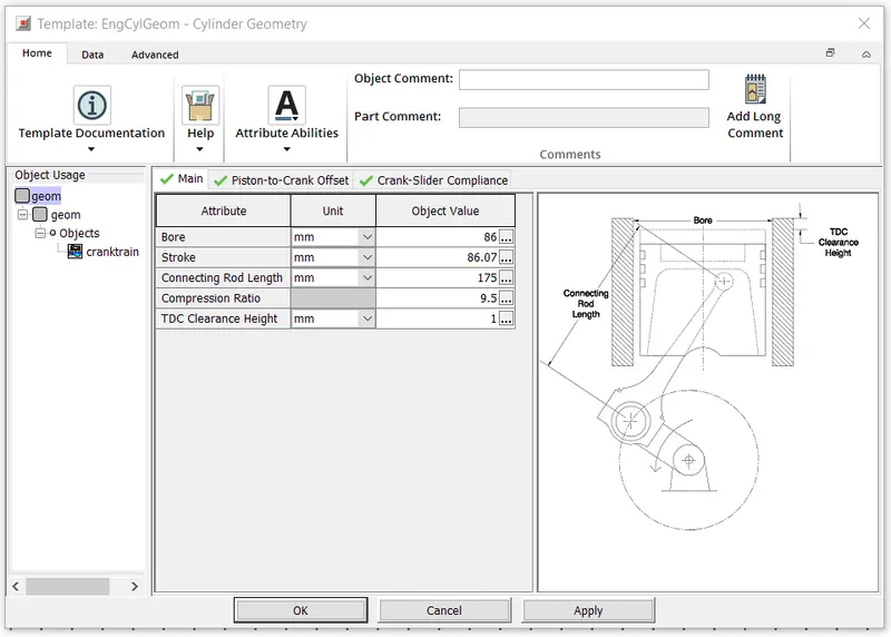
The geometry details of the engine cylinders are as follows.
By setting the engine speed as a parameter, we run the particular case at 1800 rpm by defining the case settings as follows.
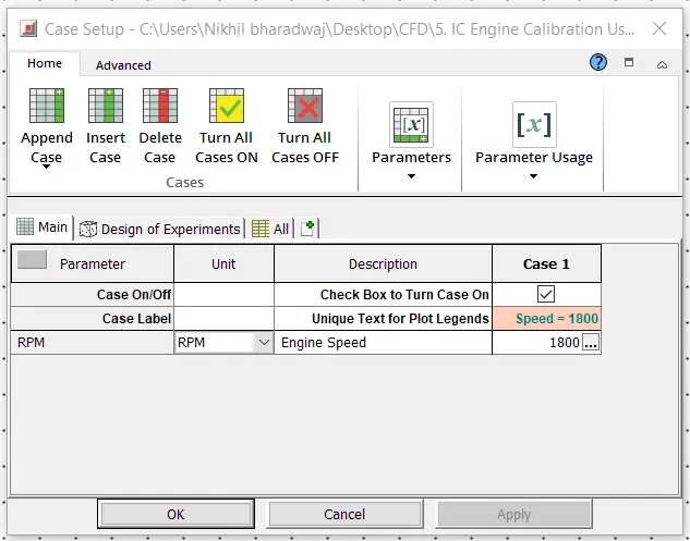
By running the case setup for the above mentioned parameters, we obtain the following simulation results.
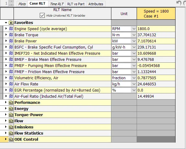
1. Air Flow Rate
Air flow rate in an engine refers to the amount of air entering the engine over a given period of time. By controlling the air flow rate, we can control the rate of combustion and the amount of fuel entering the engine as well. A low amount of air entering the engine leads to incomplete combustion of the fuel and thereby leading to CO emissions, whereas a high amount of airflow into leads to NOx emissions. Therefore, airflow close to stoichiometric ratio is desired.
In this case setup, Air Flow Rate = 24.646 kg/h
2. BMEP
The Brake Mean Effective Pressure (BMEP) is the ratio of work done by the engine during power stroke to the engine displacement. It shows the ability of the engine to generate the maximum brake power based on the engine displacement volume.
`P_(bm) = "Work per power stroke" / V_d`
The brake mean effective pressure is used to compare different engines with varying engine capacity and it is also used to determine how effectively the engine is functioning.
In this case study, BMEP = 9.4767 bar
3. BSFC
Brake-specific fuel consumption (BSFC) is a measure of the fuel efficiency of a combustion engine which burns fuel and produces rotational power. It is the rate of fuel consumption divided by the power produced.
`BSFC = r/P`
Where,
`r` = Fuel consumption rate in grams per second (`g`/`s`)
`P` = Power produced in watts (`W`).
In this case study, BSFC = 239.171 g/kW-h
4. In - Cylinder Pressure
It is the pressure in the engine cylinder during the 4 strokes of engine operation and it is used to estimate the amount of work that can be extracted from the engine.
In this case study, Maximum Cylinder Pressure = 48.891 bar
PART – 2 : INCREASE THE POWER OUTPUT BY 10%
In order to carry out this case study, we first run the simulation for an engine speed of 3600 rpm, in order to obtain the values of power output, which we are going to use as a reference value.
By running the base case setup, we obtain the following output values.
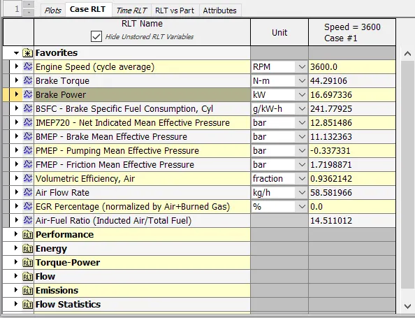
The power output (brake power) value is obtained as 16.69 kW.
We can increase the power output of the engine by one of many techniques.
1. INCREASING COMPRESSION RATIO
In this case study, we setup 3 subcases while maintaining a constant engine speed. The first subcase represents the default compression ratio (9.5). In the next two subcases, we increase the compression ratios to 11 and 13 respectively. The case setup is as follows.
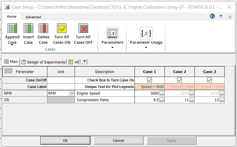
By running the simulation for the above parameters, we obtain our power output figures as follows.
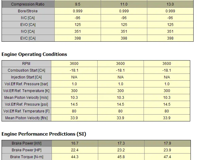
From the above results, we can observe that even when the compression ratio is almost near to the highest value achieved by SI engines, we have not obtained a 10% increase in the power output. Thereby, we move on to try other techniques.
2. VARYING ENGINE GEOMETRY PARAMETERS
In this particular case study, we vary the geometrical parameters of the engine cylinder such as the bore, stroke and connecting rod length. We setup three sub-cases representing the various dimensions of the geometries and we compare the results. The case setup is as shown.
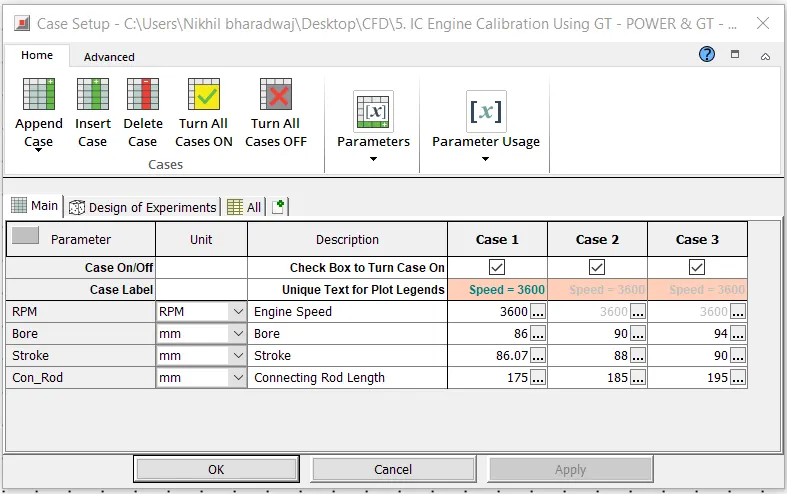
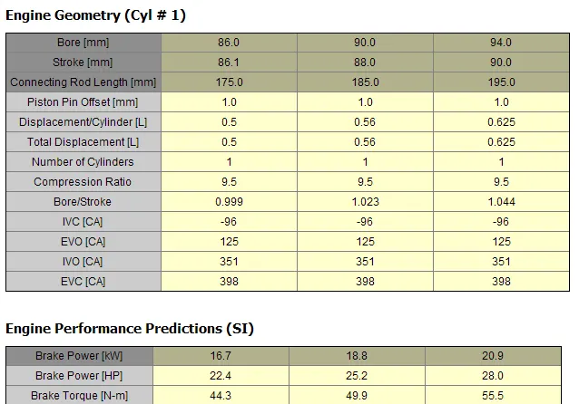
By running the simulation for the above shown parameters, we can observe that the power output has been gradually increased with the increase in the geometrical parameters. Thereby, the required increase in power output has been achieved as follows.
3. INCREASING INLET PRESSURE
In this case study, we increase the inlet pressure of the air entering the engine so as to study its effects on the engine’s power output. A higher intake pressure helps to form a better homogeneous air – fuel mixture and thereby increasing the density of air in the mixture. This increase in intake pressure leads to flame propagation speed increase.
We setup 3 subcases for varying inlet pressures as shown below.
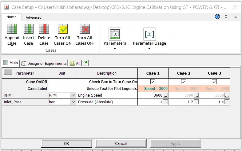
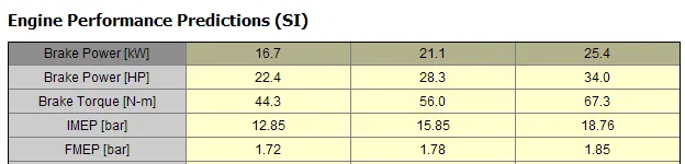
By running the simulation for the above parameters, we obtain our power output figures as shown.

CONCLUSIONS :
A case study of the SI engine running at 1800 rpm has been successfully run and the important parameters have been explained in detail.
By maintaining a constant engine speed of 3600 rpm, we have carried out 3 case studies in which we increase the power output of the engine by varying the engine parameters such as compression ratio, bore, stroke, connecting rod length and the air inlet pressure and thereby obtaining our required increase in power output.