Week 2 : Basic Calibration of Single cylinder SI-Engine
Aim
- To run single cylinder SI Engine simulation setup which is an existing setup at 1800 rpm and list down important parameters such as
- air flow rate
- BMEP
- BSFC
- In-cylinder pressure
- Vary the parameters to increase the power by 30% by running at 3600 rpm
Introduction
Four stroke spark ignition engine working principle.
Four stroke spark ignition engine is given below in 4 steps,
Suction stroke:
Suction stroke starts when piston is at top dead center and about to move downwards. During suction stroke inlet valve is open and exhaust valve is closed. Due to low pressure created by the motion of the piston towards bottom dead center, the charge consisting of fresh air mixed with the fuel is drawn into cylinder. At the end of suction stroke the inlet valve closes.
Compression stroke:
During compression stroke, the compression of charge takes place by return stroke of piston, i.e. when piston moves from BDC to TDC. During this stroke both, inlet and exhaust valve remain closed. Charge which is occupied by the whole cylinder volume is compressed up to the clearance volume. Just before completion of compression stroke, a spark is produced by the spark plug and fuel is ignited. Combustion takes place when the piston is almost at TDC.
Expansion or power stroke:
Piston gets downward thrust by explosion of charge. Due to high pressure of burnt gases, piston moves downwards to the BDC. During expansion stroke both inlet and exhaust valves remains closed. Thus power is obtained by expansion of products of combustion. Therefore it is also called as ‘power stroke’. Both pressure as well as temperature decreases during expansion stroke.
Exhaust stroke:
At the end of expansion stroke the exhaust valve opens, the inlet valve remains closed and the piston moves from BDC to TDC. During exhaust stroke the burnt gases inside the cylinder are expelled out. The exhaust valve closes at the end of the exhaust stroke but still some residual gases remains in cylinder.
Few additional definitions
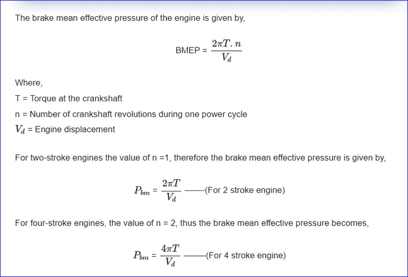
Brake mean effective pressure (BMEP)
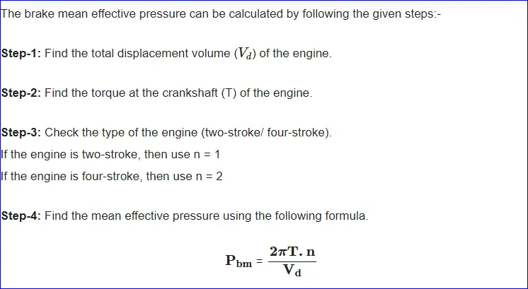
Brake mean effective pressure (BMEP) is an average value of the pressure inside the cylinder and if it is applied uniformly from TDC to BDC instead of the power stroke then the engine will produce the same amount of brake power as an actual engine.
Steps to calculate the BMEP:
Brake specific fuel consumption
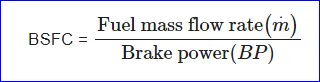
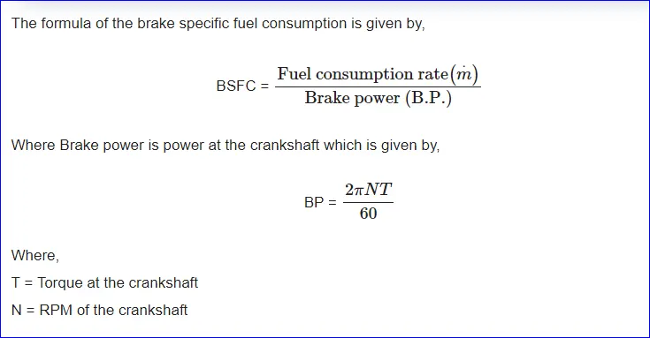
Brake specific fuel consumption is the ratio of a mass flow rate of the fuel supplied to the engine to the brake power obtained at a crankshaft and it indicates how efficiently the fuel is used to produce brake power.
Model and its description:
The model used is 1 cylidner SI engine and its an existing test case in the tutorials. The figure indicating the object
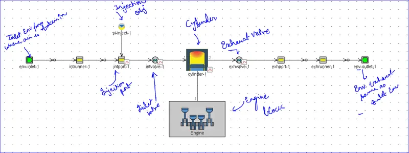
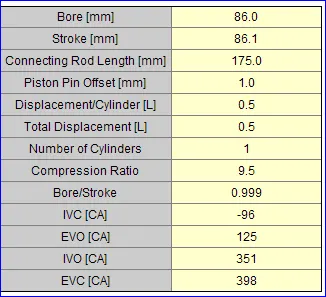
Geometric information:
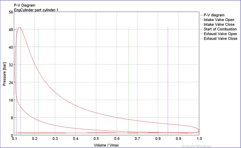
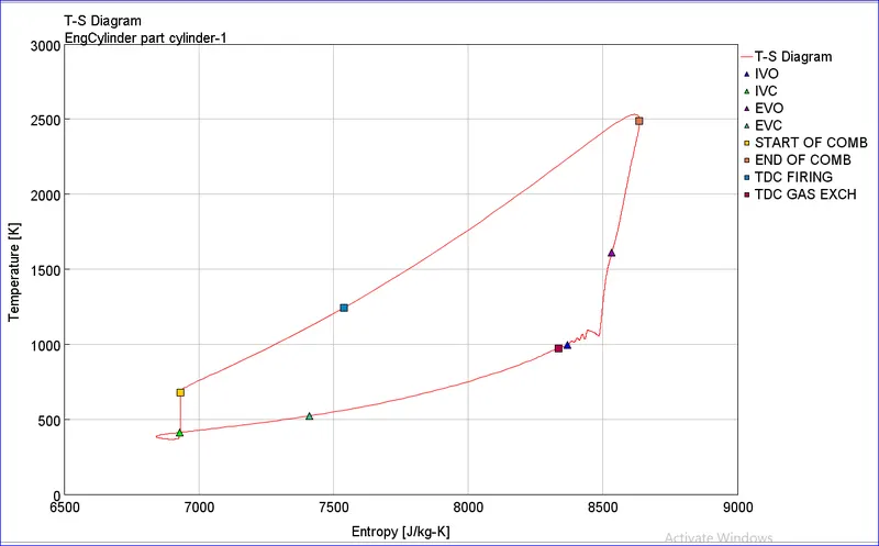
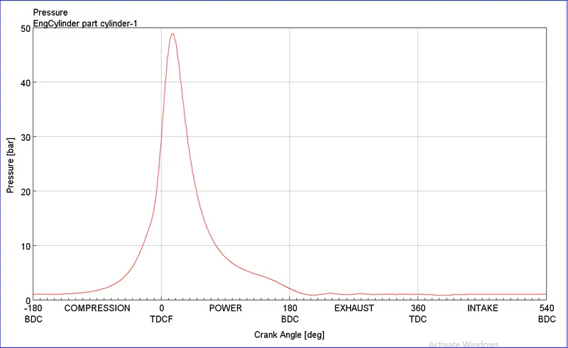
Simulation is run with 1800 rpm and the following are the results:
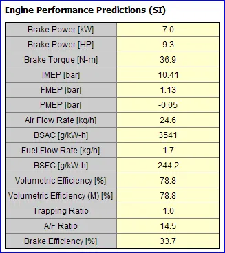
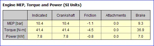
Critical plots at 1800 RPM"
The formula for the power is:
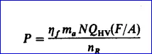
Now in order to increase the performace i.e the power we can increase the rpm, then the volume of the cylinder by changeing the stroke , bore, connecting rod and the inlet pressure.
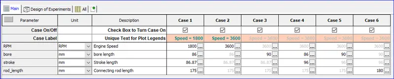
The detailed information on the cases run and the results is shown below in the table:
| Parameters | Case1 | Case 2 | Case3 | Case 4 | Case5 | Case 6 |
| Engine Speed | 1800 | 3600 | 3600 | 3600 | 3600 | 3600 |
| bore length | 86 | 86 | 90 | 86 | 95 | 86 |
| Stroke length | 86.87 | 86.87 | 86.87 | 96 | 80 | 86.67 |
| Connecting rod length | 175 | 175 | 175 | 175 | 180 | 175 |
| Pressure_Env | 1 | 1 | 1 | 1 | 1 | 1.1 |
| Brake Power [kW] | 7 | 16.5 | 18.2 | 18.1 | 18.8 | 16.4 |
| Brake Power [HP] | 9.4 | 22.1 | 24.4 | 24.3 | 25.2 | 22 |
| Brake Torque [N-m] | 37.3 | 43.7 | 48.2 | 48.1 | 49.8 | 43.6 |
| IMEP [bar] | 10.43 | 12.61 | 12.69 | 12.7 | 12.69 | 12.6 |
| FMEP [bar] | 1.14 | 1.73 | 1.73 | 1.85 | 1.65 | 1.73 |
| PMEP [bar] | -0.06 | -0.34 | -0.41 | -0.42 | -0.44 | -0.34 |
| Air Flow Rate [kg/h] | 24.9 | 59.2 | 65.5 | 66.1 | 67.4 | 59 |
| BSAC [g/kW-h] | 3540 | 3594 | 3606 | 3642 | 3590 | 3594 |
| Fuel Flow Rate [kg/h] | 1.7 | 4.1 | 4.5 | 4.6 | 4.6 | 4.1 |
| BSFC [g/kW-h] | 244.2 | 247.7 | 248.5 | 250.9 | 247.4 | 247.6 |
| Volumetric Efficiency [%] | 78.9 | 93.7 | 94.7 | 94.7 | 95 | 93.7 |
| Volumetric Efficiency (M) [%] | 78.9 | 93.7 | 94.7 | 94.7 | 95 | 93.7 |
| Trapping Ratio | 1 | 1 | 1 | 1 | 1 | 1 |
| A/F Ratio | 14.5 | 14.51 | 14.51 | 14.51 | 14.51 | 14.51 |
| Brake Efficiency [%] | 33.7 | 33.3 | 33.1 | 32.8 | 33.3 | 33.3 |
The results and discussions:
- In case 1, the brake power obtained is 7 KW.
- In case 2, the brake power obtained is 16.5 KW.
- In case 3, the brake power obtained is 18.2.kW
- In case 4, the brake power obtained is 18.1 KW.
- In case 5, the brake power obtained is 18.8 KW.
- In case 6, the brake power obtained is 16.4 KW.
We see that:
- Increasing the engine rpm increases the break power of the engine(kepping all other variables constant)
- Keeping engine RPM constant and increasing the volume of the cylinder i.e. bore, stroke connecting rod the break power increases
- For a specific RPM and geometric parameters increasing the Enviroment pressure also increases the break power