Week -2
AIM:
- Make a Simulink model of Doorbell using solenoid block with the given details.
- Use a thermistor to sense the temperature of a heater & turn on or turn off the fan as per given conditions
1.Simulink model of Doorbell using solenoid block:
OBJECTIVES OF THE PROJECT:
- Create a situation where the switch is closed for 2 seconds and then released.
- Observe the physical movement of the plunger.
THEORY:
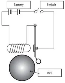
A solenoid is a device comprised of a coil of wire, the housing and a moveable plunger (armature). When an electrical current is introduced, a magnetic field forms around the coil which draws the plunger in. More simply, a solenoid converts electrical energy into mechanical work. In the above arrangement, when the switch is closed the electromagnet receives electrical power from the battery and pulls the metal arm to hit the bell producing sound.
SIMULINK BLOCK DIAGRAM:
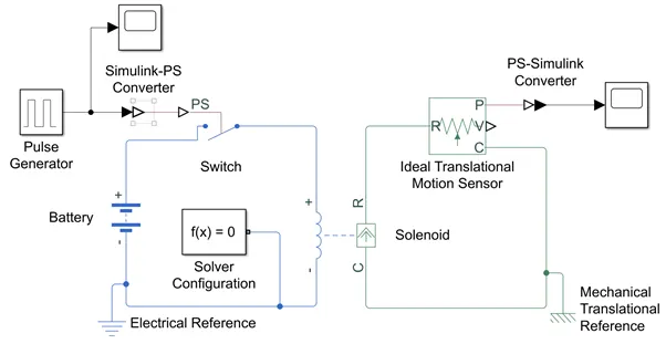
EXPLANATION OF THE BLOCKS:
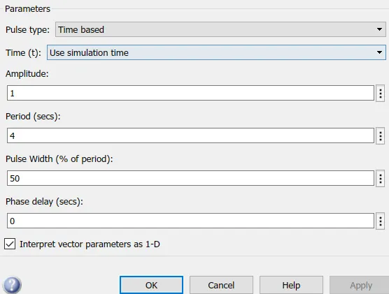
- Initially the parameters set in the Pulse Generator are shown below which is able to generate a ON signal for every 2 second.
- The Pulse Generator is connected to the Simulink System through a Simulink-PS converter which is further connected to a switch.
- The electric component of the Solenoid consists of a the Switch, Battery and Electrical Referrence.
- The Solver Configuration block specifies the solver parameters that your model needs before you can begin simulation.
- The Port C of the Solenoid is connected to the Mechanical Translational Referrence and the Port R is connected to Ideal Translational Motion Sensor to observe the movements of the Plunger.
- The Scope finally shows the output of the movement of the Plunger in the form of vibrations using PS-Simulink converter which converts physical signal to simulink signal.
OUTPUT:
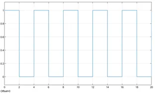
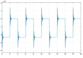
- The below diagram shows the output of the Pulse Generator which becomes ON for every 2 second.
- The below diagram shows the vibrations due to electromagnetic interference during the movement of the Plunger.
CONCLUSION:
Hence the Simulink model of Doorbell using solenoid block with the given objectives is made successfully and the outputs are attached above.
2.Thermistor:
THEORY:
A thermistor is a resistance thermometer, or a resistor whose resistance is dependent on temperature. The term is a combination of “thermal” and “resistor”. It is made of metallic oxides, pressed into a bead, disk, or cylindrical shape and then encapsulated with an impermeable material such as epoxy or glass.
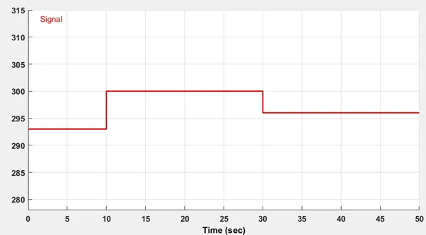
The inputs given in the below simulation are:
- 20 °C from 0 to 10 seconds
- 27 °C from 10 to 30 seconds
- 23 °C from 30 to 50 seconds
Fan conditions: ON if the temperature above 25 °C, OFF otherwise
SIMULINK BLOCK DIAGRAM:
EXPLANATION OF THE BLOCKS:
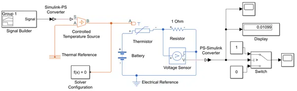
- Initially the signal with the given requirements is provided using the Signal Builder which is connected using Simulink-PS converter.
-
Controlled Temperature source represents an ideal source of thermal energy,that can maintain a controlled temperature difference regardless of the heat flow rate. The temperature difference is set by the physical signal port S. A positive temperature difference causes the temperature at port B to be greater than the temperature at port A.
-
Thermistor is a type resistor whose resistances based upon temperature, which is connected to battery and electrical referrence.
-
A linear resistor of 1 ohm is used is used inorder to control the amount of current from the battery.
-
The voltage sensor is used to convert the voltage measured between two points into a physical signal.
- The voltage is then given to the Switch which compares the value with the given Threshold Voltage. In this case as per the given Switching temperature, i.e., 293K, the Threshold temperature generated is 0.01189V. The switch compares the Threshold value with the input temprature and an output is given to scope.
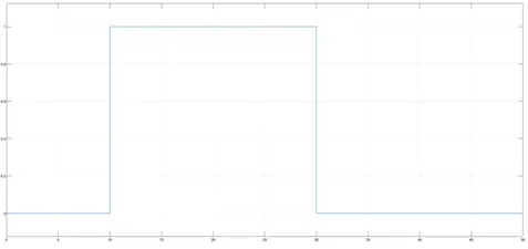
- The output of scope is attached below where only the input voltage value greater than the Threshold Voltage shows an output 1 and the rest 0.
OUTPUT:
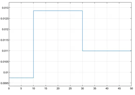
- The voltage sensor value generated for every Signal Builder value is given below:
- The output of the Scope is given below:
CONCLUSION:
The above Simulation was completed successfully and the given conditions are satisfied.