Week -2
PROJECT 1
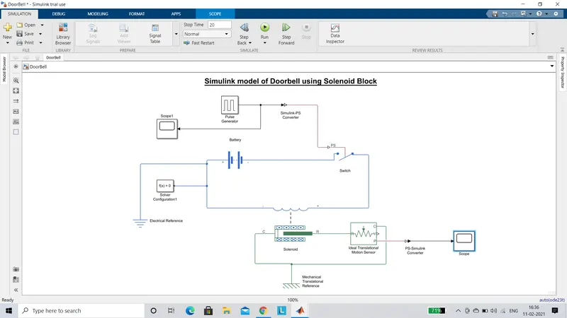
AIM : To make a Simulink model of Doorbell using solenoid block.
SIMULINK BLOCK :
PLOTS :
INPUT PLOT :
OUTPUT PLOT :
EXPLANATION :
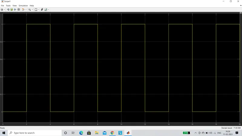
- A Pulse Generator Block is used to create an external physical signal which is used to control the switch.When the external physical signal is greater than the threshold of the Switch Block, the switch is closed, else it is open.A Simulink-PS Converter Block is used to convert the pulse generated by the Pulse Generator to a physical signal which then provided as input to the Switch Block.The output from the Pulse Generator is dispayed using a Scope Block.
- To create a power source a Battery Block is used.Finally a Solenoid Block is used to complete the circuit.
- The electrical circuit is connected to an Electrical Reference Block and a Solver Configuration Block.The Solver Configuration Block is used to define the solver settings required for the simulation process.
- In order to visualize the movement of the plunger in the Solenoid Block, an Ideal Translational Motion Sensor Block is used.The Solenoid Block and the Ideal Translational Motion Sensor Block are connected to Mechanical Reference Block.
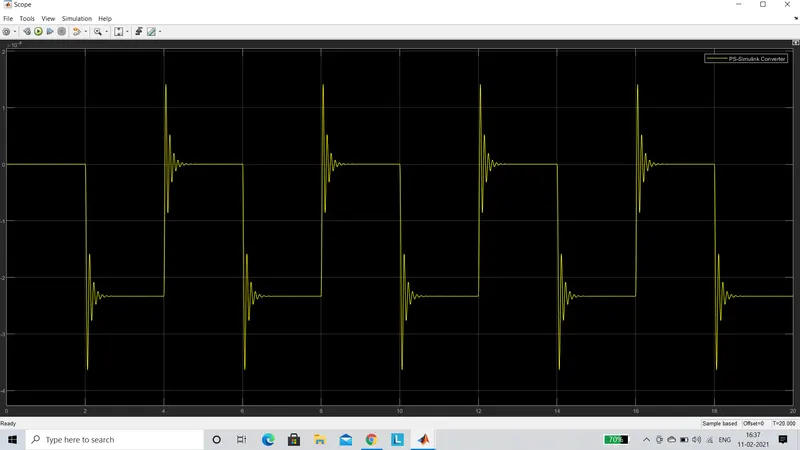
- The P port ie Displacement port from the Ideal Translational Motion Sensor Block is used to display the motion of the plunger by connecting it to a Scope Block.Before connecting it to the Slope Block a PS-Simulink Converter Block is used to provide the input in the ideal form for the Scope Block.
- Thus an output in the form of a plot having a simulation time of 20 seconds is generated with a 2 second interval during each movement of the plunger.
PROJECT 2
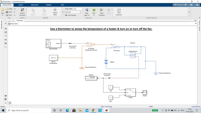
AIM : Use a thermistor to sense the temperature of a heater & turn on or turn off the fan.
SIMULINK BLOCK :
PLOTS :
INPUT PLOT :
OUTPUT PLOT :
EXPLANATION :
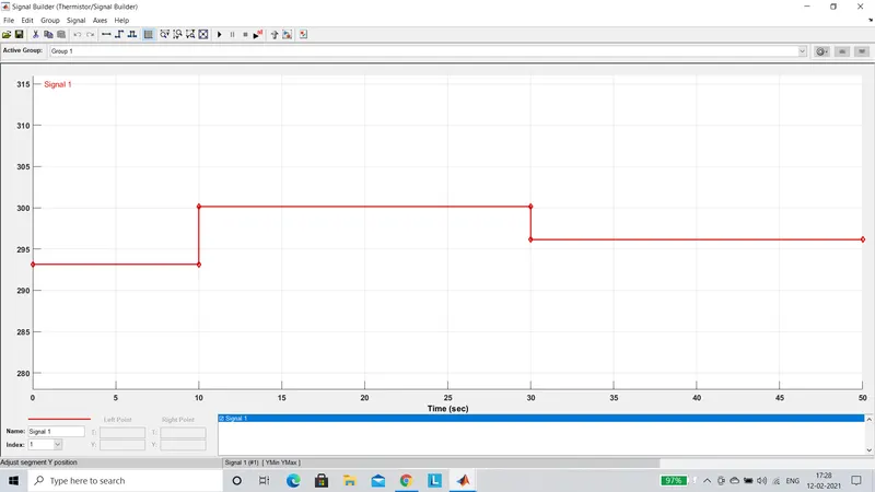
- To provide the input signal to the Controlled Temperature Source Block a Signal Builder Block is used.In the Signal Builder Block the signal is created such that between 0-10 seconds the temperature is 293.15K, between 10-30 seconds the temperature is 300.15K, and between 30-50 seconds the temperature is 296.15K.
- A Simulink PS converter is used to convert the output from the Signal Builder to physical signal, which is the ideal form of input for Signal port (S) of the Controlled Temperature Source.
- The A port of the Controlled Temperature Source is connected to a Solver Configuration Block and a Thermal Reference Block.While the B port is connected to the A port of the Thermistor Block.
- The Thermistor is connected to a Resistor Block and a Battery Block thus forming a circuit.The battery acts as a voltage source while the Resistor is used to monitor the resistance across the Thermistor.
- The resistance between the Resistor is measured in terms of voltage by fixing a Voltage Sensor Block in parallel with the Resistor.
- The output signal from the Voltage Sensor is connected to a Display Block.A PS Simulink converter is used in between the two.
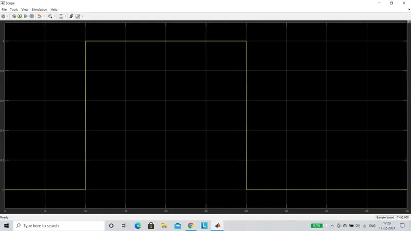
- A Switch Block is used with a threshold of 0.01196 at a temperature of 298.15K.The output from the Volatge Sensor is connected to the input 2 of the Switch Block.While Constant Blocks 1(ON) and 0(OFF) are connected to the input ports 1 and 3 of the Switch Block.When the input to the Switch is greater than threshold the switch is turned ON, else it is turned OFF.
- In order to visualize the Switch position throughout the duration of the Temperature Input Signal a Scope Block is used.