Week -2
AIM:
- To design a Simulink model for the door bell system using solenoid block.
- Design simulink model using a thermistor block to sense temperature of a heater and turn the fan on & off as acoording to the change in the temperature.
ANSWER 1
OBJECTIVE:
- To obtain the required Simulink block model for the given door bell system.
- To make use of the solenoid block from the MATLAB libraries.
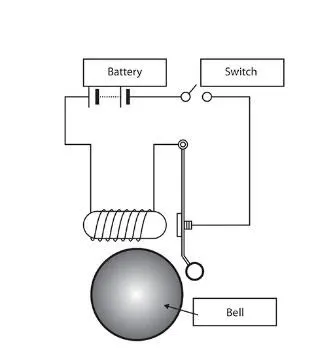
- Observe and recordthe positional behaviour of the plunger in the door bell when the switch is closed for a given instance of time t= 2 seconds .
BODY OF THE CONTENT:
Theory:
The given door bell system works on the basic principle of electromagnetism. It consists of an electromagnet that is excited by a power source when the switch is closed for an interval of time, once it gets excited the magnetic field attracts the iron plunger towards the bell and hits it hence producing a sound.
SOLENOID -
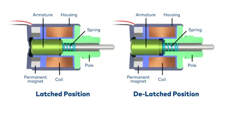
A solenoid is a device comprised of a coil of wire, the housing and a moveable plunger (armature). When an electrical current is introduced, a magnetic field forms around the coil which draws the plunger in. More simply, a solenoid converts electrical energy into mechanical work.
- The coil is made of many turns of tightly wound copper wire. When an electrical current flows through this wire, a strong magnetic field/flux is created.
- The housing, usually made of iron or steel, surrounds the coil concentrating the magnetic field generated by the coil.
- The plunger is attracted to the stop through the concentration of the magnetic field providing the mechanical force to do work.
applications of solenoid:
- Automotive valves, Fuel systems
- power industries,circuit breakers
- fire extinguishers etc.
Now to obtain the Simulink model for this electromagnetic mechanism we make use of the solenoid block that is available to us from the MATLAB libraries.
Following is the procedure to obtain the Simulink model :
- The solenoid block can be used in the model by taking the help of the libraries.
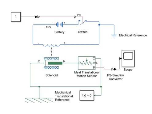
- The electrical circuit of the solenoid having two terminals(+ve and -ve) is powered by a battery block of 12v and the input is controlled by a switch block that is provided by a physical signal PS closed for time t= 2 seconds.
- The physical signal is obtained by converting a constant value provided by the constant block to the Simulink - PS converter.
- Once the coil is excited the mechanical part is either attracted or repelled (i.e R moves toward C or R moves away from C.)
- The plunger moves and the mechanical arm hits the bell for the switching time period.
- The physical movement of the plunger can be analysed using the translational motion sensor.
- Port R of the plunger is connected to port R of the sensor, the sensor output port P gives the displacement of the plunger.
- The physical displacement output from the sensor is converted to Simulink output using the PS-Simulink converter.
- The physical displacement of the plunger can be observed in the graph obtained using the scope block.
SIMULINK MODEL:
RESULT:
Plot for the displacement of the plunger with respect to time.
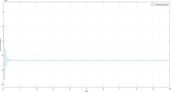
- The displacement of the bell plunger can be seen in the above plot when the switch is closed for a time t=20s
- A small physical movement can be observed which later diminishes after an a certain time.
CONCLUSION: The simulink model for the design of a door bell is obtained with the help of the solenoid block from the MATLAB libraries and analysed the working of the door bell based on the principle of solenoid practically.
2)https://www.youtube.com/watch?v=Sq-CYfp9t4c&feature=emb_title
3)https://passive-components.eu/solenoids-contactors-and-electromechanical-relays-explained/
ANSWER 2
OBJECTIVE:
- To design a Simulink model of a thermistor model to sense a temperature of the heater and then turn the cooling fan/off.
- To make use of the pre designed thermistor block from the MATLAB libraries.
Given conditions:
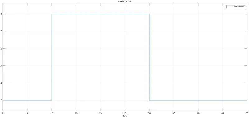
Temperature: 20 °C from 0 to 10 seconds, 27 °C from 10 to 30 seconds, 23 °C from 30 to 50 seconds
Fan conditions: ON if the temperature above 25 °C, OFF otherwise
BODY OF CONTENT:
THEORY:
THERMISTOR- It is a type of resistor whose resistance varies with changes in temperature.he temperature measured from this thermistor produces accurate values. These are of cheap and robust nature. But it doesn’t go well when we connect it in extreme cold and hot conditions. When the requirement is raised to maintain certain limited range thermistors are preferred. In the case of large temperature range RTDs are used because they are made up of pure metals.
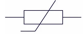
Thermistor- symbol
Thermistors functioning is described as
- The principle obeyed by the thermistor is its dependency on-resistance values on the change in temperature.
- The value of resistance can be measured by using an ohmmeter. These are connected in series with the battery and the meter.
- The change in the resistance is depending upon the material chosen in the construction of the thermistor.
- Thermistors are considered to be a special variety of resistors. Generally, the resistor is known for limiting the amount of current in the circuit.
- But in this thermal resistors, the change in the resistance is dependent upon the change in temperature.
- If the temperature tends to increase the resistance in the circuit decreases in these special variants of resistors. It is decided based on the coefficient of temperature.
The applications of thermistors are as follows:
- These are compact. It can be used as a temperature sensor in Digital Thermometers.
- In the automotive industry to measure the temperature of the coolant and the oil in the trucks as well as in cars these are preferred.
- Household appliances make use of thermistor to increase or decrease the amount of heat required.
Procedure to design Simulink model:
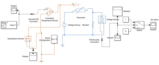
- At first we make use of the signal build block to obtain the varying temperature signal to be provided as an input to the thermistor.
- The temperature signal is converted to a physical signal using Simulink-PS converter.
- The physical signal is provided to a controlled temperature source at port S and Port A is provided to a reference temperature. A positive temperature difference between S and A causes a positive temperature at B.Temperature at B can be sensed by a temperature sensor.
- The output temperature is now provided to the thermistor at the heat port A. The electric circuit of the thermistor consists of a 12V DC Voltage source and a voltage sensor connected to an external resistance .
- The voltage sensor senses the voltage across the thermistor and converts it into a physical signal at pot V.
- The physical signal is converted back into Simulink signal which is compared with the threshold voltage at input 2 of the switch
- The switch will pass through input 1 if the voltage at input 2 of switch exceeds the threshold or passes through input 2 if it doesn’t exceed.
- Threshold voltage for the switch is set at12.8 mV.
- The switch is configured such that it returns a value (1) when it passes input1 thereby turning On the fan or returns a value (0) when it passes input 2 which turns off the fan.
SIMULINK MODEL:
RESULTS:
INPUT SIGNAL
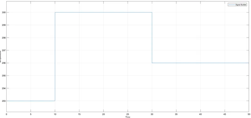
For time: t=0 - 10 seconds,temperature T=293K.(20deg C)
time: t=10 - 30 seconds,temperature T=300K.(27deg C)
time: t=30-50 seconds,temperature T=296K
VOLTAGE SENSOR OUTPUT
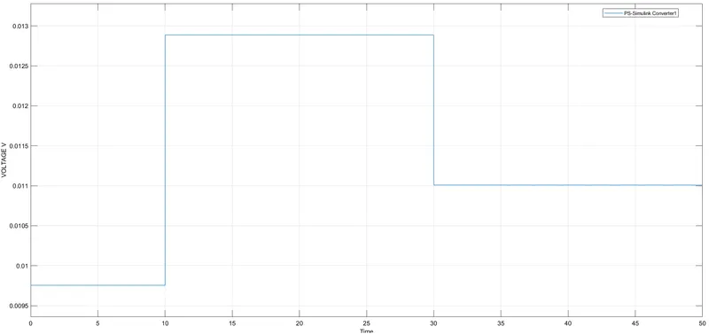
VOLTAGE: 9.755 mV for t= 0 to 10s at T=293K
12.8 mV for t=10 to 30s at T=300K
11mV for t=30 to 50s at T= 296K
FAN STATUS
CONCLUSION:
The simulink model for the design of a temeperature sensing device is obtained with the help of the thermistor block from the MATLAB libraries and analysed its working based on the principle of thermistor practically.
REFERENCES: