Week - 4
AIM:
- To Implement control logic of a “washing machine” using Stateflow.
- To Make a Simulink chart for the “Gear shift” logic.
OBJECTIVE:
To obtain the stateflow model for the washing machine as per the given sequence:
- If the power supply is available, the system gets activated
- If the Water supply is not available, stop the process & indicate through LED
- Soaking time should be 200s followed by Washing time of 100s.
- Then rinsing happens for next 20s & dryer runs for 50s.
After all the processes have completed turn on the finished LED.
To obtain a simulink chart for a gear shift logic using the given conditions:
Speed Range(kmph) Gear
0 to 15 1
16 to 25 2
26 to 40 3
41 to 60 4
Above 61 5
Give speed input while the simulation is running & display the gear number.
PROCEDURE:
WASHING MACHINE CONTROL LOGIC:
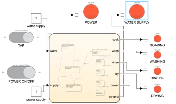
- Two inputs are required to be provided, one for the power supply and other for the water supply.
- The logic is modelled in such manner that the washing machine performs it’s complete cycle only when both the power and water supply are available else it remains standby.
- Both inputs are provide with two constant blocks that are in turn connected with slider switches respesctively.
- At position 1 the slider switch is on and at position 0 the slider switch is off.
- Each mode of operation or states of the machine are enclosed within the stateflow chart.
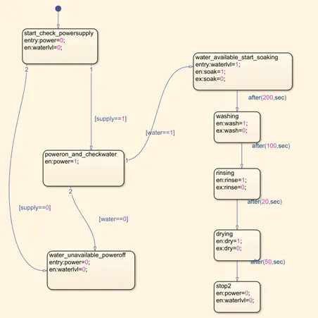
- In the first state the power supply is checked and a transition to next state occurs when power supply is either equal to 0 or 1. If supply=0 the machine turns off.
- Water supply availability is ensured in the next state. if water is available the transition continues to next state else if unavailable the machine power is turned off.
- The next set of operations are carried out based on the time delay given between each states.
- The output for all states namely soak,wash,rinse and dry are set as 1 at entry and exit and for the termination state output is set as O at entry at exit.
- Transition statement between each states represents the time for which each operation is performed. The time values given are soak:200s, wash:100s, rinse:20s, dry:50s post which the cycle ends.
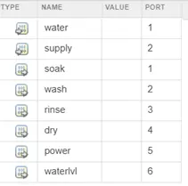
- The input and output for the stateflow is defined in symbol pane after making the blocks and defining transition statements as defined below:
12. LEDs are used to indicate the power supply, water supply, and each state of cycle. Total run time = 370s for whole washing machine operation cycle.
STATEFLOW [CHART]:
.
.
.
GEAR SHIFT CONTROL LOGIC:
SIMULINK BLOCK DIAGRAM:
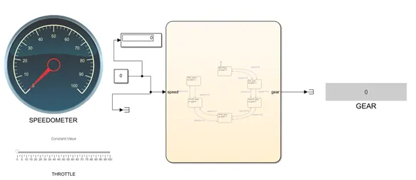
- The speed is the input given to the chart using the slider to give different speed acting as a throttle.
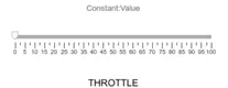
- A constant block is fed to input values of which are changed during run using the slider and time is set as inf. The input value is changed using a slider with parameters set as below:
- The input is also connected to a gauge to show the speed as slider is varied during run time.
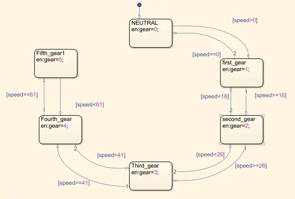
- Each states inside chart are named as first, second and on till fifth gear.
- Since the output to be displayed is gear position as speed changes the output statements inside all block from gear 1 to gear 5 .
- The transition occurs to different speeds for which a gear is shifted from one to another. The transition statements are based on speed range which is set as input. The transition statements are shown below:
Speed Range (kmph) Gear transition
0 to 15 shift to 1st gear
16 to 25 shift to 2nd gear
26 to 40 shift to 3rd gear
41 to 60 shift to 4th gear
Above 61 shift to 5th gear
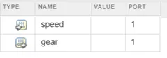
- The variables are defined in symbol pane as below:
STATEFLOW [CHART]:
CONCLUSION:
The control logics of both systems can be obtained using the state diagram which is a form of hierarchical state machine.
Thus the Stateflow helps in providing a graphical representation that includes state transition diagrams, flow charts, state transition . Hence, we can use it to analyse any kind of real world system operation.