Design of Doorbell and Control of Fan
Aim:
1) Make a model of a Doorbell using solenoid block with the following details:
- When the switch is closed, the electromagnet should receive electrical power from the battery and pull the metal arm to hit the bell producing sound.
- Create a situation where the switch is closed for 2 seconds and then released.
2) Use a thermistor to sense the temperature of a heater & turn on or turn off the fan as per the below conditions:
- Temperature source: 20°C from 0 to 10 seconds, 27°C from 10 to 30 seconds, 23°C from 30 to 50 seconds.
- Fan conditions: ON if the temperature above 25 °C, OFF otherwise
Software Used: Simulink
Modeling of a Doorbell using Solenoid Block:
Block Diagram:
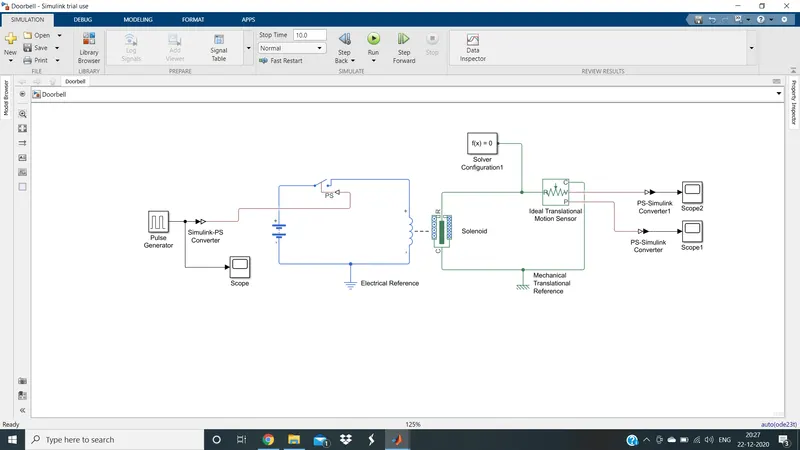
Theory:
- Solenoid: A solenoid is a device comprised of a coil of wire, housing, and a moveable plunger (armature). When an electrical current is introduced, a magnetic field forms around the coil which draws the plunger in. More simply, a solenoid converts electrical energy into mechanical work.
- First, we have the pulse generator which generates the desired pulses. Make sure that in the pulse generator, the period is 4 seconds and phase delay is set as 2 seconds i.e. according to the aim. This Simulink signal is sent to a physical switch via a Simulink-PS Converter. This makes sure that the switch is closed for 2 seconds and then released for 2 seconds and the process is continued. This switch is then connected to a solenoid along with a battery as shown in the figure above.
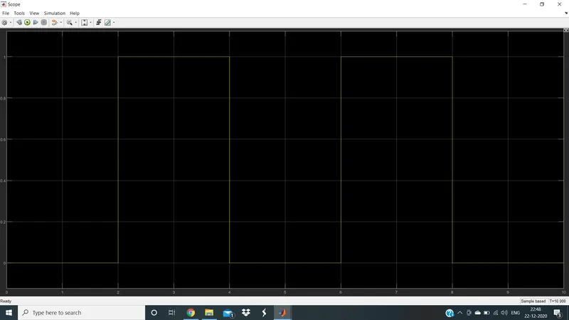
- In a doorbell, the solenoid motion is in the downward direction. Hence, in solenoid block parameters, set motion direction under excitation as port R moves away from port C.
- Then, this solenoid is connected to an ideal translational motion sensor to sense the output signals. After this, join the common terminal of an ideal translational motion sensor and the solenoid.
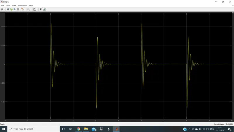
- The ideal translational motion sensor is connected to scope 1 and scope 2 via PS-Simulink converters in order to obtain the position vs time and velocity vs time plots respectively.
- Finally, connect the references and solver configuration and run the program with a stop time of say 10 seconds.
Outputs:
Position (Y-Axis) vs Time (X-Axis) From Scope 1
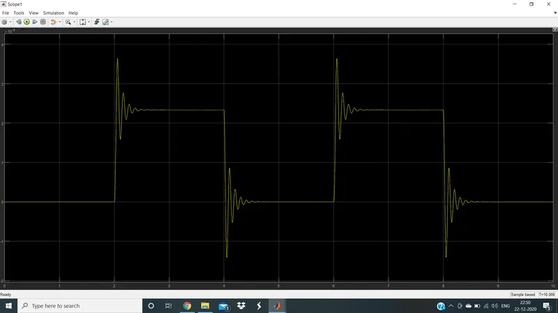
Velocity (Y-Axis) vs Time (X-Axis) from Scope 2
Modeling a thermistor to sense the temperature of a heater & turn on or turn off the fan:
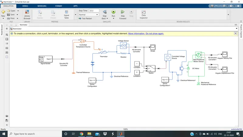
Block Diagram:
Theory:
- The signal builder is used to create and generate interchangeable groups of signals whose waveforms are piecewise linear. It helps us generate an input waveform as mentioned in the aim.
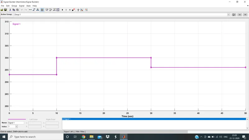
- This input signal is then sent to a controlled temperature source via Simulink-PS converter. In the converter, make sure that the first-order filtering is enabled since the input is continuous.
- The Controlled Temperature Source block represents an ideal source of thermal energy that is powerful enough to maintain specified temperature difference across the source regardless of the heat flow consumed by the system.
- The output is of the controlled temperature source is given to the thermistor. A thermistor is a resistance thermometer or a resistor whose resistance is dependent on temperature. The Thermistor block represents a negative temperature coefficient thermistor using the B-parameter equation. The resistance at temperature T is given as R=R0eB(1/T−1/T0).
- The thermistor receives power from a battery and a voltmeter is connected across the resistor in the circuit to record voltages at different temperatures.
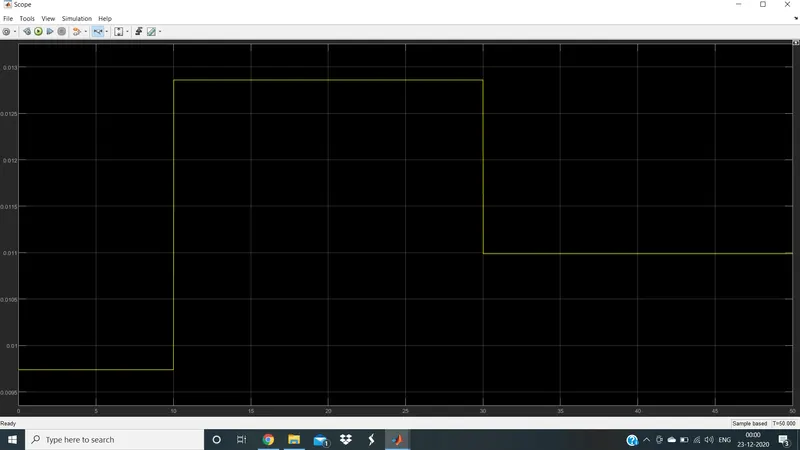
- From the scope connected to the voltmeter via PS-Simulink converter, we can find out at what voltage the temperature is exceeding 25 degrees centigrade (298 Kelvin). And with that knowledge, we have programmed the switch to turn on when the temperature exceeds 25 degrees centigrade and turn off otherwise.
- It was known that above 0.011v the temperature exceeds 25 degrees centigrade.
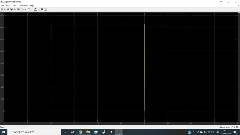
- Then we convert the output of the switch to a physical signal and transfer the signal to a dc motor via a controlled voltage source. Then, the output of the dc motor is sensed by the ideal rotational motion sensor.
- Finally, the sensed outputs are converted to simulink type via the converters, and plots are obtained via scopes.
- Please remember to connect the circuit to solvers and references as shown above. Also, make sure that the simulation time is set as 50 seconds which is in accordance with our aim.
Outputs:
Voltage (Y-Axis) vs Time (X-Axis) from Scope
Angular Velocity (Y-Axis) vs Time (X-Axis)
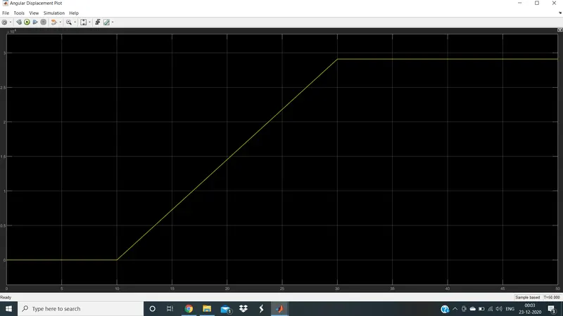
Angular Displacement (Y-Axis) vs Time (X-Axis)