Week -2
Question 1: Make a Simulink model of Doorbell using solenoid block with the following details:
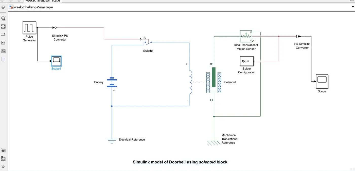
Step 1: We create input to the solenoid by using Simulink PULSE block by connecting it to SWITCH block (Simscape) via 'Simulink to PS convertor'.
Step 2: We generate SOLENOID block and connect its spring end to DC Battery source , which is further connected to reference 'Electrical Reference' block.
Step 3: The Plunger end of SOLENOID block is connected to Idela Translation Motion sensor ,and its is further connected to Mechanical Translation Reference block.
Step 4:The Physical Simscape system is then connected to SCOPE block using Physical to Simulink convertor.
Step 5: Overall Physical model is connected to 'Solver Configuration' block to run the simulation.
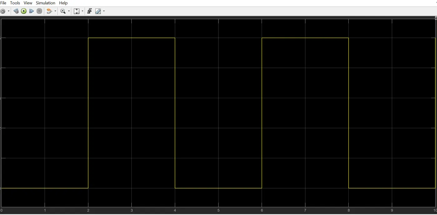
Step 6: Input is provided to the SOLENOID using SCOPE block, which uses Pulse as input form. Phase delay of 2 seconds is applied to it which cuts the input pulse source after 2 seconds. Due to which switch get turned off after every 2 seconds and there is a change in magnetic flux (electromagnetic effect) in SOLENOID , which produces the translation movement of plunger(bell door arm).
The Input signal characteristics is as follows:
Final MODEL:
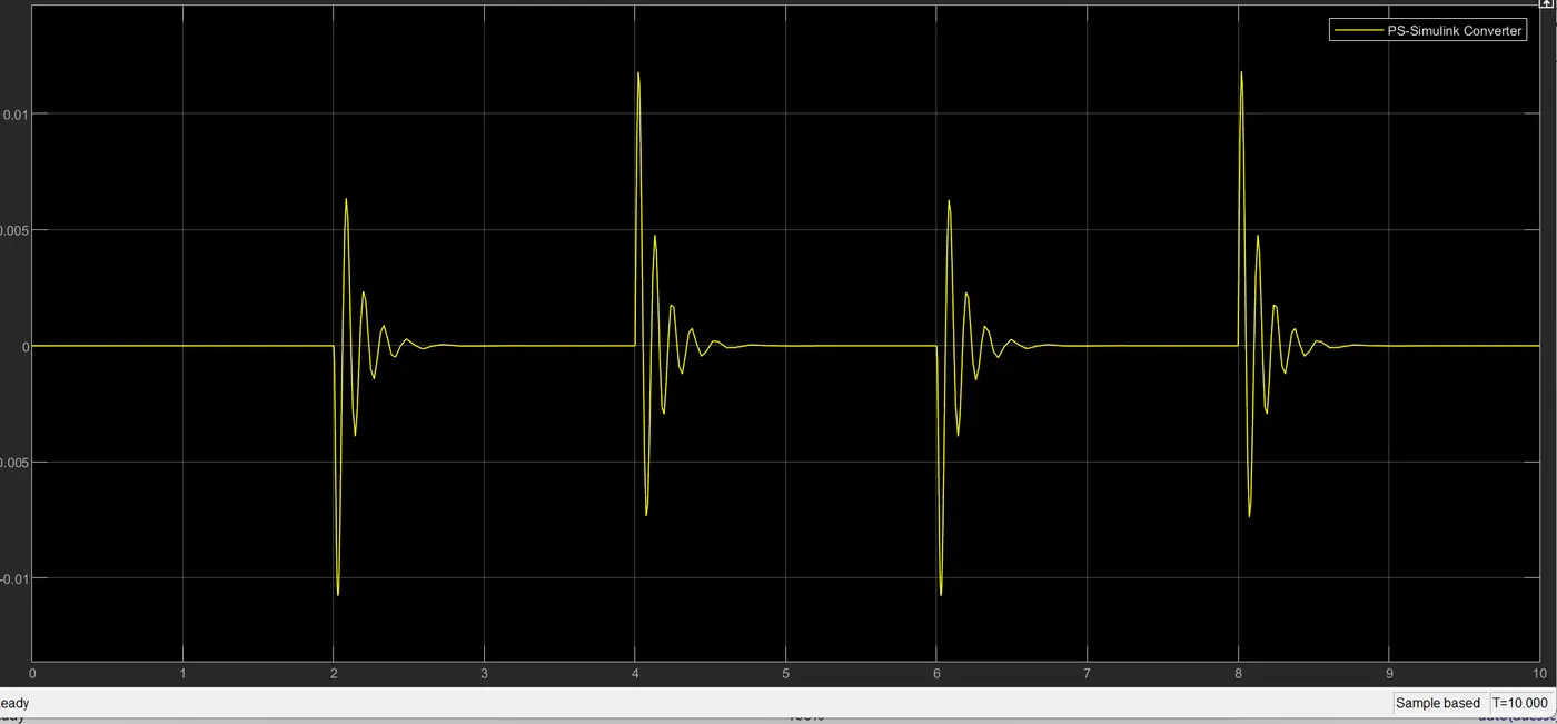
Result:
We run the simulation and get the movement of metal arm that hits the bell producing sound. The output of the metal arm movement is recorded in SCOPE block as follows:
Google drive link of Solenoid model:
https://drive.google.com/file/d/16bRu9n3qrUiUV3HJ5ywsBeJ5vnaStHVY/view?usp=drive_link
Question 2: Use a thermistor to sense the temperature of a heater & turn on or turn off the fan as per the below conditions
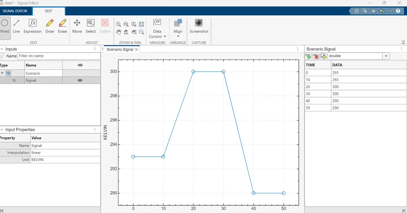
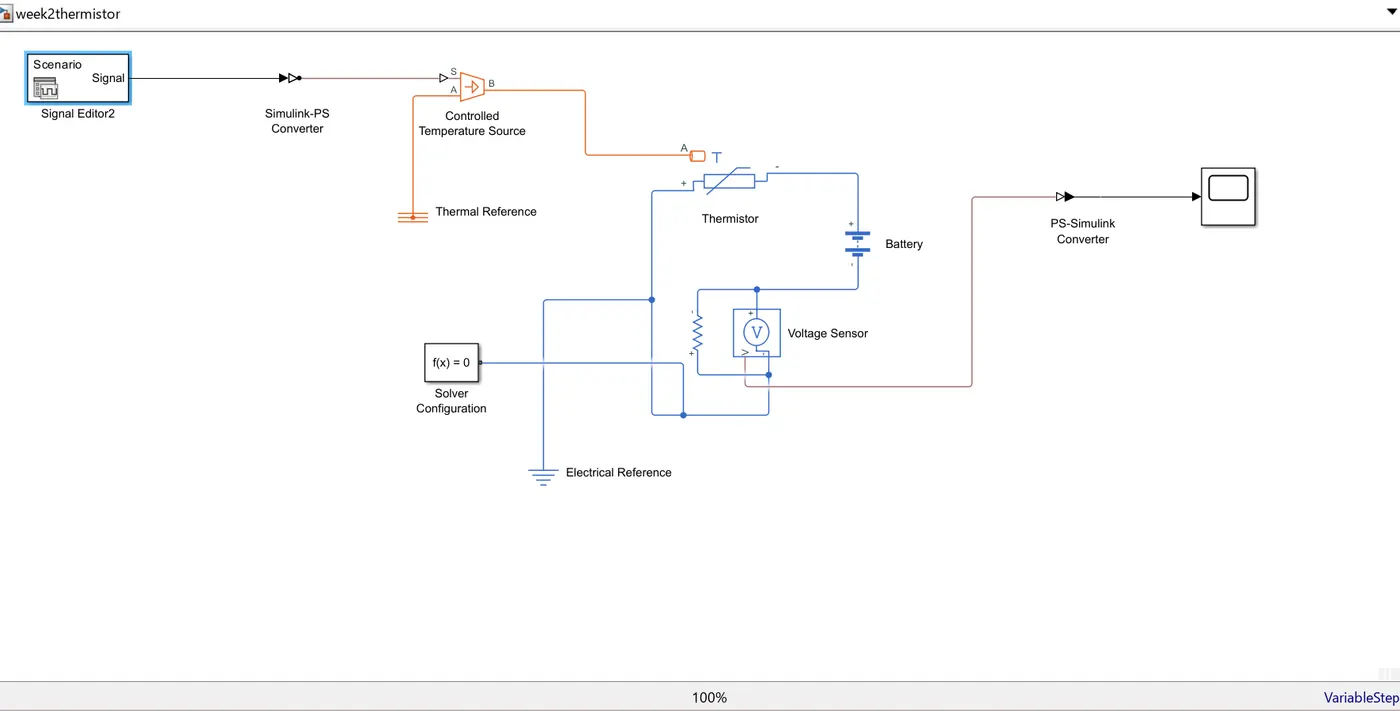
Step 1: Give the temperature input to the Controlled Temperature source via Signal Editor block with help of Simulink to Physical convertor. Thermal Reference' block must be connected to the Controlled Temperature source block.
The varying input signal is provided as follows to the Thermistor:
Step 2: We connect this source to the thermistor which is connected to a DC battery source, resistor and voltage sensor. This Thermistor physical model is connected to a 'Electrical Reference' block.
Step 3: The output of voltage sensor is connected to SCOPE block to view the results of change in temperature which varies the output voltage of the Thermistor.
Step 4: Now we connect the model to a Solver configuration block to run the simulation.
Google drive link of Thermistor model:
https://drive.google.com/file/d/11_rCziXUqxU-Ju3j_9iyEqICvupRGltw/view?usp=drive_link