Project 1
1.
Given:
Voltage of battery pack=120V
Energy of battery pack=150KWh
Voltage of single cell=3.6V
Capacity of each cell=3500mAh=3.5Ah
Now,
Capacity of battery pack=Energy of battery pack/Voltage of battery pack
Capacity of battery pack=150KWh/120V
Capacity of battery pack=150*103Wh/120V
Capacity of battery pack=1250Ah
Now,
Number of cells in parallel=Capacity of battery pack/Capacity of each cell
Number of cells in parallel=1250Ah/3.5Ah
Number of cells in parallel=357.14=358 Cells
Now,
Number of cells in series=Voltage of battery pack/Voltage of single cell
Number of cells in series=120V/3.6V
Number of cells in series=33.33=34 Cells
While designing a battery pack topology/configuration we consider the cells in series as cells in parallel have same voltage across them.
Centralized Topology allows a maximum of 18 cells so we can not go by this topology.
Distributed topology is used for smaller battery packs.
While Modular topology involved high cost , so we will proceed with Master slave technology.
Diagram of the required battery pack topology is as follows:
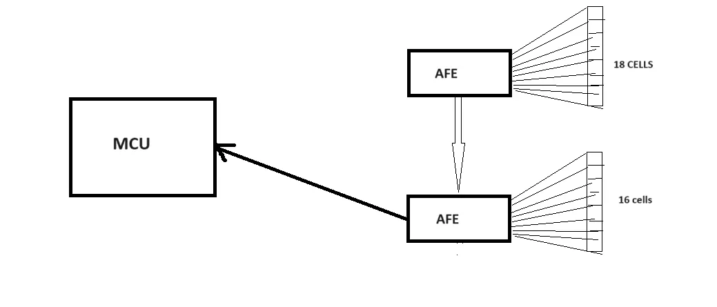
Description: In a battery management system (BMS), a master-slave topology refers to the hierarchical arrangement of components within the system. This architecture is designed to efficiently manage and monitor the performance of individual battery cells or modules within a larger battery pack.
At the heart of the master-slave topology is the master controller(MCU-Microcontroller), which serves as the central hub for communication and control. The master controller is typically a powerful microcontroller or processor capable of handling complex tasks such as data processing, decision-making, and system coordination. It acts as the brain of the BMS, orchestrating the operation of the entire system.
Connected to the master controller are multiple slave devices(AFE-Analog Front end), each responsible for monitoring and controlling specific aspects of the battery pack. These slave devices can include cell voltage monitoring circuits, temperature sensors, current sensors, and balancing circuits. By distributing the workload among multiple slaves, the BMS can effectively manage a large number of battery cells or modules with high precision and efficiency.
AFE converts the analog signal (like cell voltage, temperature)to digital form.
One of the key advantages of the master-slave topology is its scalability and flexibility. The system can easily accommodate changes in the number of battery cells or modules by adding or removing slave devices as needed. Additionally, the modular design allows for easier troubleshooting and maintenance, as individual slave devices can be replaced without affecting the overall functionality of the BMS.
Overall, the master-slave topology in a battery management system provides a robust framework for efficiently monitoring, controlling, and protecting battery packs in various applications ranging from electric vehicles and renewable energy systems to portable electronics and grid-scale energy storage
2.
AIM: To build a 3S2P battery pack configuration with generic battery block using Matlab/Simulink.
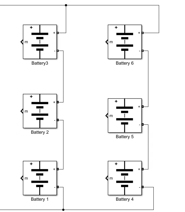
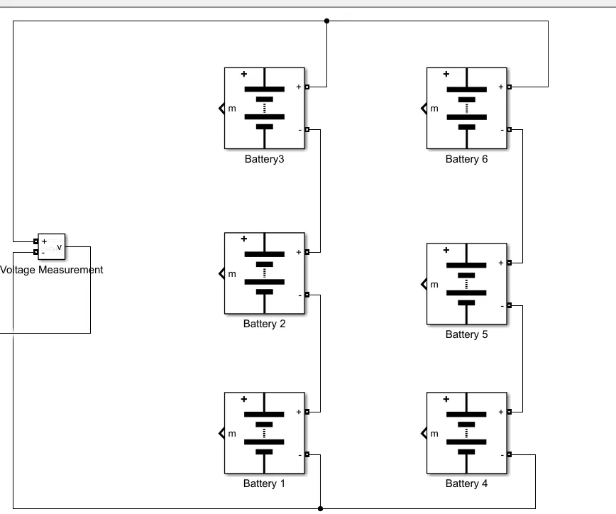
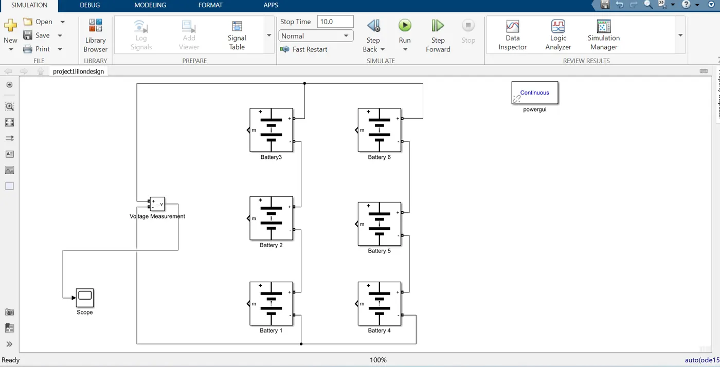
STEP 1 (Design): We add six 'Battery' mask blocks (two sets of 3 each) in the Simulink and connect the positive terminal of first battery to negative terminal of second battery and positive of second battery to negative terminal of third battery . Similarly, we connect the second set of three batteries in series connection. Now, the negative terminal of first battery and fourth battery are connected to a common bus junction and positive terminal of third battery and sixth battery from both sets are connected to a common bus junction to create a parallel connection between two sets . This arrangement results in design of a 3S2P battery pack configuration.
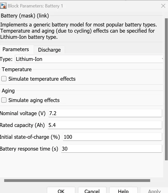
The properties of each battery block are as follows:
Each battery has a default nominal voltage of 7.2 Volts,
STEP 2: Now we add 'Voltage Measurement' block to the model and connect it to the respective overall positive and negative terminals of battery pack.
STEP 3: Now we add the 'Voltage Measurement' block to a 'Scope' block to view the overall voltage of the 3S2P battery pack. We run the simulation for the battery pack model and observe the scope block results. Further we add a 'powergui' solver block to the Simulink model to run the complex circuit connection model.
Step 5:
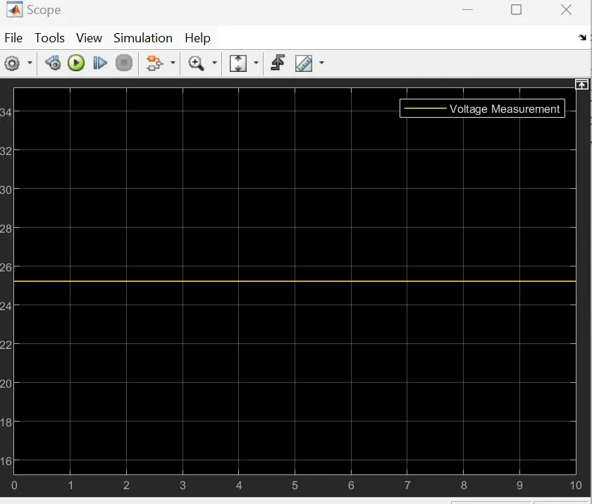
The output of the scope showcases the resultant voltage of the 3S2P battery pack configuration.