CREATING A SIMULINK MODEL OF A DOORBELL AND A HEATER SATISFYING THE REQUIRED CONDITIONS
AIM -
1. To make a Simulink model of doorbell using a solenoid block and create a situation where the switch is closed for 2 seconds and then released using which we observe the physical movement of the plunger.
2. To create a Simulink model of a thermistor to sense the temperature of a heater and turn the fan off or on as per the given conditions.
AIM 1 -
1. To make a Simulink model of doorbell using a solenoid block and create a situation where the switch is closed for 2 seconds and then released using which we observe the physical movement of the plunger.
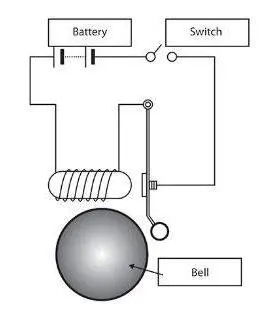
In the above arrangement, when the switch is closed the electromagnet receives electrical power from the battery and pulls the metal arm to hit the bell producing sound. We need to create a situation where the switch is closed for 2 seconds and then released and observe the physical movement of the plunger.
THEORY -
Before creating the Simulink model of the electric bell, let us learn the basics behind the same.
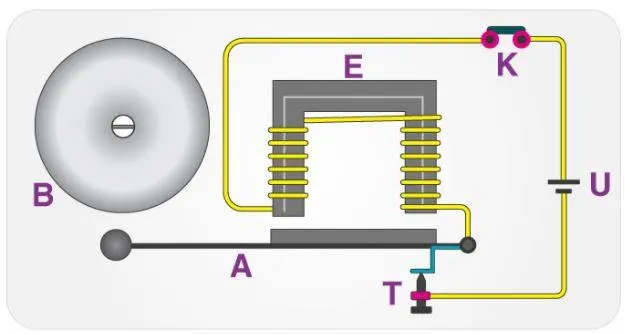
The electric doorbell is a simple circuit that triggers a sound on the completion of the circuit by pressing the button. It is this simplicity that makes the doorbell such a marvel. The simple devices in the doorbell put the scientific principle of electromagnetism into action in a useful way. An electromagnet is basically a type of magnet in which the magnetic field is produced with the help of an electric current. When any electrical influences electromagnet it works as a standard magnet (generating magnetic fields). When the power generation to an electromagnet stops, the production of the magnetic field also stops. So, in an electric bell, an electromagnet forms an important part along with Armature, Spring, Armature rod, Hammer, and a Gong. An electric source, for example, a battery can be used to power the electromagnet used in an electric bell. The electric circuit is completed by installing a push switch which you can press to generate sound in an electric bell. The switch also acts as the circuit breaker.
So once the setup is completed, when the switch is pressed, the circuit loop is complete which causes the current to flow through the circuit. The arm which strikes the gong is connected to a spring at one end and an iron ball at the other end. This is called a hammer or a striker. The arm is attached to an iron strip which is attracted to the electromagnet when the circuit is complete and the current flowing through it. It’s mainly because the magnetic field created by the electromagnet attracts the iron strip towards it when the circuit is complete. This is the moment when you hear the ringing sound since the hammer keeps hitting the gong. Meanwhile, at its rest position, the hammer is held away from the gong on account of the spring attached to its arm. This is an anchored arm.
For the electromagnet, we will be using a solenoid in our setup of the electric doorbell. The theory regarding a solenoid is briefly explained below.
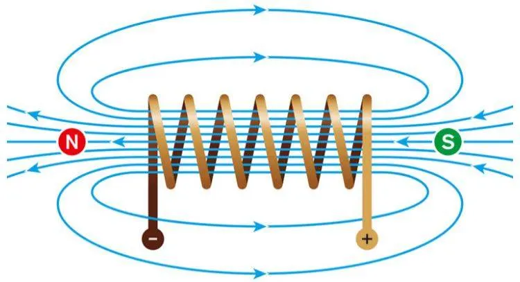
A solenoid is a long piece of wire which is wound in the shape of a coil. When the electric current passes through the coil it creates a relatively uniform magnetic field inside the coil. The solenoid can create a magnetic field from an electric current and this magnetic field can be used to generate a linear motion with the help of a metal core. This simple device can be used as an electromagnet, as an inductor, or as a miniature wireless receiving antenna in a circuit.
The solenoid simply works on the principle of “electromagnetism”. When the current flow through the coil magnetic field is generated in it, if you place a metal core inside the coil the magnetic lines of flux are concentrated on the core which increases the induction of the coil as compared to the air core. Most of the flux is concentrated only on the core, while some of the flux appears at the ends of the coil and a small amount of flux appears outside the coil. The magnetic strength of the solenoid can be increased by increasing the density of the turns or by increasing the current flow in the coil. Like all other magnets, the activated solenoid has both Positive and Negative poles, through which an object can be attracted or repelled.
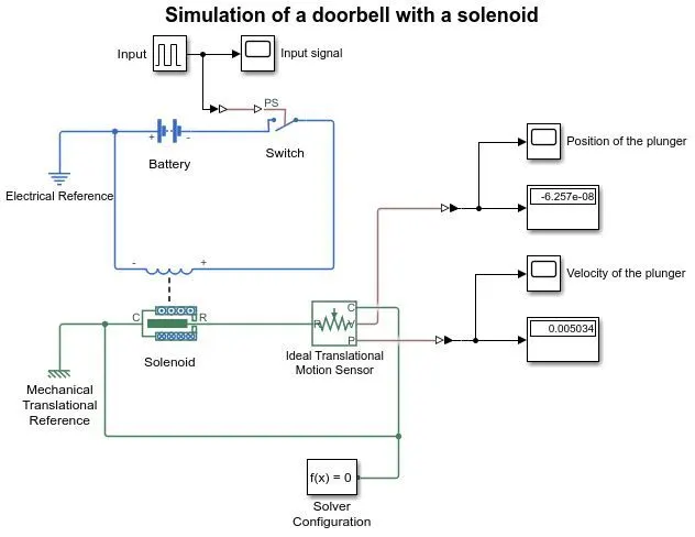
So using the theory of the electric bell and the solenoid, we move onto creating a Simulink model for the same. The Simulink blocks used are explained below.
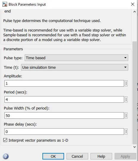
1.  Pulse generator - used as the input signal in this model. The inputs for this block is shown below.
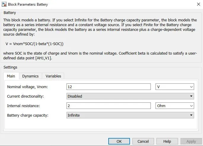
2.  Battery - this block is used as the voltage source in our circuit. The battery settings are uploaded as below.
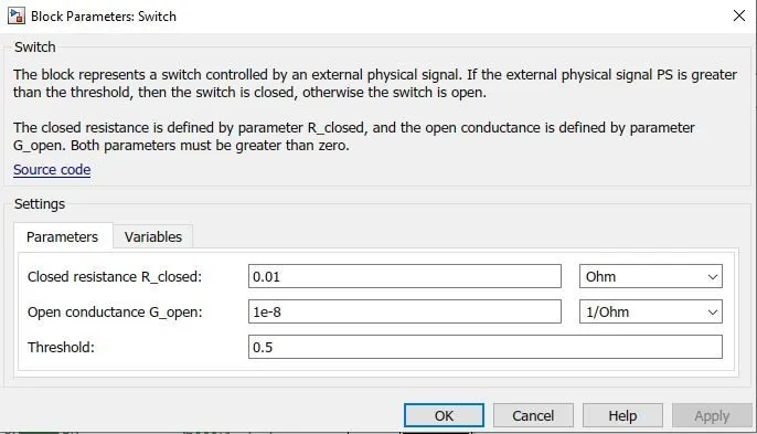
3. 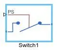 Switch - an electrical switch block is used for providing discontinuity in the circuit. The inputs for the block is shown below.
4. 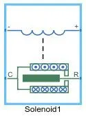 Solenoid - this block is used in our circuit representing a solenoid, inputs are varied and the result is observed.
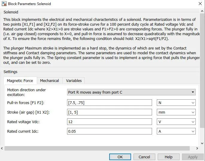
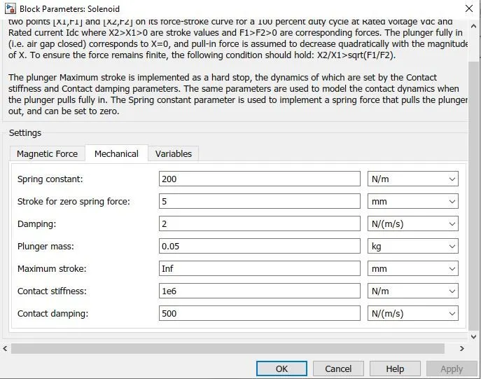
The mechanical parameters are varied to observe their effect on our results.
5. 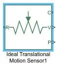 Ideal translational motion sensor - A sensor block is used in the model to observe the motion of the plunger which is basically a mechanical translational motion.
6. 
 We will also be using an electrical and a mechanical reference in our model to connect to a frame or ground.
PROCEDURE -
1. To create a model similar to the above diagram, we need to select the right blocks as explained above.
2. Firstly, we need to create an electrical circuit that will include the solenoid, so a battery with a voltage of 12V and a resistance of 2 ohms is connected to a solenoid.
3. An electrical switch is used to create a discontinuity in the circuit and also to satisfy the given requirement.
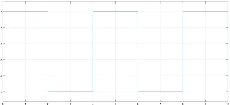
4. Physical signal input is needed for the switch, so we choose a pulse generator where we produce an input of amplitude 1, period 4sec and a pulse width of 50%. These input parameters for our pulse generator will satisfy the condition of the bell being rung every 2 seconds.
5. The input signal thus provided to the electrical switch is shown below
6. Once we input the physical signal, we complete our electrical circuit by connecting an electrical reference block.
7. We now decide and fix the solenoid parameters (we can vary the spring constant, the mass of the plunger, or the spring dampness).
8. Now we connect the plunger to an ideal translational motion sensor, to save the position and velocity values of the plunger and later connect it to the display and scope blocks to obtain the values and plot on our screens.
9. To complete our mechanical circuit, we connect the plunger to a mechanical reference and also add a solver configuration which helps in solving our governing equations.
10. Once we connect our Simulink blocks accordingly, we run the simulation and obtain our required results. The Simulink model of an electric bell with a solenoid is shown below.
RESULTS -
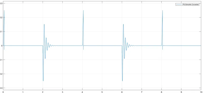
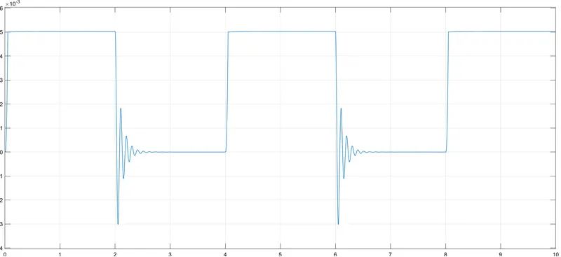
1. For a damping value of 1, a plunger mass of 0.05 kg, and a spring constant of 200.
The position of the plunger is shown below
The velocity of the plunger is shown below
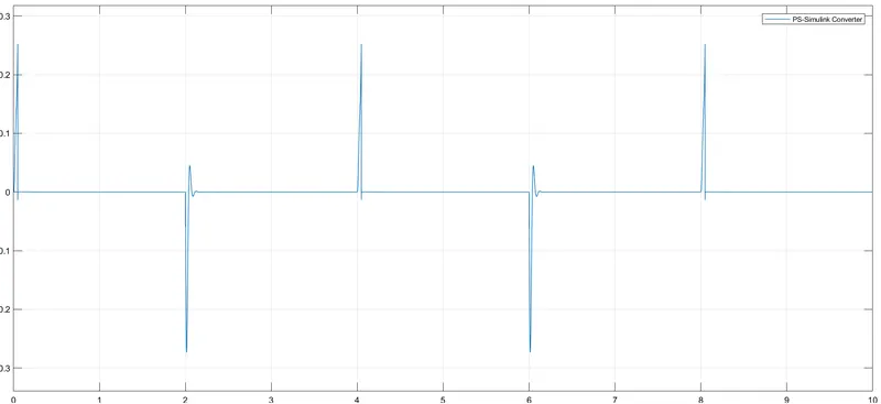
2. For a damping value of 2, a plunger mass of 0.02 kg, and a spring constant of 200.
The position of the plunger is shown below
The velocity of the plunger is shown below
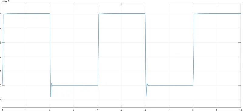
We can see that when we increasing the value of damping and the mass of the plunger, we get a more stable output.
3. The link to the Simulink file has been shared below.
https://drive.google.com/file/d/1vpVQc_-kloBjtZqZ-33fzhINTE09ta_4/view?usp=sharing
AIM - 2
2. To create a Simulink model of a thermistor to sense the temperature of a heater and turn the fan off or on as per the given conditions.
The conditions are -
Temperature source:
20 °C from 0 to 10 seconds, 27 °C from 10 to 30 seconds, 23 °C from 30 to 50 seconds.
Fan conditions:
ON if the temperature above 25 °C, OFF otherwise.
Before we make a Simulink model satisfying the above conditions, we need to learn about the thermistor and types.
THEORY -
A type of resistor whose resistance value is sensitive to the change in temperature is known as Thermistor. This is the passive component in the circuit. The material used in the construction of this differs from RTD’s. The thermistors are made by using Ceramic or polymers.
The temperature measured from this thermistor produces accurate values. These are of cheap and robust nature. But it doesn’t go well when we connect it in extreme cold and hot conditions. When the requirement is raised to maintain certain limited range thermistors are preferred. In the case of large temperature range RTDs are used because they are made up of pure metals.
Working principle of a thermistor -
Thermistors functioning is described as
- The principle obeyed by the thermistor is its dependency on-resistance values on the temperature change.
- The value of resistance can be measured by using an ohmmeter. These are connected in series with the battery and the meter.
- The change in the resistance is depending upon the material chosen in the construction of the thermistor.
- Thermistors are considered to be a special variety of resistors. Generally, the resistor is known for limiting the amount of current in the circuit.
- But in these thermal resistors, the change in the resistance is dependent upon the temperature change.
- If the temperature tends to increase the resistance in the circuit decreases in these special variants of resistors. It is decided based on the coefficient of temperature.
The thermistors are classified into two categories based on the type of temperature coefficient.
There are two types of temperature coefficients namely negative temperature coefficients and positive temperature coefficients. The ceramic semiconductor material used for each type of thermistor, differs, as the temperature coefficient is dependent on the material used.
NTC thermistor -
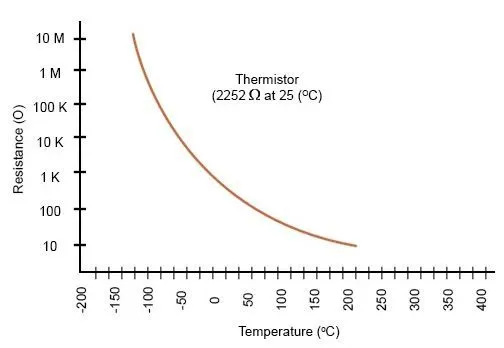
NTC or negative temperature coefficient thermistor is a device whose resistance decreases with an increase in temperature. These types of resistors usually exhibit a large, precise, and predictable decrease in resistance with an increase in temperature. Unlike other resistors (fixed or variable), these are made of ceramics and polymers, which are composed of metal oxides that are dried and sintered to obtain the desired form factor. In the case of NTC thermistors, cobalt, nickel, iron, and copper oxides are preferred.
A typical NTC thermistor gives the most precise readings in the temperature range of -55oC to 200oC. However, some specially designed NTC thermistors are used at absolute zero temperature(-273.15oC) and some can be used above 150oC. The figure below shows the characteristic curve of an NTC thermistor.
PTC thermistor -
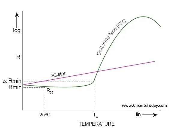
PTC or Positive temperature coefficient Thermistors are those resistors whose resistance increases with an increase in ambient temperature. PTC Thermistors are grouped according to their structure, materials used, and their manufacturing process. Silistors, are PTC Thermistors that belong to the first group(according to material used and structure). They use silicon as the semiconductor and have linear characteristics. Switching type PTC Thermistors belong to the second category (according to the manufacturing process). This Thermistor has a nonlinear characteristic curve. As the switching type, PTC Thermistor gets heated, initially, the resistance starts to decrease, up to a certain critical temperature, after which as the heat is increased, the resistance increases dramatically. The following figure shows the characteristic curve of a Silistor and a switching type PTC Thermistor.
In our Simulink model, we will be using an NTC thermistor, which will be explained further.
Before we make the model, we need to choose the right blocks and each of those blocks has been explained below.
1. 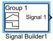 Signal Builder - this block is used as an input signal in our model as we have varying temperatures at different time intervals. This block is the perfect fit for our model.
2. 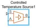 Controlled temperature source - this block is used as a temperature source for our thermistor in the model.
3. 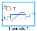 Thermistor - this block will be used for the connection with our controlled temperature source in the model. The inputs given to this block is shown below.
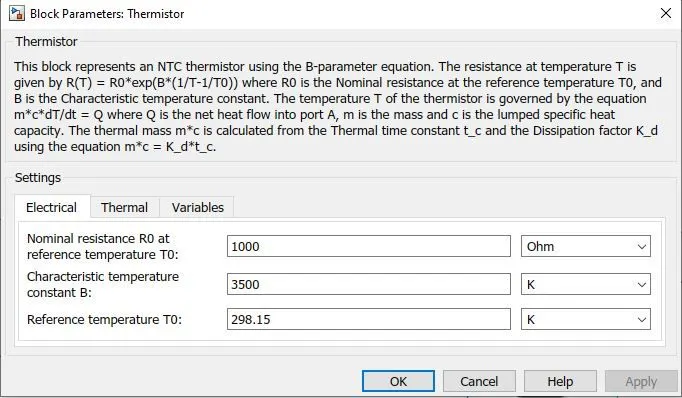
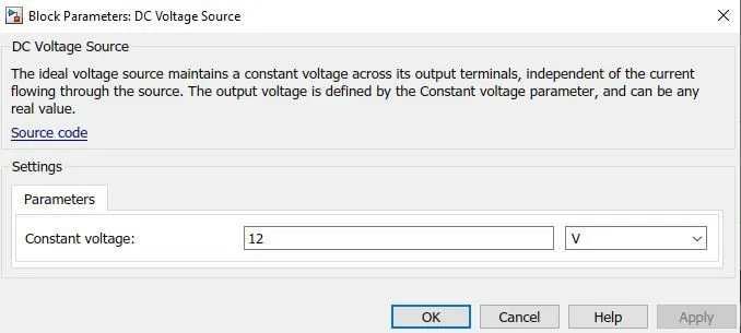
4. 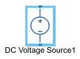 DC voltage source - this block acts as a voltage supply to the electrical circuit in the model. The input is provided below.
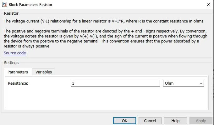
5.  Resistor - this block is connected to the thermistor and serves as a medium through which we can observe the variation in the thermistor. Basically, this block acts as an ohmmeter. The inputs are provided below.
6. 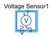 Voltage sensor - this block is used to check the voltage variation across the resistor which is connected with the voltage source.
7.  Switch - this block is used as an if & else statement that satisfies the required conditions. The first port is given an input of a constant value 1, the second port is given an input of a constant value 0. Hence, the block acts as an ON & OFF switch.
8.  Controlled voltage source - this block accepts the output of the switch and is connected to a DC motor (fan).
9.  DC motor - this block is used in the model to represent the fan. As the voltage source is connected, we will be able to observe the rotational motion as per our conditions.
10.  Ideal rotational motion sensor - this block is used as a sensor to observe the motion of the DC motor.
PROCEDURE -
1. Firstly, we need to select an appropriate temperature source and provide our input. For our temperature source, we will be using the controlled temperature source block.
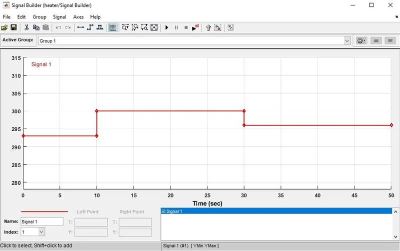
2. For the input, we will be using a signal builder and the input is provided below. 20 °C from 0 to 10 seconds, 27 °C from 10 to 30 seconds, 23 °C from 30 to 50 seconds.
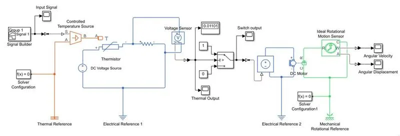
3. Now the temperature source is connected to the thermistor which is connected to another resistor and this circuit is powered through a DC voltage source of 12 V. A voltage sensor is connected across the resistor through which we can observe the voltage variations as the temperature varies.
4. The output of the voltage sensor is connected to a switch. This switch acts like an if & else statement in this model or more accurately an ON & OFF switch for our fan.
5. The output of the switch is connected to a controlled DC voltage source which in turn is connected to a DC motor.
6. The DC motor represents the fan in our model. An ideal rotational motion sensor is connected to our DC motor through which we can observe the results required.
7. We will be using the electrical, temperature, and mechanical rotational references wherever required in the model. The solver configuration block is also used wherever necessary.
8. After all the connections are made and inputs are fixed, the model will be ready.
The Simulink model for the heater is shown below.
RESULTS -
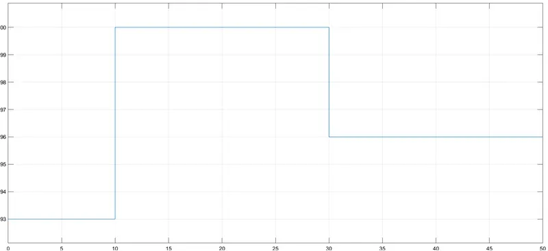
1. The input to the controlled temperature source through the signal builder is shown below. We can observe that the temperature from 0-10 seconds is 293K, temperature from 10-30 seconds is 300K, and the temperature from 30-50 seconds is 296K.
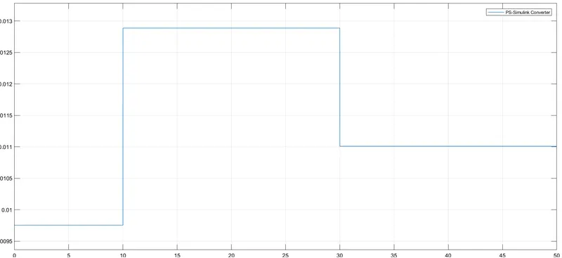
2. The voltage variation observed through the NCT thermistor is shown below. We can observe the voltage variation for the different time periods where the temperature varies.
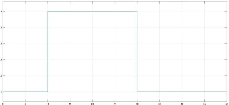
3. The output of the switch is shown below. We can observe that at the time period of 0-10 seconds, the switch is open (value 0 represents the switch to be open), at the time period of 10-30 seconds, the switch is closed (value 1 represents the switch to be closed), and at the time period of 30-50 seconds, the switch is open again.
4. The output of the DC motor when the switch is closed and opened is shown below.
The angular velocity of the DC motor is shown below.
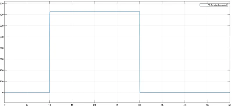
The angular displacement of the DC motor is shown below.
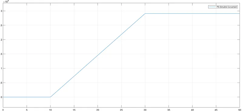
From the above 2 plots of the DC motor, we can observe that the fan is turned ON at the time period of 10-30 seconds i.e. when the heater reaches a temperature of 27 degrees Celsius (300K). The fan is turned off at the time periods of 0-10 seconds and 30-50 seconds i.e. when the heater is at a temperature of 20 degrees Celsius (293K) and 23 degrees Celsius (296K) respectively. Hence, the conditions were satisfied.
5. The Simulink file for the model has been shared below.
https://drive.google.com/file/d/11OJd1o_amip4msRsIZpPSit9LD9929to/view?usp=sharing
CONCLUSION -
The Simulink models of both the electric bell with a solenoid and the heater are created and its results are shared above.
REFERENCES -
1. https://byjus.com/physics/working-of-electric-bell/
2. https://circuitdigest.com/article/what-is-solenoid-its-working-principle-and-types
3. https://www.watelectronics.com/what-is-thermistor-working-types-applications/
4. https://www.circuitstoday.com/thermistors-working-types-applications