ELECTRIC DOOR BELL
- ELECTRIC DOOR BELL:
- AIM:
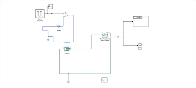
The main aim of the project is to create the simulink model of electric door bell using solenoid block set.
- OBJECTIVE:
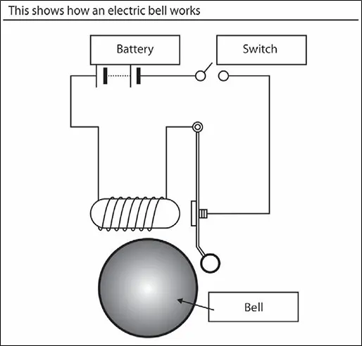
An electric bell is a mechanical or electronic bell that functions by means of an electromagnet.When an electric an electric current is applied,it produces a repetitive buzzing,clanging or ringing sound . Electric bells have been widely used at railroad crossing,fire and burglar alaram,as schools bells,doorbells,and alarams in industrial plants,since late 1800s,but they are now being widely replaced with electronic sounders.An electric bell consists of one or more electromagnets,made of a coil of insulated wire around an iron bar,which attract an iron strip armature with a clapper.When an electric current flows through the coils ,the electromagnet creates a magnetic field which pulls the armature towards it,causing the hammer to strike the bell.
- SIMULINK BLOCK:
- INPUT SIGNAL:
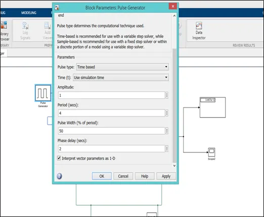
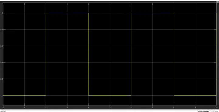
To provide the input signal pulse generator is used and input pulse should be zero for every 2sec which represents an off condition so we create a pulse by changing the period to 4 which includes both on and off condition and pulse width to 50(how much period should the switch is in on condition) and phase delay of 2sec.Output of the pulse generator is connected to scope which represents the input signal.
2. The output is connected to the switch using simulink PS converter which convert the simulink signal to physical signal and further it is connected to the switch. Battery and switch forms an electric circuit hence electric reference is provided.
3. A solenoid is a type of electromagnet ,the purpose of which is to generate a controlled magnetic field through a coil wound into a tightly packed helix.The coil can be arranged to produce a uniform magnetic field in a volume of space when an electric current is passed through it. In our simspace block we used solenoid which is just an electromagnet where the coiled wire surrounds a metal piston.The piston contains magnetically conductive metal,so it can be moved backward or forward by electromagnetic field.
4. Ideal Transational motion sensor is used to sense the movement of plunger when their is a electric supply.
5. Display block indicates the position of plunger.
- OUTPUT:
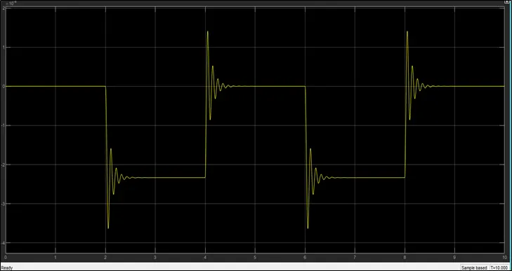
This is because of damping parameter will take the default value as one which is not for critical damped value and it is calculated by the formulae `2*sqrt(k*m)` where k is stiffness of the spring and m is mass of plunger`
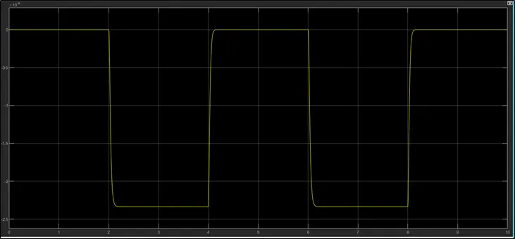
The above plot shows the position of plunger for initial 2 sec in which the switch is in off condition the plot is constant which indicate their is no deflection in the plunger and from 2-4 sec the plunger is in more negetive position which indicate the plunger deflection and negative is because the plunger is move towards the bell.
- CONCLUSION:
The simulink model of door bell using solenoid blockset is obtained.
- THERMISTOR CONTROLLED FAN:
- AIM:
The main aim of the project is to create the simulink model to sense the temperature of heater and turn on or turn off the fan as per below condition.
- Fan is on when temperature is more than 25 degree celsius,off otherwise
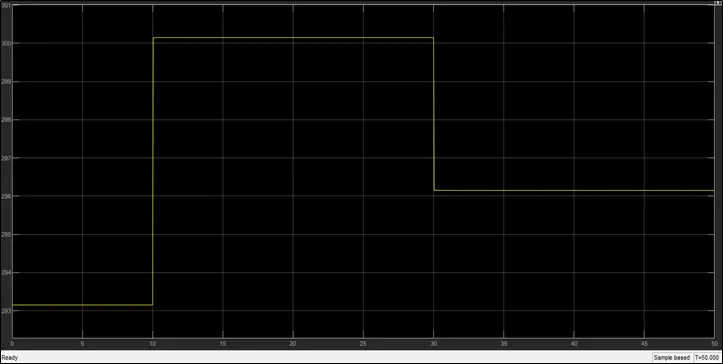
- Temperature source: 20 °C from 0 to 10 seconds, 27 °C from 10 to 30 seconds, 23 °C from 30 to 50 seconds
- OBJECTIVE:
A thermistor is a resistance thermometer,or a resistor whose resistance is dependent on temperature.The word is a combination of thermal and resistor.Thermistor are of two opposite fundamental types
- With NTC thermistor , resistance decreases as temperature rises.An NTC is commonly used as a temperatute sensor,or in series with a circuit as an current limiter.
- With PTC thermistor ,resistance increases as temperature rised.PTC thermistor are commonly installed in series with a circuit, and used to protect against overcurrent condition,as resettable fuse.
- SIMULINK MODEL:
- EXPLANATION:
Initially we have to create the model for the reference temperature which is 25 degree celsius and get the corresponding voltage value which is consider as a threshold value for the further model.
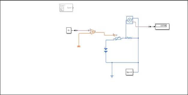
The constant value is 298.15k which is the reference temperature and it is connected to the controlled temperature block using simulink PS converter.In simlink PS converter we assume as a first order approximation,that the relationship between resistance and temperature is linear.Controlled temperature block represents an ideal energy source in a thermal network that can maintain a controlled temperature difference regardless of the heat flow rate. The temperature difference is set by the physical signal port S. A positive temperature difference causes the temperature at port B to be greater than the temperature at port A.Port A is connected to the thermal reference and controlled temperature block is further connected to the Negetive thermal coefficient NTC thermistor.Resistor and voltage sensor is connected in series and output of voltage sensor is obtained in display on running the simscape block and the value obtained is the threshold value which is further used in modelling.
Temperature source signal is provided by signal builder which creates and generates interchangable signals whose waveforms are piecewise linear as shown in below plot,
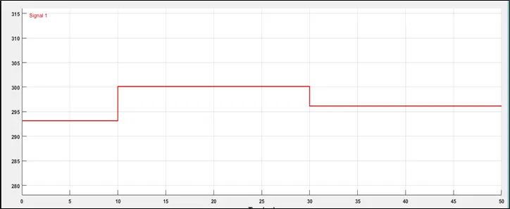
OUTPUT FROM SIGNAL BUILDER:
NEXT STEP
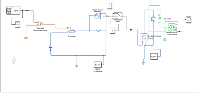
Out put from the voltage sensor is connected to the switch through simulink PS converter in switch block parameter threshold value has to entered which is obtained previously .The first and third input ports are data ports, and the second input port is the control port.Constant block 1 and 0 for switch on and switch off condition respectively.when the condition is satisfied in control port then signal flow through the constant 1 block otherwise constant 0 block.
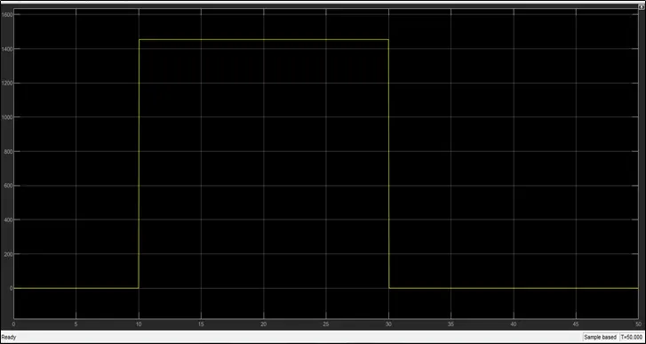
Output from switch is connected to the controlled voltage source block which supplies voltage to the DC motor which is the replica of Fan and further DC motor is connected to the ideal rotational motion sensor which sense the angular motion of DC motor/fan and records it in scope as output.In this two solver configuration block is used because the first solver configuration is intruppeted by simulink PS converter.
- OUTPUT:
- CONCLUSION:
From the plot Initially from 0-10 sec the plot is linear because the temperatute value is 293.15k which is less than the reference value hence the fan is in off condition and in the time period from 10-30 sec the variation is observed because the temperature value is 300.15k which is greater than the reference value hence the fan is in on condition and during time period 30-50 sec the plot is linear and value is 0 and the corresponding temperature value is 296.15k which is less than the reference value hence the fan will be in off condition.