Week -2
Aim:
To make a doorbell model with Simulink blocks and observe the movements of plunger when the switch is operated and closed for every two seconds and released and also to make the Simulink model which uses Thermistor to sense the temperature of heater and turn on or off the fan.
Procedure:
Working of Doorbell:
The doorbell using here is a electromagnet called a solenoid. A solenoid is a type of electromagnet where the coiled wire surrounds a metal piston. The piston contains magnetically conductive metal, it can be moved backward or forward by the electromagnetic filed. Solenoid purpose is to generate a controlled magnetic field. The term solenoid was first coined by Andre-Marie Ampere.
Simulink Block Explanation:
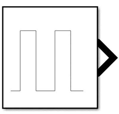
1.Pulse Generator:
The Pulse Generator block generates square wave pulses at regular intervals. The block waveform parameters, Amplitude, Pulse Width, Period, and Phase delay, determine the shape of the output waveform. The following diagram shows how each parameter affects the waveform.
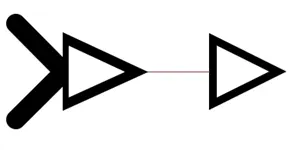
- Simulink to PS Convertor:
The Simulink-PS Converter block converts the input Simulink signal into a physical signal. Use this block to connect Simulink sources or other Simulink blocks to the inputs of a Physical Network diagram.
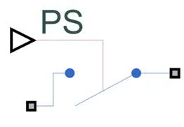
3.Switch:
The Switch block models a switch controlled by an external physical signal. If the external physical signal PS is greater than the value specified in the Threshold parameter, then the switch is closed, otherwise the switch is open.
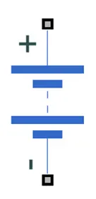
4.Battery:
The Battery block represents a simple battery model. The block has four modeling variants, accessible by right-clicking the block in your block diagram and then selecting the appropriate option from the context menu
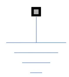
5.Electrical Reference:
The Electrical Reference block represents an electrical ground. Electrical conserving ports of all the blocks that are directly connected to ground must be connected to an Electrical Reference block. A model with electrical elements must contain at least one Electrical Reference block.
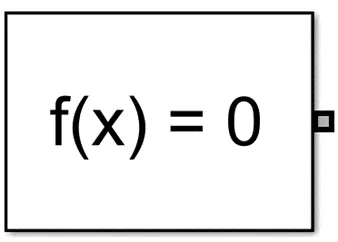
6.Solver Configuration:
Each physical network represented by a connected Simscape block diagram requires solver settings information for simulation. The Solver Configuration block specifies the solver parameters that your model needs before you can begin simulation.
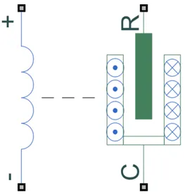
7.Solenoid:
The Solenoid block represents the electrical characteristics and generated force. The return spring is optional. To remove the effects of this spring from the model, set the Spring constant parameter to 0. To show the direction in which the solenoid acts, the block icon changes dynamically based on value of the Motion direction under excitation parameter.
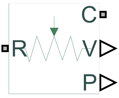
8.Ideal Translational Motion Sensor:
The Ideal Translational Motion Sensor block represents a device that converts an across variable measured between two mechanical translational nodes into a control signal proportional to velocity or position. You can specify the initial position (offset) as a block parameter.
9.Mechanical Translational Reference:
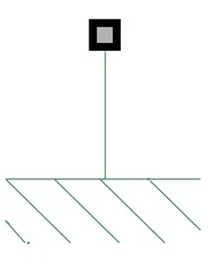
The Mechanical Translational Reference block represents a reference point, or frame, for all mechanical translational ports. All translational ports that are rigidly clamped to the frame (ground) must be connected to a Mechanical Translational Reference block.
10.PS to Simulink Convertor:
The PS-Simulink Converter block converts a physical signal into a Simulink output signal. Use this block to connect outputs of a Physical Network diagram to Simulink scopes or other Simulink blocks.To convey signal conversion while taking up minimal canvas space, the block icon changes dynamically based on whether it is connected to other blocks.
11.Scope:
The Simulink Scope block and DSP System Toolbox Time Scope block display time domain signals.
12.Display:
The Display block shows the value of the input data. You can specify the frequency of the display. For numeric input data, you can also specify the format of display.
To convey signal conversion while taking up minimal canvas space, the block icon changes dynamically based on whether it is connected to other blocks.
In the given model, a square pulse is generated with a time delay of 2 seconds and is passed to switch control. The switch is controlled by the pulse generator. When the threshold value is less than the physical signal value the switch closes and forms a closed circuit. The electric current is passed from the battery to solenoid as soon as the circuits gets closed. The solenoid which contains piston inside of it has a iron core mounted on non-mettalic metal bar. When there is no power to the electromagnet the spring pushes back to the piston and the iron core remains outside of the wire coil. When we turn ON the electromagnet by passing current, the iron core is drawn into the magnetic filed. The iron core slides into the coil and strikes the end of the piston to the one hand tone bar. which vibrates and produces the 'ding' sound. As long as we hold the doorbell button, the current will flow through electromagnet and the piston remains in this position. Here the generated pulse is supplied to the switch for period of 2 seconds. So after two seconds get over the connection breaks and circuit becomes open. That means current will stop flowing through the electromagnet and magnetic field collapse. The spring snaps the piston back to the initial position, where it hits the other tone bar on the other side. The second tone bar produces the 'dong' sound. The process is repeated untill the last given pulse is generated.
The total time duration for the signal is set as 10seconds and pulse is generated for every 2seconds. During this period of observation the graphically results is taken which can been seen in Scope 1 and Scope 2 in the Simulink block.
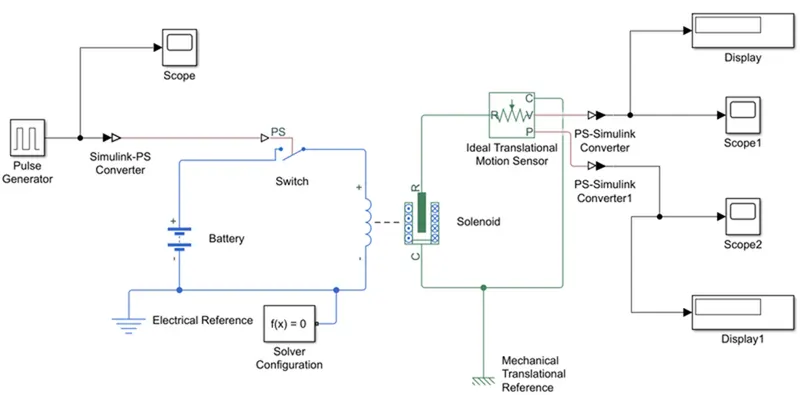
Once the Simulink blocks are created it is made to run and below results are obtained.
Output:
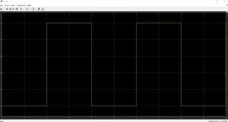
Scope1: Shows the pulse generating X-axis represents the 'Time', Y-axis represents the 'Amplitude'.
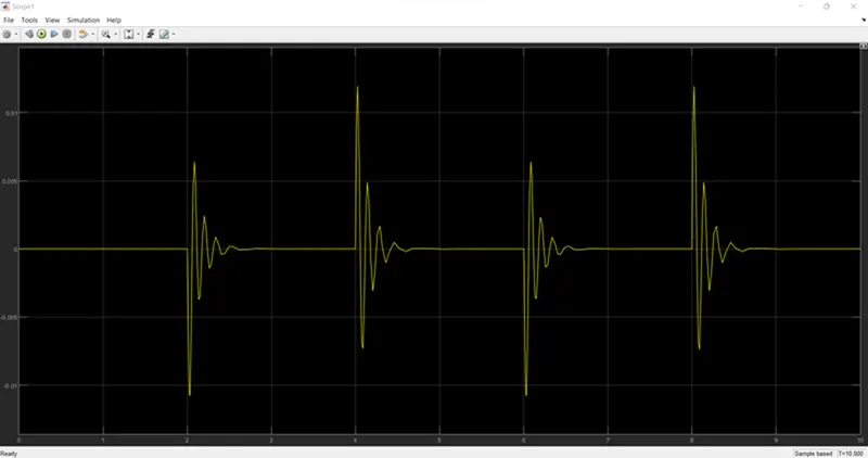
Scope2: The below graph shows the vibrations produced by the tone bar at every 2 seconds.
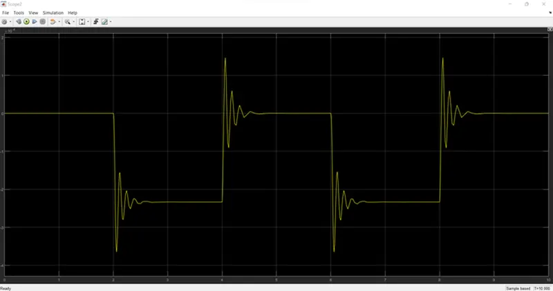
Scope3: Here X-axis represents the 'Time, Y-axis represents the 'Plunger'. The inkitial position of plunger is at 5mm as from pulse generator block, a pulse generated at 2, so in the position of the plunger is also changing at time 2 seconds and time till which the pulse amplitude is '1' till that time plunger is also at the same position after the change from initial position.
Thermistor and its working principle:
A Thermistor is a type of resistor whose resistance is strongly dependent on temperature, more so than in standard resistors. Thermistor is a temperature sensing element made of semiconductor material which exhibits a large change in resistance proportional to the small change in temperature. There are two types of Thermistors which are explained below:
Positive Temperature Co-efficient Thermistor, whose resistance increases with increase in temperature.
Negative Temperature Co-efficient Thermistor, whose resistance decreases with increase in temperature.
Thermistor works on a principle that when a constant current flowing through the resistor and its changing resistance due to change in temperature is measured as a voltage drop across it.
Thermistor resistance-Temperature relationship can be dR=K*dT, where k is temperature coefficient, dR is change in resistance and dT is change in temperature.
The negative temperature coefficient allows the thermistor circuit to detect minute changes in temperature which could not be observed by the other thermocouple circuits. Maximum limit of temperatures can be measured up to 100 degree to 200 degrees.
Resistor:
Resistor is an electronic components that limits or regulates the flow of electric current in an electronic circuits. This resistors are used to provide the specific voltage for an active device such as thermistor which is also a resistor.The resistance towards the flow of current will result in voltage drop. R = V/I, where R is resistance, V is voltage & I is current.
Electric current can be calculated by measuring the voltage drop over a precision resistor with a known resistance which is connected in series with the circuit.
Procedure:
Thermistor which is using as a temperature sensor will measure the temperature of heater and instruct the fan which is mechanical energy source or DC motor taken, should be ON or OFF depending on the given conditions.
Thermistor Simulink Model:
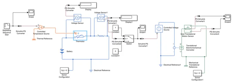
Using repeating sequence star block a pulse is generated, which is range of temperature given imn an array with a sample of 10seconds and the total of signal generated to observe is for 0 second, of which 20 °C from 0 to 10 seconds, 27 °C from 10 to 30 seconds, 23 °C from 30 to 50 seconds. This signal is given to the thermistor through controlled temperature source block, two inputs are given to the thermistor which is controlled temperature source & electric current from battery. Once the temperature of the thermistor resistor increases, the number of active charge carriers number of charge carrier increases which promotes them into the conduction mode. As the NTC thermistor, when temperature increases the resistance decreases.
Here the Simulink blocks starts Thermistor is Repeated sequence stair as the different temperatures are given in array format which is connected to the Simulink to PS converter to change the signal as this is attached to the scope to monitor the different tempearture for different time sample, once the signal is converted it is linked with the Controlled Temperature Source block where the ideal energy source in a thermal network that can maintain a controlled temperature difference regardless of the heat flow rate. The temperature difference is set by the physical signal port S. A positive temperature difference causes the temperature at port B to be greater than the temperature at port A. As the A port is connected to the thermal reference in which the B port is connected directly to the thermistor. As the Thermistor block represents an NTC thermistor using the B-parameter equation. The resistance at temperature T is given by R(T) = R0*exp(B*(1/T-1/T0)) where R0 is the Nominal resistance at the reference temperature T0, and B is the Characteristic temperature constant. The temperature T of the thermistor is governed by the equation m*c*dT/dt = Q where Q is the net heat flow into port A, m is the mass and c is the lumped specific heat capacity. The thermal mass m*c is calculated from the Thermal time constant t_c and the Dissipation factor K_d using the equation m*c = K_d*t_c. The positve part of the thermistor is connected to the battery and the negative part to the resistance which in loop is connected to the other end of the battery. Here in between the thermistor voltage sensor is connected between the thermistor and the it is been set up such a way that the voltage drop can be observed graphically. Same setup is kept for the resistance as the voltage sensor is provided in which the voltage is connected to the switch were the ON and OFF signal is operated, which is observed through graph. The switch is linked with the controlled voltage source which in loop connected to the translational electromechanical converter as the electrical reference is linked in between the loop. Translational electromechanical converter is linked with ideal translational motion sensor as this result is taken as a graphically. The Simulink model is shown below
Output:
1.Voltage vs Time
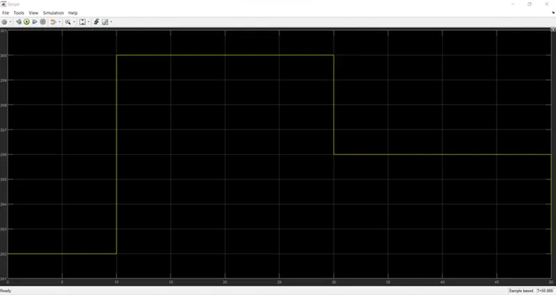
The above result shows difference in temperature with different time period
2.Voltage vs Switch
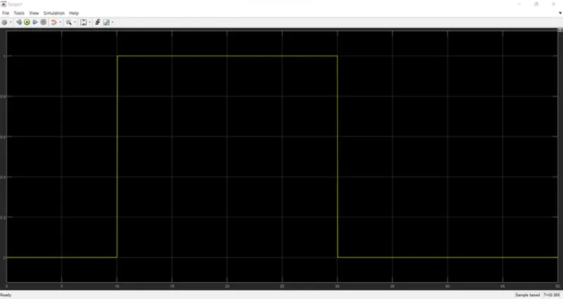
The voltage value which is obtained at operating temperature sensed by thermistor and pass to switch block. If the value is less than zero the current will pass to the fan and it is ON mode. If the value is less than zero, it is OFF mode.
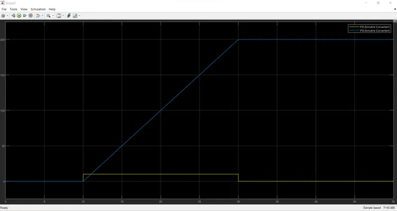
3.The graph shows the velocity and displacement of DC motor
Conclusion:
The above experiments are the results of how the doorbell rings using Solenoid Simulink Block, graphical results are attached and by using the thermistor to sense the temperature of a heater & turn on or turn off the fan according to different time and temperature given, the graphical results are also attached.