Week -2
Objective -
- Make a Simulink model of Doorbell using solenoid block
-
Use a thermistor to sense the temperature of a heater & turn on or turn off the fan
Report
1. Make a Simulink model of Doorbell using solenoid block
Working principle of doorbell using solenoid
A chime doorbell uses a specialized sort of electromagnet called a solenoid A solenoid is just an electromagnet where the coiled wire surrounds a metal piston. The piston contains magnetically conductive metal, so it can be moved backward or forward by the electromagnetic field. The common chime design uses a solenoid to hit two tone bars in sequence.
In many instances, the solenoid piston consists of an iron core mounted to a non-magnetic metal bar. When there is no power to the electromagnet, a spring pushes the piston to the left, and the iron core extends outside of the wire coil. When you turn the electromagnet on (by pressing the doorbell button), the iron core is drawn to the magnetic field, so it slides into the center of the coiled wire.
As the iron core slides to the right, the end of the piston strikes the right-hand tone bar. The tone bar vibrates, producing a particular note. This is the "ding" sound.
As long as you hold the doorbell button, current will flow through the electromagnet and the piston will remain in this position. But when you release the button, the current will stop flowing through the electromagnet and the magnetic field will collapse. The spring snaps the piston back to the left, where it hits the tone bar on the other side. The second tone bar produces the "dong" sound.
Blocks in the model-
- Pulse Generator.
- Switch.
- Battery.
- Solenoid.
- Ideal Translational motor sensor.
- Mechanical translational reference.
- Electrical reference.
- Scope.
Simulink Model
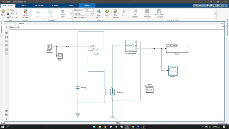
- To create a circuit an input values are connected for power supply here pluse generator are used as input block. Scope1 were connected to pluse generator to execute graph for input.
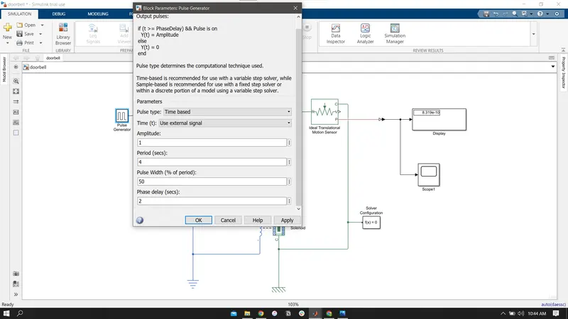
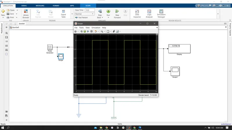
- Simulink to ps convertor connects the pluse generator and switch block. One end of switch is connected with battery and other with solenoid.
- The Solenoid block represents the electrical characteristics and generated force for the solenoid. It converts the electrical characteristics to mechanical.
- Now the plunger in solenoid are connected to ideal translational motion sensor. The block represents an ideal mechanical translational motion sensor, that is, a device that converts an across variable measured between two mechanical translational nodes into a control signal proportional to velocity and position.
- A case mechanical in solenoid is connected to ideal translational motion by the reference of mechanical translational. The solver also connected in this circuit for execute circuit without error.
- An output from ideal translational motion sensor are connected with scope by using Ps-simulink convertor.
Output
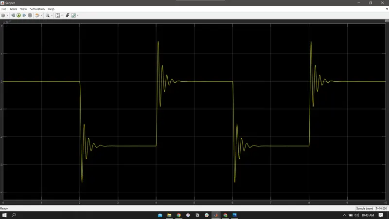
When the switch is closed the solenoid block receives electrical power from the battery and plunger moves from port R to port C to hit the bell & produce sound. Physical movement of the plunger is observed by using translational motion sensor & physical output is converted into Simulink output model is displayed in the scope. By reducing the spring constant value and increasing the damping value vibrations will be reduced.
2. Use a thermistor to sense the temperature of a heater & turn on or turn off the fan
A Temperature Controlled Fan is a system which automatically turns on a DC Fan when the ambient temperature increases above a certain limit.The key component of this temperature controlled fan circuit is Thermistor, which has been used to detect the rise in temperature. Thermistor is temperature sensitive resistor, whose resistance changes according to the temperature. The main principle of the circuit is to switch on the fan connected to DC motor when the temperature is greater than a threshold value.
Simulink model
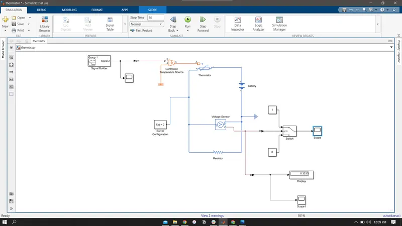
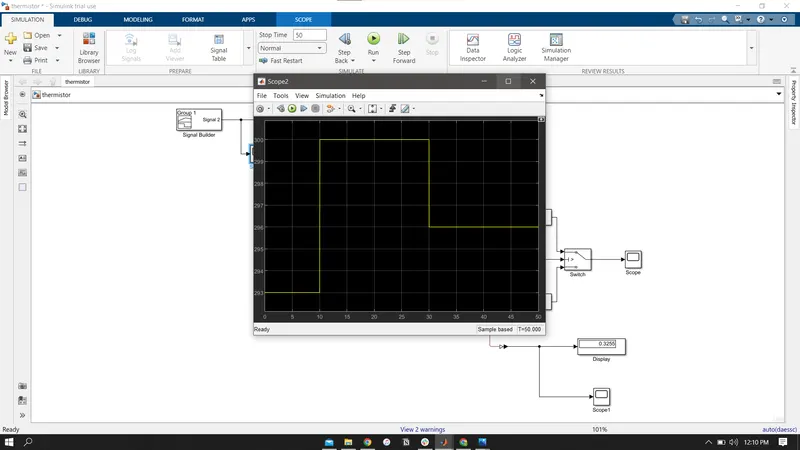
The Signal Builder block allows you to create interchangeable groups of piecewise linear signal sources and use them in a model. You can quickly switch the signal groups into and out of a model to facilitate testing. In the Signal Builder window, create signals and define the output waveforms.
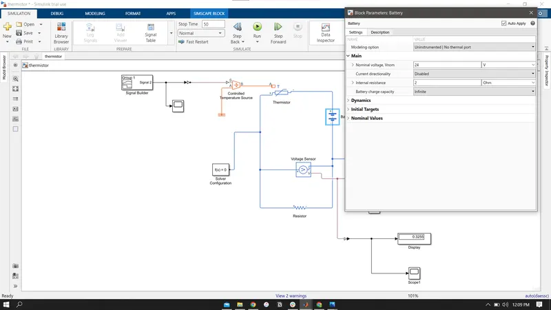
- An power supply like battery and current sensor is connected with the thermistor. And negative side are connected with electrical reference where solver also intitate in this circuit to obtain output.
-
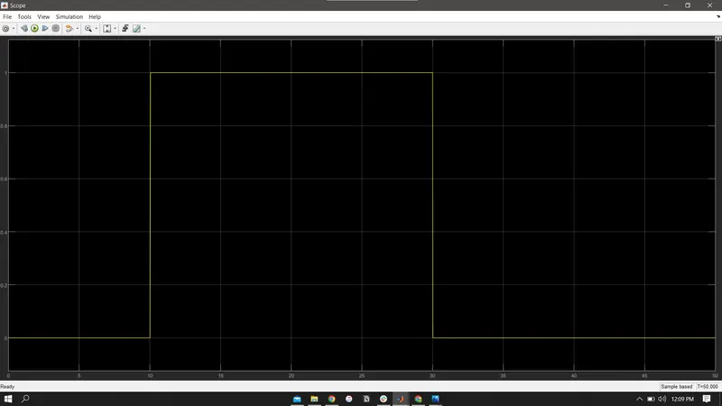
Temperature source: 20 °C from 0 to 10 seconds, 27 °C from 10 to 30 seconds, 23 °C from 30 to 50 seconds
Fan conditions: ON if the temperature above 25 °C, OFF otherwise
- Thermistor is used to sense the temperature of a heater & turn on or turn off the fan as per above conditions
-
Therefore the fan conditions are executed by SWITCH block and plotted in scope block.
Resulatant Plot