Simulate a simple math function using Simulink
Aim:
- To plot the function y(x) = (x-1) * (x-3)^2 * (x-9)^2 using basic Simulink blocks.
- To run Simulink example “Suspension comparison System” and to explain objectives of the simulation, similarities, and differences between three systems, observations on the simulation and how is the oscillating velocity source is created.
Description:
Part 1: To plot the given function using Simulink basic blocks.
The function y(x) is a basic mathematical function, which was built with the help of mathematical basic blocks in Simulink as shown below. The inputs for “x” was given as a “Ramp” which varied with respect to the number of time given to run the simulation. The time given to run the simulation was 10 seconds.
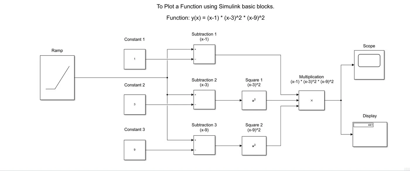
The answer observed in the display block at the end of the simulation was 144. And the graph observed in the scope block is as shown below.
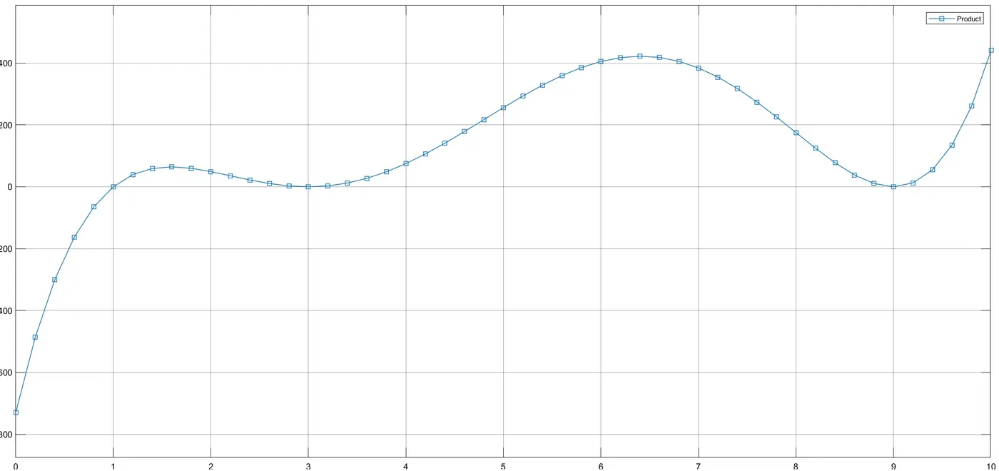
Whenever Simulink calculated the function y(x) at each point, it plotted that point in the graph which ranged from -800 to 400 and then a continuous line plot was formed joining all the points ending at the point 441 at 10th second. As shown in the graph the plotted points are shown as a square box point.
Part 2: To run Simulink example Suspension System Comparison simulation.
The Simulink model for Suspension System Comparison is as shown below.
Objective of this study:
The objective of this study was to understand the behaviour of three suspension system under one excitation source and to study how they behave when similar oscillation velocity is given to three different suspensions.
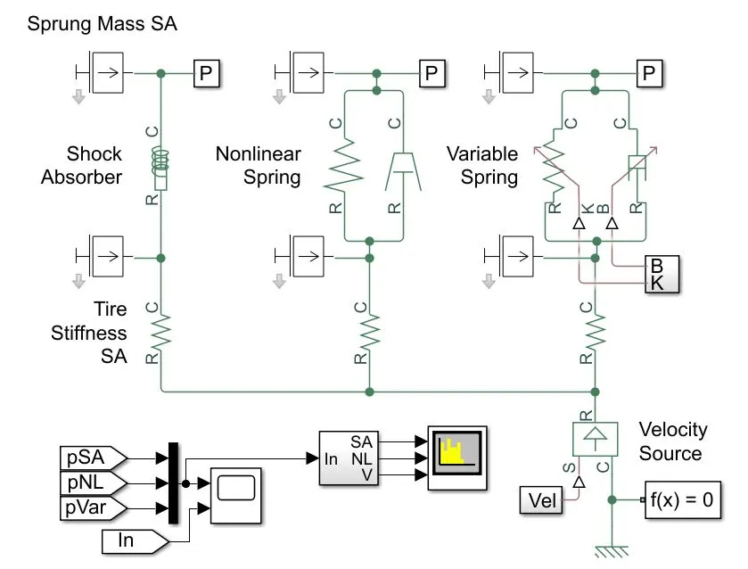
A suspension system consists of various different parts to form a single suspension system. Here as shown in the Simulink block system above, we are looking at three different suspension systems. The suspension system consists of various parts such as springs, dampers, shock absorbers, tyres etc. which is used to improve the quality of driving in any given vehicle. In the system shown above we are comparing a shock absorber, non-linear spring and a variable spring which has stiffness and damping added to it. These systems are excited with the help of oscillating velocity which is externally designed to excite the suspension systems.
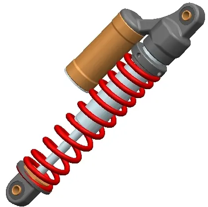
Shock Absorbers: They are a part of a suspension system which are hydraulic pump like devices that help to control the movement (impact and rebound) of vehicle’s springs and suspensions. The key role of shock absorbers is to keep the tyres of the vehicle maintain contact with the road, which is the only part of the vehicle that is in contact with the road surface. Also, they ensure the safest control of the vehicle during control and braking responses of the vehicle [1]. A shock absorber can be seen in the figure below [2].
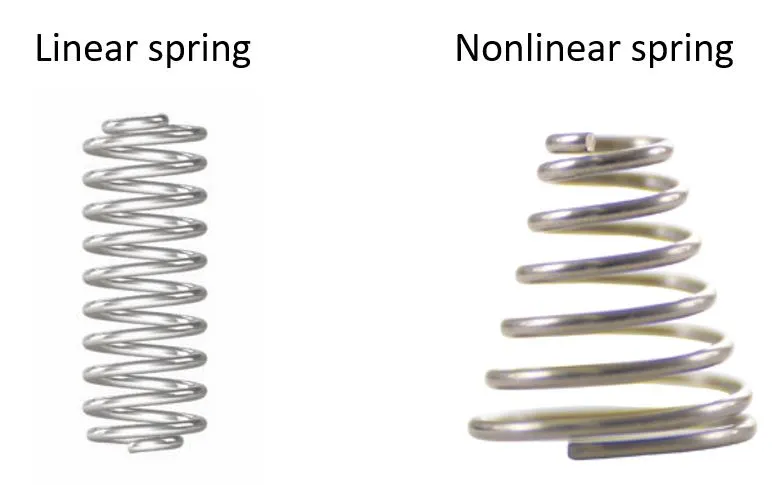
Nonlinear Spring: A nonlinear spring has a nonlinear relationship between force and displacement when seen in a graph of force vs displacement, it is observed to be a changing slope and not a straight line. These springs are not in a constant straight shape which can be seen below in comparison to the linear spring. These springs exert inconsistent amount of force which is under a working load or torque i.e. the force needed to travel one inch or degree maybe not the double amount of force when it has to travel two degrees or inches. Wherein, in a linear spring the force needed to travel 1 inch will be twice as the force to travel 2 inches [3].
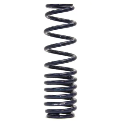
Variable Spring: In variable springs the springs are closer at some point and have a widened space at other points. Which means variable spring provides lower spring rate under unloaded conditions giving a smooth ride and high spring rate under loaded conditions giving stability and control and support to the vehicle. The figure of a variable spring can be seen below [4].
Common Oscillating Velocity exciter source:
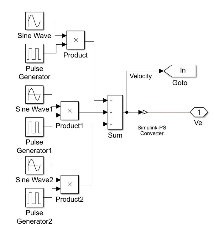
As shown in the above figure which is the common source oscillating velocity to all the three systems which in the block diagram can be seen at the bottom right hand of the diagram and is connected to all the three systems. In this block the Sine Wave and Pulse generator are combined to create an oscillating velocity with respect to time. Here three sine wave and pulse generators are used which are multiplied and is added before connecting to the inputs of the suspension systems.
Similarities between three systems:
As observed in the Simulink model of all the three mechanisms, the sprung and unsprung masses are same in all the three models. The oscillating velocity exciter is common for all the three systems and tire stiffness is same in all the three systems that is 2×10⁵ N/m.
Dissimilarities in three systems:
All three systems has three different kind of mechanisms that is, Shock Absorber, Nonlinear Spring and Variable Spring, which affects the displacement and force generated by the systems.
Observations in the graph plots:
Plot 1: Sprung Mass Position
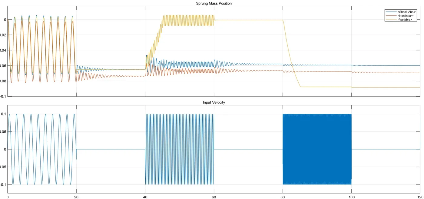
The variations were observed in the graph plots in the time 0 to 120, wherein for initial 20 seconds the sprung mass of all the three systems has almost the same variation, also the input velocity is present but has not so dense input for the first 20 seconds. The input velocity is absent for the second 20 seconds that is from 20 to 40 seconds, therefore the displacement is almost negligible as seen on the top graph. Thereafter in the time range of 40-60 seconds the input velocity comes into excitation again where variable spring shows a higher variation and the other two has almost constant variation. Again, in the 60 to 80 seconds frame there is no input velocity and therefore no displacement is observed. In the frame of 80 to 120 seconds the variable spring is observed to have a least distortion and when seen overall time frame the shock absorber is observed to have a very stable nature of plot.
Plot 2: Power Spectral Density (dBm/Hz) vs Frequency (Hz)
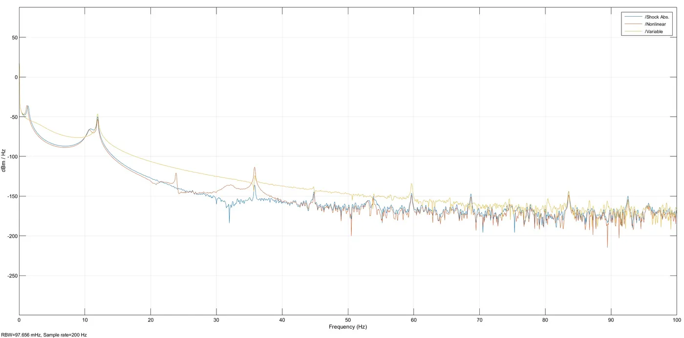
As seen in the above power spectral density versus frequency plot, it is observed that as the frequency increases the power spectral density increases. This graph of spectrum analyser illustrates the analysis of noise levels per frequency. The nonlinear spring is observed to behave/perform the best of all three systems.
Conclusion:
From the above studies of both the plots it can be said that the shock absorber performs well compared to other two systems. Displacement is inversely proportional to the spring stiffness. In any which cases or in the real world in vehicles, mostly the shock absorbers are used, as it is better in controlling the vehicle, also gives stability in driving, which gives good damping to the vehicle and increases the efficiency of the vehicle.
References:
[1] https://www.monroe.com.au/what-are-shocks/shock-absorbers-explained.html
[2] https://images.app.goo.gl/EKU4dGrBGxVhHLED6
[3] https://www.motioncontroltips.com/what-are-linear-springs-and-how-do-they-work/
[4] https://images.app.goo.gl/TzU7fM5RgbMQEnLs9