Simulink model of doorbell and sensing temperature using thermistor.
Q: Make a Simulink model of Doorbell using solenoid block with the following details:
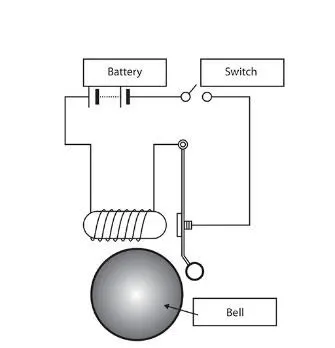
In the above arrangement, when the switch is closed the electromagnet receives electrical power from the battery and pulls the metal arm to hit the bell producing sound.
Create a situation where the switch is closed for 2 seconds and then released. Observe the physical movement of the plunger.
Q2: Use a thermistor to sense the temperature of a heater & turn on or turn off the fan as per below conditions:
- Temperature source: 20 °C from 0 to 10 seconds, 27 °C from 10 to 30 seconds, 23 °C from 30 to 50 seconds
- Fan conditions: ON if the temperature above 25 °C, OFF otherwise
A: Aim: To construct a Simulink model using solenoid when the switch is closed for 2 seconds by assuming some parameters. Construct a model in Simulink using a thermistor under certain temperature conditions and time.
Model 1: Doorbell
Description: Doorbell is constructed by using solenoid, battery, switch. The current supply is sent through the circuit by the battery source when the switch is closed. The current is supplied continuously when the switch is closed. This means the bell rings continuously when the switch is closed.
Doorbell mechanism: When the switch is closed, the current supply from the battery passes through the circuit and enters into the solenoid. The solenoid works under the principle of electromagnetism. The current passes through the spring, due to this electromagnetism induces in coils. This force moves the plunger aside. The plunger hits the metal and the metal produces sound with damping.
Model creation:
- Open Simulink from the MATLAB and save the model.
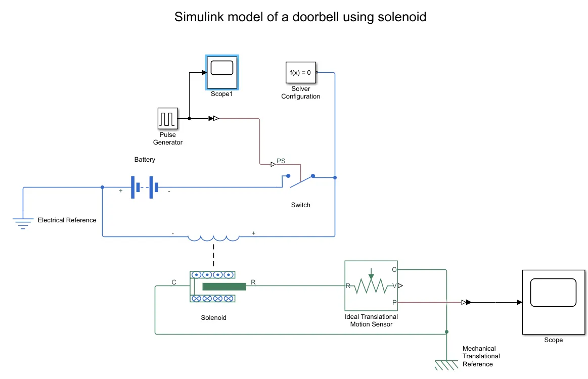
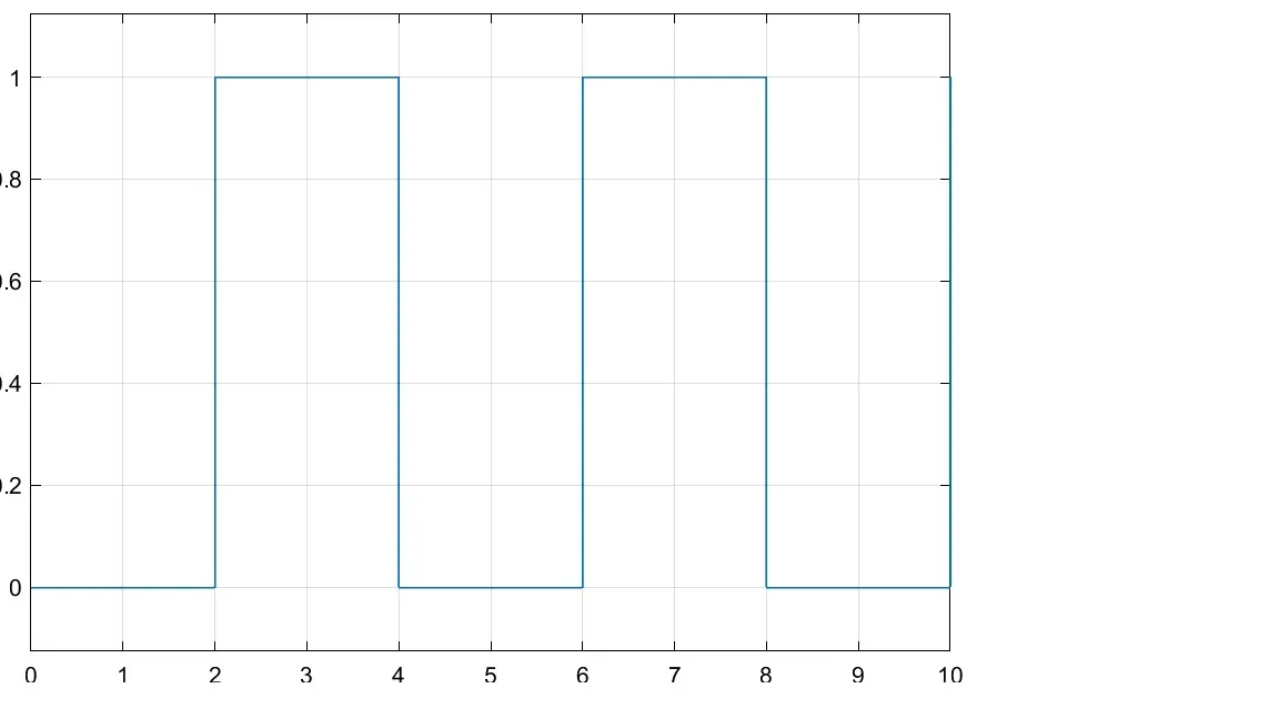
- First, we need to add the switch for the system. Add a switch(of electricals) from the library. The switch contains 3 joints. The switch should be operated for 2 seconds. This operation can be done by adding a pulse generator block with a phase delay of 2 seconds. Give amplitude 1 and phase width as 50% and frequency 4.
- The Simulink system should be converted into a physical system for operating the switch. Add Simulink-PS convertor add join all connections to switch as shown.
- For knowing the pulse given to the switch, we are adding scope block.
- Add battery block for current supply to the circuit. Join with the switch.
- Add solenoid block and join the connections to the battery and the switch. Till now we constructed the electrical part of the model. The current is supplied through the solenoid spring. Due to this electromagnetism developed in coils moves the plunger into motion. The motion of plunger should be sensed and we use another block for it.
- An ideal translational motion sensor is added. The point 'R' is joined with 'R' and point 'P' is given out for knowing the position of the plunger.
- A mechanical reference block is added and point 'C' are connected to it.
- For knowing the position in plot form, we add a scope block. Here we convert physical form to Simulink form by connecting each other with the Simulink-PS converter block.
- Electrical reference is given near the battery.
- Solver configuration block is added and joined with the circuit.
- The whole circuit of a doorbell is ready to run the simulation.
- Run the simulation for 10 seconds.
Model:
Input Scope:
We get a plot as shown below. In the X-axis the maximum time is 10 seconds and in the Y-axis amplitude is given.
Output Scope:
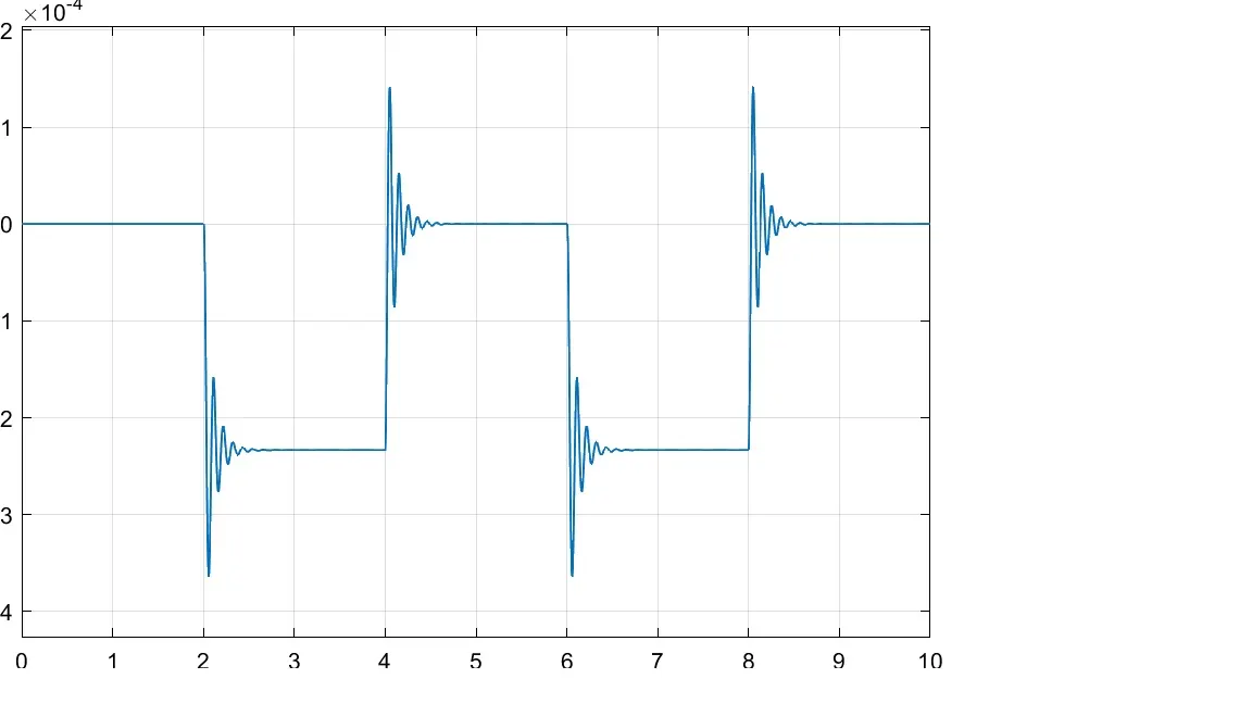
We get a plot as shown below. There is a disturbance initially when the switch is closed and comes to constant.
Model 2: Using thermistor and sensing its temperature under certain conditions.
Model creation:
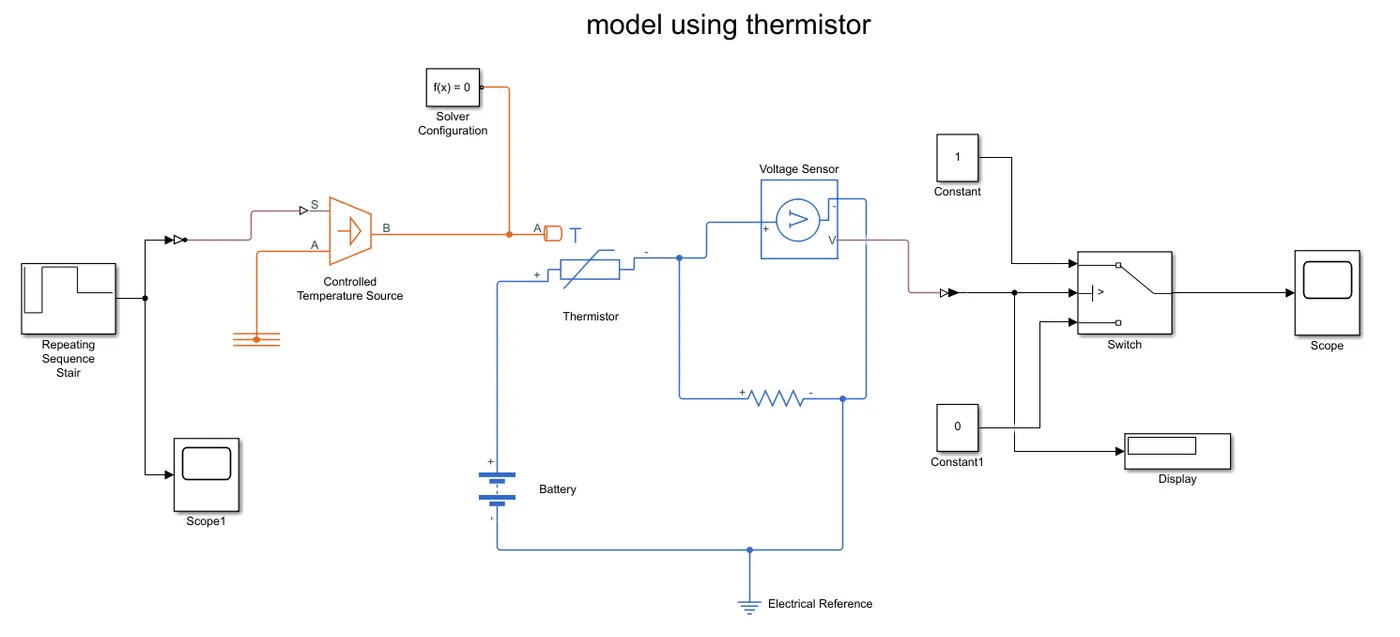
- We give 5 temperature inputs at every 10 seconds i.e., for 50 seconds. We give temperatures in Kelvin. Temperatures are 293, 300, 300, 296, 296 for every 10 seconds.
- Add signal repeating sequence stair block for input temperatures. Give temperatures as above and sample time as 10 seconds. Here sample time means, each value of temperature at a certain time period.
- Give scope for repeating sequence stair block for knowing the input plot of it.
- Add controlled temperature source block for maintaining temperature. Join the stair block to controlled temperature source with the help of Simulink-PS converter. Add at the point 'S'.
- Add temperature reference block and join with the point 'A'.
- Add thermistor block and join the point 'A' with point 'B' of the source block.
- Add battery block for source to pass the current in the circuit.
- Add voltage sensor block and resistor block and join with the thermistor. Add an electric reference block.
- Join all connections as shown in the circuit figure.
- Since we need to operate in ON and OFF conditions, we add a switch block with inputs. Inputs are given as 0 and 1 with two constant blocks.
- Join the point 'V' of voltage sensor to the switch. The switch operates in the values between 0 and 1. It is joined with the help of a converter block.
- We use display block to know the threshold value and joined with the switch. Scope block is used to know the output from the switch.
- Give solver configuration block by joining near thermistor.
- Run the simulation under 50 seconds. We get a value in the display and copy the value of it and paste it in the switch threshold value.
- Now run the model once again for 50 seconds to know the output.
- The output is known in the scope. Scope plots are known by double-clicking on it.
Model:
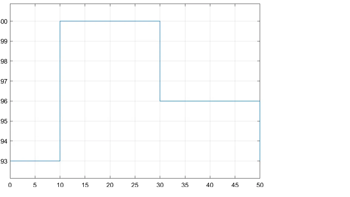
Input scope: We can observe 50 seconds of time in X-axis and temperature on Y-axis. The below plot shows the conditions of a temperature source at different time.
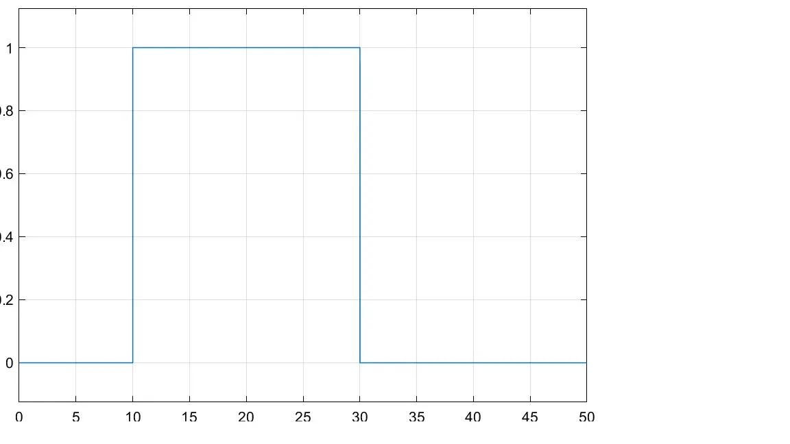
Output scope: We can observe the changes that occurred in voltage under ON and OFF conditions at 50 seconds time period.
Conclusion: Hence, the Simulink model is created of a doorbell using solenoid under certain conditions. Simulink model created using thermistor for sensing temperature under ON and OFF conditions.