Week -2
- DOORBELL USING SOLENOID
AIM:
To make a simulink model of a door bell using a solenoid block.
OBJECTIVE:
Create a situation, where the switch is closed for 2 seconds and then released. Observe the physical movement of the plunger (metal arm).
THEORY:
SOLENOID
A solenoid is a type of electromagnet formed by the helical coil, which produces a magnetic field when an electric current is passed through it. The magnetic field produced is uniform along the axis of the solenoid. Depending upon the length and radius, the solenoids are divided into different types. But in common, the length of the helical coil is more than its diameter. In our doorbell system, solenoid has a ferromagnetic plunger (which acts as a metal core) along with the helical coil which slides(linear motion) when a magnetic field is produced in the coil. So, solenoids basically convert electrical energy to mechanical work. As the plunger moves up and down when the power is supplied, if we place small metallic plates around it, then it produces a soothing sound.
The magnetic field density of a solenoid can be measured as:
B=μNI/l
Where.
B - Magnetic flux density
μ - Magnetic constant
N - Number of turns
I - Current
l - Length
So, magnetic field density depends upon the number of turns, current passing through the coil and the length of the coil.
The basic components required to model the doorbell using solenoid are:
- Battery
- Switch
- Solenoid with plunger
SIMULINK MODEL:
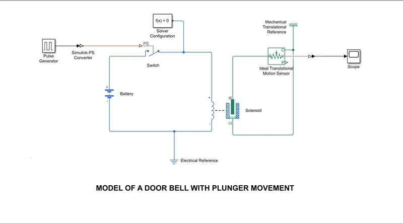
Battery:
The battery block here works as a dc voltage source which gives the power to the solenoid. It is a simscape block and has two terminals. The positive terminal is connected to the positive side of the solenoid with the switch in series. The negative terminal is connected to the negative side. The battery has a nominal voltage as a parameter without any variables and charge is kept at infinite.
Switch
The switch here works on the external physical signal, which closes the circuit. As the physignal value is greater than threshold value, the switch is closed and when the signal is less than the threshold, the switch is open. It has two electrical conserving ports connected to battery and solenoid and one physical signal port PS which is used for the physical signal input.
Pulse generator
This block generates the square wave pulses at regular intervals. The waveform parameters like Amplitude, Pulse width, Period and Phase delay determine the shape of the output waveform. As it is a simulink model, the simulink to PS converter block is used to connect the pulse generator and the switch to provide the pulses to the PS port of the switch.
Based on the objective, the parameters are selected as:
Amplitude = 1; Period = 4 sec; Pulse width = 50%; Phase delay = 2 sec.
Solver configuration
The solver configuration block specifies the solver parameters that our model needs before the simulation. Each simscape block requires exactly one solver block for the simulation. It mainly defines the solver settings for simulation.
Ideal Translational motion sensor
This block measures the velocity or displacement in a mechanical translational network. The two ports R and C are the conservating ports with R acts as a positive probe and C acts as the reference probe respectively. The physical signal ports V (velocity) and P (position) are the output ports. So, R is connected to the node whose motion is monitored and C is connected to the mechanical translational reference which acts as the ground.
To measure the velocity and position the ports V and P are connected to the scope for the output results.
CONCLUSION:

Input waveform
As per the pulse generator, the square waveform is given as input. As seen in the input the amplitude is one and the phase delay is 2 seconds, so the amplitude is zero for the first 2 seconds. As the period is 4 seconds and the pulse width is 50%, the square pulses are produced for every 2 seconds. So, as per the objective the switch is ON for 2 seconds. The switch closes completing the circuit and the battery provides the required power and as the current flows in the helical coil of a solenoid, a uniform magnetic field is generated. Due to the north and south pole of the magnetic field, the plunger (Rod) moves up and down i.e oscillates as per the output results shown below.
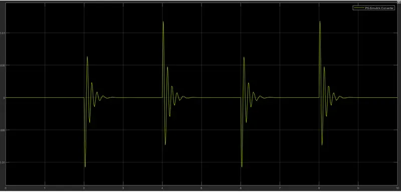
Output waveform
- SENSE TEMPERATURE USING THERMISTOR
AIM :
To sense the temperature of the heater using thermistor and turn on or turn off the fan as per the conditions.
OBJECTIVE :
Temperature source: 20 °c from 0 to 10 seconds
27 °c from 10 to 30 seconds
23 °c from 30 to 50 seconds
Fan conditions: ON if the temperature above 25 °c, off otherwise.
THEORY :
Thermistor:
Ohm’s law agrees with its statement V=IR, when the temperature is constant. But as the temperature changes the resistance value changes which indicates resistance is temperature dependent. So, a thermistor is a type of resistor whose resistance is dependent on the temperature. The word thermistor is a formation of thermal and resistor.
There are two types of thermistors. Negative temperature coefficient (NTC) thermistor has low resistance value at high temperature. As the name indicates, there is a decrease in resistance value with the increase in temperature. Therefore NTC can be mainly used for the temperature sensors.
Positive temperature coefficient (PTC) thermistors have more resistance with increase in temperature. Therefore these are mainly used for self regulating heating elements.
The simscape block of thermistor has electrical conserving terminals of positive and negative which are connected to the positive terminal of the battery and the positive terminal of the resistor. It also has the thermal port A which is connected to the output port of the controlled temperature source.
The basic components required in the model to sense the temperature using thermistor are:
- Thermistor
- Dc voltage source
- Resistor
- Controlled temperature source
- Signal builder
- Voltage sensor/Current sensor
- Switch
SIMULINK MODEL :
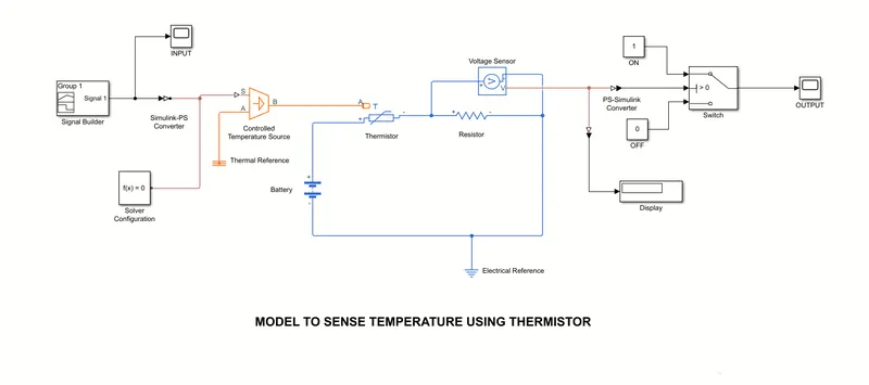
Battery:
The battery block here works as a dc voltage source which makes the current flow through the resistor. It is a simscape block and has two terminals. The positive terminal is connected to the one side of the resistor with the thermistor in series. The negative terminal is connected to the opposite side. The battery has a nominal voltage as a parameter without any variables and charge is kept at infinite.
Resistor:
The resistor acts as the heating element. As the current passes through the resistor, based upon its resistance value, heat is generated. And therefore can be used as a heating element to measure the temperature. Usually the resistance has no terminals but for the convention, positive and negative terminals are associated so that the power in the resistor is always positive, Here the parameter of resistance is 1 ohm.
Controlled temperature source:
This block has two thermal ports A and B. Port A is the input and port B is the output terminal. This block represents an ideal energy source in the thermal network and the temperature difference between the two ports A and B is always controlled irrespective of the heat flow rate. The temperature difference is set by the physical signal port S. It is maintained that the temperature at port B is always greater than port A. Therefore the controlled input signal is given to the physical port S by the simulink to PS converter. The port A is connected to the thermal reference and port B is connected to the thermistor.
Signal builder:
This block can be used to build the required signal based on our required conditions, So, as per the objective of the temperature source, the signal is built with time in the X-axis and temperature in the Y-axis. As the temperature unit of the thermistor is set in Kelvins (K), the conditions of the temperature source need to be converted to kelvins. 273+degree celsius gives the required value in kelvins. so , as per our conditions:
293k from 0 to 10 seconds
300k from 10 to 30 seconds
296k from 30 to 50 seconds
Voltage sensor:
As the resistor is an electrical component, we can only measure the current flowing or the voltage across it. So, by using the current sensor in the series or by using the voltage sensor in parallel, one can sense the amount of voltage or current passing through the resistor. Here we are using the voltage sensor to calculate the fan conditions as when the switch is ON or OFF.
It is an ideal voltage sensor, a device that converts voltage measured between the resistor to the physical signal proportion to the voltage. So this physical signal by using the signal port V is connected to the switch by using the ps to simulink converter block. The positive and negative terminals are the conserving electrical ports connected across the resistor. The physical signal port V is also connected to the scope or display to know the voltage which can be used as a fan ON/OFF condition for the switch.
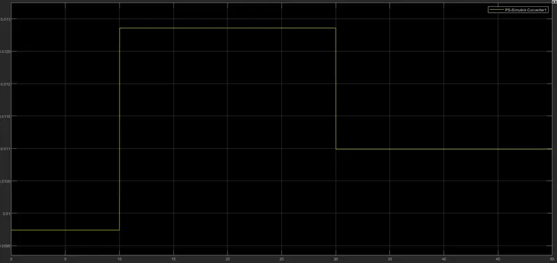
So, at 298k the output value of the voltage sensor can be measured by the block display and the value is about 0.01189.
Switch:
This simulink block has three ports. The signal passes through input 1 when the input 2 threshold condition or criteria is satisfied. If not then the signal passes through the input 3. Here the threshold value is about 0.01189. So, the output of the voltage sensor is connected to the input 2 with the help of ps to simulink converter block.
Solver configuration
The solver configuration block specifies the solver parameters that our model needs before the simulation. Each simscape block requires exactly one solver block for the simulation. It mainly defines the solver settings for simulation.
CONCLUSION :
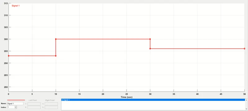
Signal builder waveform
The above waveform is built from the given conditions:
0 to 10 seconds - 293k
10 to 30 seconds - 300k
30 to 50 seconds - 296k
Voltage sensor output waveform
Above graph represents the physical signal of the voltage sensor equivalent to the varying temperature from time to time. So from the above waveform, we can get the threshold value at 25 °c ie., at 298k is about 0.01189. So, this value is given as the threshold condition in the switch.
Output waveform
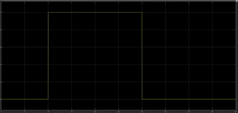
So, from the above graph,
0 to 10 seconds - 293k<298k - Fan is OFF.
10 to 30 seconds - 300k>298k - Fan is ON.
30 to 50 seconds - 296k<298k - Fan is OFF.
Therefore, the results are obtained as per the conditions.