Week -2
Aim :-
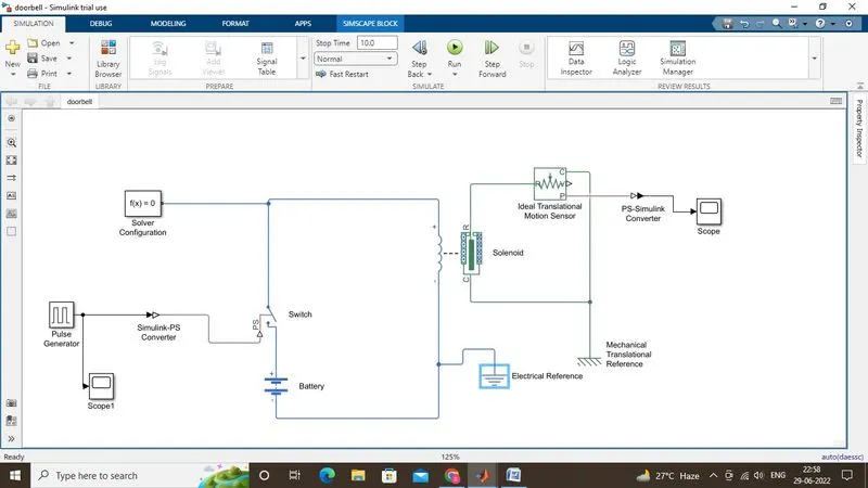
- Make a Simulink model of Doorbell using Solenoid block when the switch closed for 2 seconds and then released.
- Observe the physical movement of the plunger inside the solenoid.
- Use a Thermistor to sense the temperature of a Heater and turn on/off as per the given conditions.
Objective:-
- In the Doorbell model,create a situation when the switch is closed for 2 seconds and then released.
- Also,observe the movement of the solenoid’s plunger.
- Given conditions of the thermistor :-
Temperature Source : 20 deg C from 0 s to10 s ,27 deg C from 10 s to 30 s,23 deg C from 30 s to 50 s .
Fan Conditions : ON if the temperature is above 25 deg C,OFF otherwise.
Body :-
Doorbell Challenge
Simulink Model : https://drive.google.com/file/d/1nvUB2ppWHkPtnh9K0YyMAoJJAoyZBr1w/view?usp=sharing
Results :
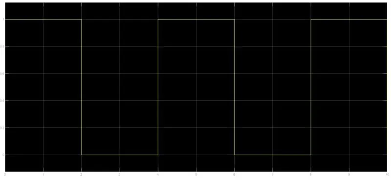
Input pulse :-
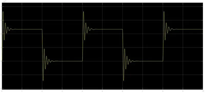
Plunger Movement :-
Workflow :
- Initially,a basic model is built based on the diagram given in the challenge.
- Now,for closing the switch the external physical signal input must be greater than its threshold.
- Using pulse generator block as input to the switch,pulses are generated for every 2 seconds of the total simulation time ie.,10 seconds.
- As the switch closes for every 2 seconds,the solenoid extracts electrical power from the battery in these intervals which causes its plunger
- The movement of the plunger can be observed in the scope block by using the PS-Simulink Converter block.
- Also,the physical signal input is given to the switch by converting the Pulse Generator output to physical signal using Simulink-PS Converter.
- Solver configuration is used to solve the equations associated to the simulation in the backend.
- Ideal Translational Motion Sensor is used to sense the motion of the plunger while the switch is closed.
- A reference frame/point is provided based on the kind of blocks used in order to provide initial conditions to the solver configuration block.
Thermistor Challenge
Simulink Model :https://drive.google.com/file/d/1al4bgVaTzz4LCqaSAttKt_YObRJ_LBIy/view?usp=sharing
Results :
Plot 1:
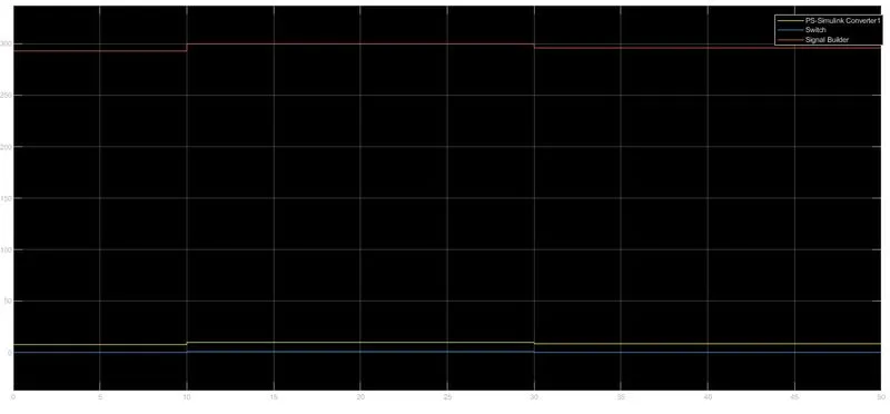
The above plot shows the input signal(Red line) given to the Signal Builder block,Voltage across the resistor(Yellow line) and the switch operations (Blue line).
Plot 2 :
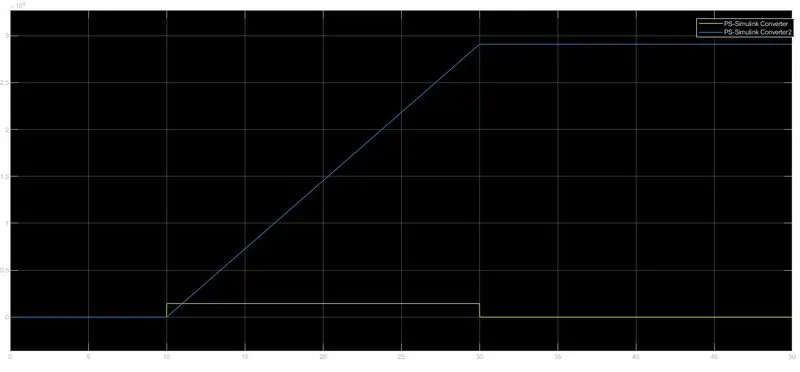
This plot shows the angular movement (angular velocity and angle) of the DC Motor in different conditions .
Workflow :
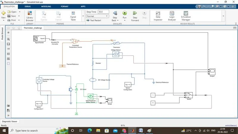
- Given temperature wrt time conditions are given to the signal builder block and this signal is converted to physical signal using Simulink-PS Converter and given to the Controlled Temperature Source(CTS) through port S.
- CTS output signal is further given to the Thermistor using its thermal port A and
- a Resistor along with a DC Voltage Source is connected in the same circuit to drive the Thermistor.
- Now,as per the given conditions when the temperature of the heater > 25 deg C,fan should be ON,OFF otherwise.
- So,in this range of 10-30 sec,our temperature is 27 deg C (300 K) i.e., only in this range our (DC Motor) will rotate.
- Note the corresponding voltage drop across the resistor in this range and set the threshold value of the switch block < this voltage.
- When the input value to the control port 2 of the switch block > threshold of the switch block,input 1 will pass i.e., switch is closed and current will flow in the circuit which will drive our DC motor,else input 3 will pass ie., switch is open.
- The value of the input signal,voltage across the resistor and output of the switch can be seen from the Scope 1.
- Scope shows the output of the IRMS ie., angular velocity and angle by which the motor rotates for the given simulation time.